1
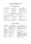
Gerstel Field Service Manual
Cooled Injection System - CIS4
CIS 4 Cooled Injection System
Field Service Manual • 1
Field Service Manual • 2
CIS 4 Cooled Injection System
Contents list
1.
Site Preparation............................................................................. 5
1.1 Gerstel CIS4 System .................................................................. 5
1.2 Instrument Configuration Questionnaire .................................... 5
2. Installation Guide .......................................................................... 6
2.1 CIS 4 Installation Checklist ........................................................ 6
2.1.1 Installation ............................................................................ 6
2.2 CIS4 Installation Guide ............................................................... 8
3. CIS4 Training Guide ....................................................................11
3.1 System overview. .......................................................................11
3.2 System Operation ..................................................................... 12
3.3 Essential points ......................................................................... 13
4. Troubleshooting Guide .............................................................. 15
4.1 Leak tests .................................................................................. 15
4.1.1 Quick leak test: ................................................................... 15
4.1.2 Installation leak test............................................................ 15
4.2 Application issues..................................................................... 16
4.3 Hardware issues ....................................................................... 17
5. Maintenance Guide..................................................................... 18
5.1 Preventative Maintenance Procedure ..................................... 18
5.1.1 Preliminary Observations .................................................. 18
5.1.2 Preparation of System ....................................................... 18
5.1.3 Introduce the column at least 10 mm into the septum ...... 18
5.1.4 Maintenance of Septumless Head (SLH) ......................... 18
5.1.5 Maintenance of CIS 4 ........................................................ 19
5.1.4 Replacement of Adsorption trap........................................ 20
5.1.5 Leak Test ............................................................................ 20
5.1.6 Reconnect capillary column .............................................. 20
CIS 4 Cooled Injection System
Field Service Manual • 3
5.1.7 Check Controller Temperature Calibration ........................ 21
5.1.8 Update the Controller Firmware......................................... 22
5.1.9 Test Run ............................................................................. 22
5.2 Service Controller 505 .............................................................. 23
5.2.1 Prepare Controller for Service ........................................... 23
5.2.2 Exchange Fuse .................................................................. 23
5.2.3 Change Fan ....................................................................... 24
5.2.4 Change CIS 4 voltage from 40V to 44V ............................ 24
5.5.5 Change Firmware .............................................................. 24
5.2.6 Firmware Update Software ................................................ 26
5.2.7 Circuit board installation ..................................................... 27
5.2.8 Change main board ........................................................... 27
5.2.9 General description of main board .................................... 29
6. Appendices .................................................................................. 30
6.1 Part numbers ............................................................................. 30
6.1.1 Main parts........................................................................... 30
6.1.2 Spare parts ......................................................................... 31
6.2 Cable Diagrams ........................................................................ 34
6.3 Drawíngs.................................................................................... 35
6.4 Methods ..................................................................................... 36
6.5 Specifications / Values ............................................................. 37
Field Service Manual • 4
CIS 4 Cooled Injection System
1. Site Preparation
1.1 Gerstel CIS4 System
The following is a list of items necessary for installation of the Gerstel
CIS4 system. Please insure that all the items listed below are available
at the time of installation. Also, please complete the instrument configuration questionnaire below and fax it to the Gerstel service department
at 410-247-5887.
! 1 available power outlet
! Liquid nitrogen (LN2) dewar (22psi)
! 1/8" and 1/16" Swagelok fittings and ferrules
! Necessary bench space – 1-2 feet of bench space for Gerstel controller
! Appropriate environmental conditions – no excessive heat or moisture in area, no corrosive or toxic materials in area
1.2 Instrument Configuration Questionnaire
GC Model:
Peripheral systems (purge and trap, headspace, valves, etc):
Computer and operating system:
Available comm ports:
Detectors (front/rear/other):
Inlets (front/rear):
Auxiliary heaters used (MSD, FPD, etc):
CIS 4 Cooled Injection System
Field Service Manual • 5
2. Installation Guide
2.1 CIS 4 Installation Checklist
2.1.1
Installation
!
Verify of completeness of kit
! Manual
! CIS
! Controller
! Handheld
! Pneumatic (tubing, cable, etc)
! accessories
! Power supply
! Remote-Start-cable
!
Leak test
!
Manual pneumatic 20 kPa / 30 min
!
CIS - 4 EPC 0.05 psi / min
!
Configuration of controller
! fuses
! Boards
! NV parameters
!
Test method chromatogram
!
Familiarization
!
Manual
Field Service Manual • 6
CIS 4 Cooled Injection System
!
Control with handheld
!
Injection modes (split, splitless, solvent vent, etc)
!
Cleaning SLH
!
Liner change
!
Column installation
CIS 4 Cooled Injection System
Field Service Manual • 7
2.2 CIS4 Installation Guide
This is an outline of the sequence of events for a typical CIS4 installation.
It is meant to be a guideline and the actual sequence is up to the individual installer. However, this sequence has been proven to be effective
over the last 4 years and should be followed closely if possible.
Note: If the CIS4 is to be installed on a 5973 system, instruct the customer to vent the instrument prior to the beginning of the install. This is
necessary because the left side panel of the 6890 needs to be removed
to install the CIS. It will also be helpful to turn off the temperature to any
inlets already present in the GC, since they will have to be removed
during the installation.
1. Turn off the GC and remove the necessary panels
-left side,
-hinged top cover,
-small fan cover,
-rear top plastic panel,
-rear top steel panel,
-rear pneumatic module
cover.
Field Service Manual • 8
CIS 4 Cooled Injection System
2. Remove the black plastic inlet
chassis out of the GC, therefore
disconnect the fan and remove
any inlet installed in the GC.
3. Cut out the section of the front inlet
hole that corresponds to the area
where the split line exits a S/SL
port. A Dremel tool can be used for
this or several slits can be made
with a keyhole saw.
4. Remount the black inlet chassis and then re-install any existing GC
inlet in the rear position.
5. Install the CIS4 insulation block and then mount the CIS4.
6. Slip the CIS4 plug through the metal frame adjacent to the inlet chassis
and rout the cable to the back of the GC.
7. Mount the CIS4 pneumatics into the back of the GC
8. Run the 3 steel lines to the side of the instrument and connect the top
2 lines (carrier and septum purge) together using the Swagelok „T“
provided.
CIS 4 Cooled Injection System
Field Service Manual • 9
9. Connect the open port of the Swagelok „T“ to the septumless head
(SLH) of the CIS4. Use a coil around the SLH to provide additional
steel tubing.
Note:
If the customer is present during this process, it may be helpful to
describe what is being done and the fact that it can create a leak in an
MSD system when using the splitless mode. If a Gerstel TDS module
is to be installed, also install the 7mm spacers to raise the inlet at this time.
10. Connect the split line of the pneumatics to the split outlet of the CIS4.
11. Run the cryo tubing. In CIS4-only systems, it is best to route the cryo
tubing in the side panel of the GC (compression of the foam insulation
is necessary).
12. Remount all panels removed in step 1, and reconnect the MSD if
applicable.
Field Service Manual • 10
CIS 4 Cooled Injection System
3. CIS4 Training Guide
3.1 System overview.
For new operators and those that are not familiar with the system this is
a brief overview of the system. It is also a good introduction to the
familiarization process.
Explain that the CIS can do everything that a typical s/sl inlet will do. But
it also can do solvent venting injections, which allow you to inject more
than the standard 1 or 2 µl. Explain the 3 main injection types and their
pneumatic modes.
-
Split injection: Single pneumatic mode. The inlet is in split before,
during and after the injection.
- Splitless injection: Uses 2 pneumatic modes. The inlet is in splitless
mode before and during the injection and then switches to the split
mode after a specified time.
- Solvent venting injection: Uses 3 pneumatic modes. The inlet is in the
split mode before and during the injection. However, the inlet temperature is lowered to a point where the solvent still has vapor pressure,
but the analytes do not. Once the solvent is vented away through the
split vent, the inlet switches to the splitless mode to transfer the
analytes to the column. After about 1 minute, when the analytes are
vaporized and have been transferred to the column, the inlet switches
back to split for the remainder of the run.
Note:
Because of the small volume of the CIS liner (about 1/10th the volume
of a typical s/sl), it is recommended that the inlet be cool for all injections
over 1µl to prevent possible „back-flashing“ of compounds and contamination of the septumless head.
CIS 4 Cooled Injection System
Field Service Manual • 11
3.2 System Operation
a. Use the FID check sample (or appropriate detector check sample) to
develop and save a base method that uses all parts of the system.
(See Test and Evaluation section below). Save the HP and Gerstel
methods as Gerstel.m and Gerstel.mpg respectively. These methods
can be used in the future for diagnostic and re-training purposes. For
the CIS, this method should be solvent venting (although additional
split and splitless methods can be developed as well if there is time).
Here are some guidelines for the method:
Gerstel Method Parameters:
-
CIS
CIS
CIS
CIS
CIS
Initial Temp: Approximately 60° C below BP of solvent used
Initial Time: 0.05 minutes
Ramp Rate: 10° C/second
Final Temp: 350°C
Final Time: 3 minutes
HP Method Parameters:
-
Injection Mode: Solvent Vent (splitless)
Inlet Pressure: Optimum for column
Total Flow: 50 ml/minute
Vent Flow: 50 ml/minute
Vent Pressure: same as inlet pressure
Until: 0.05 minutes (Same as CIS initial time)
Purge flow to split vent: Determined by total flow set above
At: 1 minute
Oven Initial Temp: 60°C
Oven Initial Time: 1 minute
Oven Ramp Rate: 20°C/minute
Oven Final Temp: 260°C
Field Service Manual • 12
CIS 4 Cooled Injection System
- Oven Final Time: 1 minute (total run time 12 minutes)
- Injection Volume: 1-5µl
- Flow Mode: Constant flow
b. Explain what the CIS4 is doing during a run cycle. It helps the customer
to understand the operation of the system if it is visibly performing
during the explanation.
c. Print out a copy of the completed method and a chromatogram
produced using it. Leave one copy at the customer site. Make a copy
of the method and chromatogram to be placed in the customer file at
Gerstel, Inc.
d. Do injections in other modes to illustrate the differences if necessary.
3.3 Essential points
Column length into inlet
The manual contains a diagram showing the 17mm length and how to
set it. Instruct the customer to use the CIS4 to crimp the ferrule to the
column, and then adjust the ferrule to the proper setting.
Graphpack ferrules
Describe the way GP ferrules are made and why they are used (sealing
power of graphite, temperature stability, etc).
Modes of operation
It is a good idea to go through all modes (as described in the overview
section above), but Solvent Venting should be explained thoroughly because it is new to most users. Use the HP Chemstation software to
illustrate how different areas open up as you select different injection
modes. Insure that the customer knows that it is necessary to set a
splitless time to get an actual splitless injection and show how to input a
basic set of solvent venting parameters. Explain that simply selecting a
mode will not necessarily automatically input flows or times for the mode.
CIS 4 Cooled Injection System
Field Service Manual • 13
Setting of parameters in both the Gerstel and HP software
Explain that the Gerstel only controls the temperature of the inlet. The HP
software controls the pneumatic functions because the pneumatic modules are manufactured for us by HP and are an integral part of the GC.
Volume of liner, backflashing
Explain the small volume of the liner and the fact that injections over 1µl
should be done cold to prevent backflashing of sample into the cooler
parts of the inlet. Since Gerstel equipment (or any non-HP equipment),
need to enable the „Auto-Preprun“ function of the GC, an MS detector
will show a large air background if tuned in the splitless mode. This is
because the Auto-Preprun function switches the pneumatic mode of the
inlet to splitless as soon as the GC becomes ready, as opposed to just
prior to injection if it is disabled. This lowers inlet total flow to a point
where a leak is created through the septum purge channel of the pneumatics module. Always tune in the split or solvent venting mode.
Field Service Manual • 14
CIS 4 Cooled Injection System
4. Troubleshooting Guide
4.1Leak tests
4.1.1
Quick leak test:
!
Set inlet mode to „Splitless“ on GC front panel
!
Press twice the PREP button (Prep-LED will light not blinking)
!
Read the total flow (should be Col.flow + Purge ~ 4-6ml/min)
4.1.2
Installation leak test
Action from user
Close the Septum
purge outlet
Potential cause of
Potential cause of
leak if pressure or
leak if total flow
Possible solution
flow return to
does not decrease
normal
Septum purge reg. Exchange EPC
Defective
Disconnect column
and install blind
plug
defective / wrong
Ferrule
Broken column
Unsrew carrier line o-ring in front of
from CIS and close EPC missing
it (septum, thumb) t-piece in left side
GC
Connect carrier line
with SLH, tighten
bottom of SLH with
thumb
SLH plunger
blocked
Carrier connection
is loosen
Change ferrule
Change column
Check o-rings
Tight the swageloke
connection
SLH maintenance
Install SLH on CIS
and disconnect GPAdapter
GP-Adapter loosen Exchange seal or
or defective silver
GP-Adapter
seal
Connect carrier gas
line with split line
Graphpack adapter Tighten or change
leaking
adapter
CIS split line broken Exchange CIS
CIS 4 Cooled Injection System
Field Service Manual • 15
4.2 Application issues
Problem
Air background in MSD
Possible Cause
Inlet in splitless mode
Leak at carrier gas fitting
Leak at SLH o-ring
Poor recovery of analytes
High background in
systemHigh background
(cont.)
Field Service Manual • 16
Leak in system
Possible Solution
Put inlet in either split or
solvent vent mode to tune
Tighten fitting or replace
teflon ferrule
Remove and disassemble
SLH and clean or replace
o-ring
Leak at teflon needle
guide during injection
Wrong syringe
Check all possible leak
points listed above
Check tightness of needle
guide
Use right syringe
Dir ty or contaminated liner
Leak at teflon needle
guide during injection
Contaminated CIS
Bad column
Dir ty detector
Replace CIS4 liner
Check tightness of needle
guide
Clean the CIS
Change Column
Clean Detector
CIS 4 Cooled Injection System
4.3 Hardware issues
Problem
CIS not heating at all or
not reaching proper
temperature
Possible Cause
Cable loose or unplugged
Possible Solution
Check security of cable
Fuse blown in C505
controller
Heating wire of CIS
damaged
Replace fuse
LN2 valve stuck par tially
open
Allow valve to thaw and
retry or check inside of
valve for debris
CIS cannot reach pressure Leak in system
Send unit to Gerstel for
repair / Exchange system
See above
Insufficient flow
programmed into method
Increase total flow rate
No display / no letter
Power cord loosen
Not switched on
CPU fuse blows
Check power cord
Switch on controller
Change both CPU fuses
Temp error 1 (no heating)
CIS unplugged
Heater
Plug system
Exchange system
Temp error 3 (slow
heating)
Wrong configuration
Cryo valve open / blocked
Change fuse CIS 3 / 4
Change cryo valve
Line irq
Wrong configuration
Blown fuse
Change to 50 / 60 Hz
Change both CPU fuses
CIS 4 Cooled Injection System
Field Service Manual • 17
5. Maintenance Guide
5.1 Preventative Maintenance Procedure
5.1.1
Preliminary Observations
☞ Discuss any problems the customer is having or has observed
with the instrument.
5.1.2
Preparation of System
☞ Cool down the system. Oven and inlet temperature shall reach
nearly room temperature before continuing.
☞ Turn off all heaters and cooling devices. (e.g. Oven Off, Cryo
Cooling Off, Aux Temp (MSD) Off, Inlet Temp Off).
☞ Shut off CIS inlet pressure.
☞ Disconnect the column from the inlet and seal the open end of
the capillary with a septum.
5.1.3
Introduce the column at least 10 mm into the septum
☞ In case of using a MSD control its vacuum. If the pressure
raises rapidly vent the system.
☞ Unscrew the carrier gas line from the inlet and remove the
Teflon carrier gas connection ferrule.
☞ For safety close all coolant reservoir valves.
5.1.4
Maintenance of Septumless Head (SLH)
☞ Unscrew the SLH from CIS and place it on a clean tissue.
☞ Take off the SLH cap and remove the needle guide.
☞ Unscrew the sealing nut from the sampling head and carefully
remove the O-ring and compression spring.
Field Service Manual • 18
CIS 4 Cooled Injection System
☞ Carefully insert a microliter syringe with 0,64 mm (23 gauge)
external diameter into the head so that valve plunger and
O-ring move slightly out of the head.
☞ Clean SLH carefully with a non-polar solvent (e.g. Benzine,
Hexane) and remove any deposits with a soft brush; do not use
a sharp object for cleaning.
Safety Warning Organic Solvents:
Do not use just any solvent available in a laboratory. Consider
that solvents like e.g. Acetone or Ethylacetate can already
dissolve the paint. Be aware that Benzine is a pure fractionated
gasoline, do not mix up with Benzene (German: Benzol) which
is highly carcinogenic. Avoid any solvent, especially if the
service technician does not know the composition. Solvents
which are hazardous to your health (skin, eyes, respiration, etc.)
or solvents which are highly flammable or even explosive have
to be rejected and shall not be used under any circumstances.
☞ Exchange plunger, spring and O-rings.
☞ Reassemble the SLH. Ensure that the area is totally lint-free
and that the O-rings and compression spring are not damaged. Keep the SLH in a clean environment while maintaining
the CIS.
5.1.5
Maintenance of CIS 4
☞ Take out liner
☞ Unscrew the GRAPHPACK adapter and remove the seal..
☞ Clean CIS carefully with a non-polar solvent (e.g. Benzine,
Hexane) and remove any deposits with a soft brush; do not use
a sharp object for cleaning.
☞ Prepare a new liner with GRAPHPACK ferrule.
CIS 4 Cooled Injection System
Field Service Manual • 19
☞ Screw a new GRAPHPACK adapter with new seal at the
bottom of the CIS.
☞ Build in the new liner.
☞ Screw on sampling head.
☞ Reconnect carrier gas line using a new Teflon ferrule.
5.1.4
Replacement of Adsorption trap
☞ Disconnect the old adsorption trap.
☞ Connect the new adsorption trap (The end marked with „P“
shows to CIS).
5.1.5
Leak Test
☞ Cap GRAPHPACKadapter with an appropriate sealing ferrule.
☞ Set inlet pressure to 25 psi and total flow to 60 ml/min using split
mode.
☞ Press „Prep Run“ on Agilent GC keypad to execute.
☞ Wait until the pressure is equilibrated. (e.g. 30 seconds for the
pressure to stabilize).
No deviation shall be indicated in the status dialog box (exception: Oven not ready; Waiting for host system; External device).
☞ Cap septum purge vent with Swagelok 1/8" plug and set inlet
pressure off immediately.
➢
Pressure drop shall be less 0.05 psi/min, during
a period of 10 min
( => max. pressure drop: 0.5 psi/10min).
☞ If pressure drop is higher than expected search for leaks.
Eliminate all leaks and repeat leak test until the pressure drop
is admissible.
5.1.6
Reconnect capillary column
☞ Remove all blanking plugs.
☞ Cut the column below septum.
Field Service Manual • 20
CIS 4 Cooled Injection System
☞ Push a new GRAPHPACK-2M ferrule with the metal side over
the capillary column.
☞ Cut the column again to leave a clean end with no graphite
residue.
☞ Fix the ferrule at a distance of 17 mm from the end of the
column.
☞ Reinsert column into CIS inlet.
☞ Reconnect all coolant supplies.
5.1.7
☞
☞
☞
☞
☞
☞
☞
☞
☞
☞
Check Controller Temperature Calibration
Assure that the controller is powered off.
Unplug CIS cable.
Plug the calibration adapter in the CIS port of the controller.
Turn controller power on.
When the controller starts heating or cooling press „On/Off“ to
stop tempering.
Make sure that the calibration adapter switch is in position 1.
Temperature reading at the handheld remote of controller
should be 0°C±1.
Switch to position 3 and take the second reading. Temperature
reading at the handheld remote of controller should be 350°C±1.
If the temperature readings differ significant from the default
settings ask customer if this setting can be recalibrated.
If customer agrees:
- Turn controller power off
- Disconnect customer handheld remote
- Connect the service handheld remote
- Turn controller power on
- Press second service button
- Follow indicated instructions
CIS 4 Cooled Injection System
Field Service Manual • 21
5.1.8
Update the Controller Firmware
☞ If necessary upgrade controller with the latest firmware version. Discuss any firmware upgrade first with the customer. If
he is under obligation to perform an OQ/PV test after every
software upgrade, the customer may not wish to upgrade the
firmware at this point of time.
5.1.9
Test Run
☞ A qualitative chemical test sample is run after installation to
verify proper performance. A single injection is made of the
inlet/detector specific Evaluation Sample. The test conditions
for the configurations listed above are found in the Installation
and Operation manual set that is shipped with the instrument.
Attach the chromatograms generated by this run to the attachment section at the end of this document.
Typical chromatograms are used to evaluate the installation
result. Small differences in the quality of gasses and column
condition can result in the installation chromatogram deviating
slightly from the examples given in the manual.
Field Service Manual • 22
CIS 4 Cooled Injection System
5.2 Service Controller 505
5.2.1
Prepare Controller for Service
1. switch off power
2. remove power cord
3. open controller (2 screws on each side)
5.2.2
Exchange Fuse
1. prepare controller for service
2. push, turn ccw, pull fuse out
3. exchange fuse
Note:
Always change both
CPU-fuses even if only
one is blown. Use
3.15 A fuse for the CPU,
even when 1.6 A is written on board.
Use for CIS4 4AT(slow),
for CIS 3 6.3AT(slow)
CIS 4 Cooled Injection System
Field Service Manual • 23
5.2.3
Change Fan
1. Prepare Controller for Service
2. Remove plug
3. Unscrew fan with 2
screws
4. Change fan, check
the orientation
(fan blowing out of
controller)
5.2.4
Change CIS 4 voltage from 40V to 44V
1. Prepare for service
2. Unsolder cable from pos. 4 on power supply
3. Solder cable to pos. 3 on power supply
5.5.5
Change Firmware
1. Prepare for service
2. Controller
Field Service Manual • 24
CIS 4 Cooled Injection System
3. SN < 7403 0200
a. Exchange old Eprom versus new Eprom (use right tool)
or
b. Change main board with Flash-eprom (SN from Controller
required)
4. SN 7403 0200 – 7403 0499
a. Upgrade the Eprom to a Flash-eprom (SN from Controller
required) (not guaranteed) or
b. Change main board with Flash-eprom (SN from Controller
required)
5. SN > 7403 0500
a. Use the FW-update program
CIS 4 Cooled Injection System
Field Service Manual • 25
5.2.6
Firmware Update Software
1.
2.
3.
4.
5.
Close Master-Software
Go to C:\Gerstel\Firmware and open Update.exe
Choose the correct com port for the controller
Choose the appropriate Firmware, use the pull down menu
Press the „Update“ button
a. Program will first read and erase the old firmware
b. Program then installs the new firmware (visible in „Upload
Information“ window).
6. After successful update close Firmware update SW and
restart Master
7. If update fails,
a. try again or
b. a main board change is necessary
Field Service Manual • 26
CIS 4 Cooled Injection System
5.2.7
Circuit board installation
1. Prepare for service
2. Remove the necessary slot cover from back panel
3. Install board
a. Insure the 24V plug connects to the main board properly
– connecting to pins 1-2, 3-4 or 5-6 (NOT 2-3, 4-5)
b. Affix transistor with insulation to front panel
4. Configure controller to reflect new board with service remote
control
5.2.8
Change main board
1. Prepare for service
2. Remove fan
3. Remove all circuit boards (TDS, MCS, CTS etc.)
4. Remove 4 screws on the
back of controller
5. Unplug the backboard
CIS 4 Cooled Injection System
Field Service Manual • 27
6. Unplug power supply
7. Unscrew main board
with 10 screws
8. Slide the board carefully to the right side ( be mindful of 2 LEDs !!!)
9. Install new board in reverse order
Field Service Manual • 28
CIS 4 Cooled Injection System
5.2.9
General description of main board
Power supply
connector
Fuse
Elkos
for 5V
24V power
connector
Control
LED for
d i f fe r e n t
voltages
E p r o m
with FWg
Eeprom
Te m p .
control
circuit
Board-slots
CIS 4 Cooled Injection System
Field Service Manual • 29
6. Appendices
6.1 Part numbers
6.1.1
Main parts
Controller C505
GC 05845-01
Handheld
GC 08458-40
Firmware f. C505 (Eprom&Floppy)
GC 06720-01
C 505 with Handheld CIS 3
GC 06720-04
C 505 with Handheld CIS 4
GC 06720-52
Upgrade C504 auf C505
CIS 3
GC 03089-64
SLH
ES 09792-99
Exchange CIS 3
GC 06724-00
Injection chamber CIS 3
GC 06671-90
External pneumatic
GC 03632-50
Internal pneumatic GC 5890
CIS 4
GC 07513-64
SLH
GC 08260-00
Pneumatic 6890
ES 11510-00
Exchange injector N2
ES 11511-00
Exchange injector CO2
ES 11512-00
Exchange injector peltier
GC 11264-50
Peltier cooling
GC 11419-00
Pneumatic tubing
GC 07517-90
Injector port bracket black
Field Service Manual • 30
CIS 4 Cooled Injection System
6.1.2
Spare parts
Controller
Ident no
Order no.
GC 08179-00
GC 08746-00
GC 06941-00
GC 09990-33
6620203210
GC
GC
GC
GC
09990-32
09990-31
09990-34
09990-30
GC
GC
GC
GC
GC
GC
05845-01
06915-00
06747-00
09920-00
05017-XX
05823-00
6620210048
CIS 4 Cooled Injection System
Description
Backboard f. 7403xxxx-7405xxxx
Backboard w. 2.ready
E eprom
Fan
Fuse 0,4A
Fuse 0,8A
Fuse 1,6A
Fuse 3,15A
Fuse 4,0A
Fuse 6,3A
Fuse holder
Handheld
Master CIS
Master MCS
Master MPS
RS-232
Spiral cable
Field Service Manual • 31
CIS 3/4
Ident no
Order no.
GC 02426-10
GC 02930-10
GC 05772-00
GC 07393-03
GC 04911-50
6902000020
6902001009
GC 02931-10
GC 05773-00
GC 03138-00
GC 03258-00
GC 08577-00
GC 03089-64
GC 07541-10
GC 07001-10
GC 05772-90
GC 07393-04
GC 07539-10
Field Service Manual • 32
Description
3D-Ferrule (2mm)
Baffled liner
CO2-cooling
DI 1/16"
Fan
Foil, isolator
Heat conductivity grease
Liner with sil. Glass wool
N2-cooling
Peltier element
Protective sleeve
Septum head w. purge
SLH
3D-Ferrule (3mm)
Baffled liner
CO2-cooling
DI 1/16"
Liner with sil. Glass wool
CIS 3
CIS 3
CIS 3
CIS 3
CIS 3
CIS 3
CIS 3
CIS 3
CIS 3
CIS 3
CIS 3
CIS 3
CIS 3
CIS 4
CIS 4
CIS 4
CIS 4
CIS 4
CIS 4 Cooled Injection System
CIS 3/4
Ident no
Order no.
GC 05773-90
GC 03258-00
GC 08584-00
GC 07513-64
GC 09248-00
GC 09128-00
GC 10961-00
GC 07522-00
GC 07244-00
GC 05243-01
GC 07259-45
GC 01117-05
GC 09999-76
GC 09999-10
GC 03091-64
GC 01576-10
GC 06124-20
GC 06124-04
CIS 4 Cooled Injection System
Description
N2-cooling
Protective sleeve
Septum head w. purge
SLH
Oven insulation
Peltier jacket
Protective sleeve
2/2-solenoid valve
3/2-solenoid valve
Charcoal-Filter
GP-Adapter
Knurled nut
Quick acting valve
SLH-Ser vice kit
Teflon guide
Teflon cone
Cr yo tube CIS3, TDS, CTS
Cr yo tube CIS 4
CIS 4
CIS 4
CIS 4
CIS 4
CIS 4+
CIS 4+
CIS 4+
Field Service Manual • 33
6.2 Cable Diagrams
Field Service Manual • 34
CIS 4 Cooled Injection System
6.3 Drawíngs
CIS 4 Cooled Injection System
Field Service Manual • 35
6.4 Methods
Check out:
CIS:
Liner:
baffled
Initial temp: 60°C
Initial time:
0 min
1. rate:
12°C/sec
2. rate:
0°C/min
1. temp:
350°C
2. temp:
0°C
1. time:
3-5 min
2. time:
0 min
Cryo:
On (if present)
GC: s. GC-detector
Field Service Manual • 36
CIS 4 Cooled Injection System
6.5 Specifications / Values
Leak rate:
Manual pneumatic:
20 kpa / 30 min
EPC 6890 / 6850:
0,03 psi / min
Liner volume:
CIS 3:
93mm*1,4mm = 140µl
CIS 4:
71mm*2,0mm = 220µl
Min. temp.:
-150°C (N2)
-70°C (CO2)
30°C (Peltier at 70°C GC oven)
Initial temp.
for CIS 3: -150°C to 150°C
for CIS 4: -150°C to 400°C
Heating rate:
0,5 - 12°C/sec
Finial temp.:
-150°C – 450°C
Heating wire:
CIS 3: 4,8 Ohm
CIS 4: 9,6 Ohm
Pt 100:
110 Ohm (at 20°C)
CIS 4 Cooled Injection System
Field Service Manual • 37
Notes
Field Service Manual • 38
CIS 4 Cooled Injection System
Notes
CIS 4 Cooled Injection System
Field Service Manual • 39
Field Service Manual • 40
CIS 4 Cooled Injection System