1
Supply Cable). The supply
cable is shipped inside the
station with a small portion fed
through the cable connector
mounted on the wall of the
fiberglass shroud. The supply
cable, a six conductor tray
cable, meets NEC
requirements for direct burial
as long as a minimum of 24"
burial depth is maintained.
Those portions of the cable
which have less than 24" of
cover must be contained in
suitable conduit. This includes
the vertical portion dropping to
a 24" depth at the station and
the length rising out of the
ground at the control panel.
NOTE: Wiring must be
installed per national and local
codes. Conduit must enter
panel from bottom and be
sealed per NEC section 300.5
& 300.7.
8a. Procedure for installing
E/One supply cable:
1) Open the lid of the station,
locate the cable and the feed-
thru connector on the wall of
the shroud. If the station has a
field joint and was delivered in
two pieces be sure the 2 halves
of the EQD are securely
assembled together. Loosen
the nut on the connector and
pull the supply cable out
through the connector until it
hits the crimped on stop feature
on the cable, approximately 24"
from the EQD. **IMPORTANT:
All but 24" of the cable must be
pulled out of the station, and the
portion of the cable between the
EQD and the molded in cable
breather should be secured in
the hook provided to ensure
that the pump functions
properly. Do not leave the
excess cable in the station.
2) Retighten the nut. This
connection must be tight or
ground water will enter the
station.
3) Feed the wire through the
length of conduit (contractor
provided) which will protect it
until it is below the 24" burial
depth.
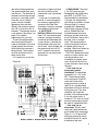
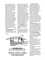
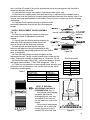
Figure 4
Supply Cable Voltage Drop:
120 VAC Pump = .195 Volts per Foot of Cable
240 VAC Pump = .098 Volts per Foot of Cable
(Maximum Recommended Length = 100 Feet)
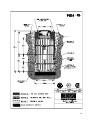
TYPICAL SUPPLY CABLE
CONFIGURATION
4) Position the conduit
vertically below the cable
connector along side of the
station reaching down into the
burial depth. Attach the small
fiberglass guard (Protective
Shroud) provided with the
station to protect the exposed
cable where it enters the
station. Four self-tapping
screws are provided.
5) Run the cable underground, in a trench or tunnel, to
the location of the E/One panel.
Leave a 6-12 inch loop of cable
at each end to allow for shifting
and settling. Connections made
at the panel are shown in the
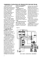
panel wiring diagram (Fig. 2a
and 2b).
9. DEBRIS REMOVAL: Prior
to start-up test procedure, the
core must be removed and the
incoming sewer line flushed to
force all miscellaneous debris
into the tank. Next, all liquid and
debris must be removed. Once
tank is clean, reinstall the pump
and proceed with the test.
10. TEST PROCEDURE:
When the system is complete
and ready for use, the following
steps should be taken to verify
proper installation and
operation:
a) Make sure that the
discharge shutoff valve is fully
open. This valve must not be
closed when the pump is
operating. In some installations
there may be a valve, or valves,
at the street main that must
also be open.
b) Turn ON the alarm power
circuit breaker.
c) Fill tank with water until the
alarm turns ON. Shut off water.
d) Turn ON pump power
circuit breaker. Pump should
immediately turn on. Within one
minute the alarm will turn off.
Within three minutes the pump
will turn off.
7