1
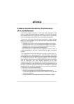
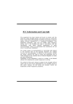
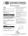
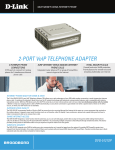
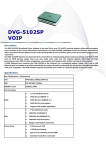
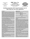
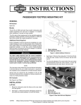
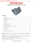
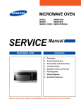
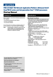
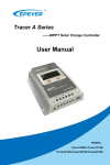
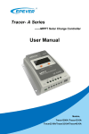
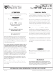
-J04006
REV. 2008-09-23
SPORTSTER FORWARD CONTROL KITS
For XL1200L Models: Discard footrest.
GENERAL
Kit Numbers
is03193
33398-06A, 33395-06A, 33397-07A
Models
2
1
For model fitment information, see the P&A Retail Catalog or
the Parts and Accessories section of www.harley-davidson.com
(English only).
Additional Parts Required
XL1200L models require the purchase of footpegs (part numbers 33134-07CAZ and 33135-07CAZ).
3
4
The rider's safety depends upon the correct installation
of this kit. Use the appropriate service manual procedures.
If the procedure is not within your capabilities or you do
not have the correct tools, have a Harley-Davidson dealer
perform the installation. Improper installation of this kit
could result in death or serious injury. (00333a)
1.
2.
3.
4.
Figure 1. Remove Shift Lever and Footrest
NOTE
This instruction sheet references service manual information.
A service manual for your model motorcycle is required for this
installation and is available from a Harley-Davidson Dealer.
Shift lever
Retaining screw
Footrest bracket
Socket head screw (2)
is03194
2
Kit Contents
See Figure 6, Figure 7 and Table 1.
REMOVAL
5
Remove Stock Shift Lever and Footrest Assembly
1.
See Figure 1. Loosen the shift lever retaining screw (2)
securing the shift lever (1) to the shifter shaft. Slide the
shift lever off the splined shaft. Remove shifter peg from
lever and save for installation. Discard shift lever.
2.
Remove the two socket head screws (4) securing the
footrest bracket (3) to the frame and remove footrest.
Discard screws.
3.
See Figure 7. Firmly press hole plugs (1) into frame screw
holes remaining from footrest removal.
4.
See Figure 2 and Figure 3. Remove the retaining ring (1)
from the clevis to free the footrest clevis pin (4). Remove
the clevis pin and footrest (3) from the footrest support.
Discard retaining ring, clevis pin, spring washer and
footrest bracket.
3
1
1.
2.
3.
4.
5.
4
Retaining ring
Spring washer
Footrest
Clevis pin
Footrest bracket
Figure 2. Remove Left Footrest - All Models except XL883L
and XL1200N
For All Models Except XL1200L: Save footrest for
installation.
For XL883L and 1200N Models: Remove and discard
wear peg (6).
-J04006
1 of 5
is05731
is05732
3
6
1
5
4
1
4
2
2
3
3
1.
2.
3.
4.
5.
6.
Retaining ring
Spring washer
Footrest
Clevis pin
Footrest bracket
Wear peg
Figure 3. Remove Left Footrest - XL883L and XL1200N
Models
Remove Stock Brake Pedal and Footrest Assembly
1.
1.
2.
3.
4.
5.
5
Retaining ring
Clevis pin
Footrest
Brake rod
Screw (2)
Figure 4. Remove Footrest Support Pedal and Brake Pedal
INSTALLATION
Install Forward Control Brake Pedal and Footrest
Assemblies
1.
See Figure 6 and Figure 7. At the lower front of the right
frame downtube, remove the two screws securing the Jclip (B) to the frame. Discard the screws but save J-clip
for installation.
For All Models Except XL1200L: Save footrest for
installation.
2.
Install the other end of the brake rod into the brake pedal
assembly (8). Tighten to 84-144 in-lbs (9.5-16.3 Nm).
For XL883L and XL1200N Models: Remove and discard
wear peg (6).
NOTE
Assemble the brake pedal and footpeg clevis onto the footrest
support bracket (as described in the next step) prior to mounting
the support bracket to the frame. This will allow easier installation of the footrest mount clevis retaining ring (installed to
grooved end of footrest mount clevis).
See Figure 4. At the right footrest, remove the retaining
ring (1) clevis pin (2), footrest (3) and spring washer. Discard all hardware.
For XL1200L Models: Discard footrest.
2.
Remove the exhaust to access the brake rod (4). Follow
the instructions in the service manual.
3.
Remove brake rod (4) from brake pedal and master cylinder bell crank. Discard brake rod.
4.
5.
3.
Remove the two screws (5) and right footrest/brake pedal
support bracket with attached brake assembly from frame.
Discard footrest support bracket and entire brake pedal
assembly.
Slide the brake pedal (8) onto footrest mount clevis (11)
then slide clevis into footrest/brake pedal support bracket
(9). Align hole in the clevis with hole in the support bracket
and install screw (6). Tighten the screw to 18-22 ft-lbs
(24.4-29.9 Nm).
4.
See Figure 6 and Figure 7. Install hole plugs (1) in holes
left from support bracket removal.
Install the footrest mount clevis retaining ring (18) to the
groove at the end of the footpeg clevis.
5.
Position the J-clip (from Step 1) against the frame aligning
the mounting holes. Mount the footrest/brake pedal support
bracket (9) and J-clip to frame using the new screws (3).
Tighten the bracket to 45-50 ft-lbs (61.1- 67.9 Nm).
6.
Obtain the brake rod (15) from kit and thread one end into
the master cylinder bell crank. Tighten to 120-180 in-lbs
(13.6-20.3 Nm).
Footrests must fold up and toward rear of motorcycle if
struck. Failure to set footrests to fold up and back could
result in death or serious injury. (00366a)
7.
-J04006
For All Models: Install footpeg on clevis with spring
washer (2). Make sure spring washer is positioned inside
clevis (11) with the square edge toward the inside. Align
holes and push clevis pin (7) from top down through hole
2 of 5
in clevis. Secure clevis pin using the new retaining ring
(17). Footpegs must be installed so they fold up and back.
For XL1200L Models: Install new footpegs and install
wear peg (19).
For XL1200L Models: Install new footpegs and install
wear peg (19).
For XL883L and XL1200N Models: Install wear peg (19).
For XL883L and XL1200N Models: Install wear peg (19).
Adjusting Shift Lever
Install Forward Control Shift Lever Assembly
If the gears do not engage fully or the toe shifter travel is
incorrect, the shift linkage must be adjusted. See Figure 5.
Adjust the shift rod until the shift pedal is at 45 degrees as
described.
1.
1.
See Figure 5. Remove screw (1) securing the ball joint (2)
to shift pedal (5).
2.
Turn ball joint or shift rod (4) to adjust rod length. Temporarily attach ball joint to shift pedal and check pedal angle.
Make sure an equal number of threads are visible on both
ends of shift rod.
3.
When pedal angle is at 45 degrees, install screw (1).
Tighten to 120-180 in-lbs (13.6-20.3 Nm).
4.
Holding shift rod (4) so that it does not turn, tighten locknuts (3) on each end securely.
8.
Install exhaust following the instructions in the service
manual.
See Figure 6. Obtain shift link arm (13) and screw (6) from
kit. Orient shift link arm pointing straight down and slide
onto shift shaft (exiting engine side cover). Install screw
(6) and tighten to 96-156 in-lbs (11-18 Nm).
2.
Mount footrest/shift pedal support bracket (10) to frame
using screws (3). Tighten to 45-50 ft-lbs (61.1-67.9 Nm).
3.
Slide shift pedal (14) onto clevis (12). Mount clevis on
footrest/shift pedal support bracket (10). Align hole in clevis
with hole in support bracket and secure using screw (6).
Tighten screw to 18-22 ft-lbs (24.4-29.9 Nm).
4.
Install retaining ring (18) to the relief at the end of the clevis
(12) to further secure it in place.
5.
Install screw (4) in far end of the shift rod (16) and into
shifter arm (13).Tighten to 120-180 in-lbs (13.6-20.3 Nm).
6.
Install screw (5) in opposite end of shift rod (16) into shift
lever (14). Tighten to 120-180 in-lbs (13.6-20.3 Nm).
7.
Install shifter peg into new shift lever. Tighten securely.
is03196
5
4
2
1
Footrests must fold up and toward rear of motorcycle if
struck. Failure to set footrests to fold up and back could
result in death or serious injury. (00366a)
8.
Install footpeg on clevis (12) with spring washer (2). Make
sure spring washer is positioned inside clevis with the
square edge toward the inside. Align holes and push clevis
pin (7) from top down through hole in clevis. Secure clevis
pin using the new retaining ring (17). Footpegs must be
installed so they fold up and back.
3
1.
2.
3.
4.
5.
Screw (2)
Ball joint (2)
Lock nut (2)
Shift rod
Shift pedal
Figure 5. Adjusting Shift Pedal
-J04006
3 of 5
SERVICE PARTS
is05468
A
13
A
7
6
4
19
5
C
16
12
2
6
17
18
14
10
3
Figure 6. Service Parts: Forward Control, Left (Shift) Side
is05469
15
18
6
1
11
B
17
9
C
3
19
8
7
2
A
Figure 7. Service Parts: Forward Control, Right (Brake) Side
Table 1. Service Parts Table
Item
Description (Quantity)
Part Number
1
Plug, hole (4)
740
2
Washer, footpeg spring (2)
50912-72
3
Screw, 3/8-16 x 1-1/4 inch (4)
4748
4
Screw, 5/16-18 x 7/8 inch
4359
5
Screw, hex button (lock) 5/16-18 x 1 inch
4016
6
Screw, hex socket 5/16-18 x 1-1/4 inch (3)
3210A
7
Pin, footpeg clevis (2)
45041-01A
8
Assembly, brake pedal, chrome
42702-04
Assembly, brake pedal, polished
42685-04
Assembly, brake pedal, black
42649-07
-J04006
4 of 5
Table 1. Service Parts Table
Item
9
Description (Quantity)
Part Number
Bracket, right rider footpeg support, chrome
42707-04
Bracket, right rider footpeg support, black
42652-04
Bracket, left rider footpeg support, chrome
42706-04
Bracket, left rider footpeg support, black
42651-04
Clevis footpeg right, chrome
42566-04
Clevis footpeg right, black
42504-07
Clevis footpeg left, chrome
42541-04
Clevis footpeg left, black
42503-07
Lever, shift shaft arm, chrome
34670-06
Lever, shift shaft arm, black
34614-07
Assembly, shift lever, chrome
34650-04
Assembly, shift lever, polished
34572-04
Assembly, shift lever, black
34636-07
Assembly, brake rod
34581-04
Assembly, brake rod, black
42645-07
Assembly, shift rod link
34573-04
Assembly, shift rod link, black
34577-07
17
Ring, footpeg clevis pin retaining (2)
11304
18
Ring, footrest mount clevis retaining (2)
11390
19
Wear peg (2) (for XL883L and XL1200L Models only)
33188-08
10
11
12
13
14
15
16
Items mentioned in text, but not included in kit:
A
Stock footrest
B
Stock J-clip
C
Stock footrest (XL883L Models only, separate purchase for XL1200L Models)
-J04006
5 of 5