1
Agilent 4288A 1KHZ/1MHZ CAPACITANCE METER Service Manual
Manual Change
Agilent Part No. N/A
Apr 2009
Change 1
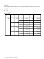
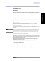
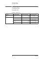
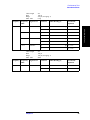
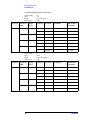
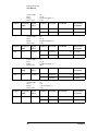
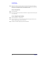
Change the Measurement Uncertainty value of Frequency Accuracy Test (Page 48) to the following.
Cable length: 2m
Frequency
Frequency Shift
Test Limit
Test Result
Measurement
Uncertainty
1 kHz
0%
±0.20 Hz
Hz
± 0.009 Hz
1 MHz
0%
±200 Hz
Hz
± 5.0 Hz
−1 %
±198 Hz
Hz
± 7.2 Hz
+1 %
±202 Hz
Hz
± 6.3 Hz
+2 %
±204 Hz
Hz
± 7.4 Hz
C Copyright 2009 Agilent Technologies
○
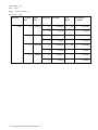
Change 2
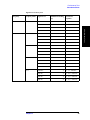
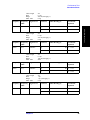
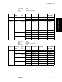
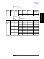
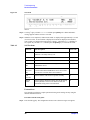
Change the Measurement Uncertainty value of Signal Level Accuracy Test (Page 49) to the following.
Cable length: 2m
Frequency
1 kHz
1 MHz
Frequency Shift
0%
0%
−1 %
+1 %
+2 %
Signal Level
Test Limit
Test Result
Measurement
Uncertainty
1000 mV
±50 mV
mV
± 0.189 mV
500 mV
±25 mV
mV
± 0.103 mV
300 mV
±15 mV
mV
± 0.069 mV
100 mV
±5.0 mV
mV
± 0.038 mV
1000 mV
±50 mV
mV
± 12 mV
500 mV
±25 mV
mV
± 6 mV
300 mV
±15 mV
mV
± 3.6 mV
100 mV
±5.0 mV
mV
± 1.2 mV
1000 mV
±50 mV
mV
± 12 mV
500 mV
±25 mV
mV
± 5.9 mV
300 mV
±15 mV
mV
± 3.6 mV
100 mV
±5.0 mV
mV
± 1.2 mV
1000 mV
±50 mV
mV
± 12 mV
500 mV
±25 mV
mV
± 5.9 mV
300 mV
±15 mV
mV
± 3.6 mV
100 mV
±5.0 mV
mV
± 1.2 mV
1000 mV
±50 mV
mV
± 12 mV
500 mV
±25 mV
mV
± 5.9 mV
300 mV
±15 mV
mV
± 3.6 mV
100 mV
±5.0 mV
mV
± 1.2 mV
C Copyright 2009 Agilent Technologies
○
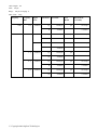
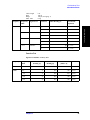
Change 3
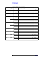
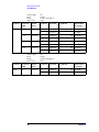
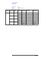
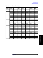
Change the Measurement Uncertainty value of Capacitance Measurement Accuracy Test (Page 50-56) to
the following.
Cable Length: 2m
DUT: 1 pF
Range: 1 pF (Averaging: 1)
Meas. Time:
Long
Frequency
1 MHz
Frequency
Shift
0%
−1 %
+1 %
+2 %
Signal
Level
1000 mV
1000 mV
1000 mV
1000 mV
C Copyright 2009 Agilent Technologies
○
Parameter
Test Limit
Cp
±0.00085 pF
D
±0.00065
Cp
±0.00085 pF
D
±0.00065
Cp
±0.00085 pF
D
±0.00065
Cp
±0.00085 pF
D
±0.00065
Test
Result
Measurement
Uncertainty
pF
± 0.00026 pF
± 0.00005
pF
± 0.00026 pF
± 0.00005
pF
± 0.00026 pF
± 0.00005
pF
± 0.00026 pF
± 0.00005
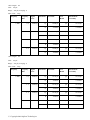
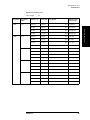
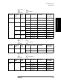
Cable Length: 2m
DUT: 10 pF
Range: 10 pF (Averaging: 1)
Meas. Time:
Long
Frequency
1 MHz
Frequency
Shift
0%
−1 %
+1 %
+2 %
Signal
Level
1000 mV
1000 mV
1000 mV
1000 mV
C Copyright 2009 Agilent Technologies
○
Parameter
Test Limit
Cp
±0.0070 pF
D
±0.00050
Cp
±0.0070 pF
D
±0.00050
Cp
±0.0070 pF
D
±0.00050
Cp
±0.0070 pF
D
±0.00050
Test
Result
Measurement
Uncertainty
pF
± 0.0019 pF
± 0.00002
pF
± 0.0019 pF
± 0.00002
pF
± 0.0019 pF
± 0.00002
pF
± 0.0019 pF
± 0.00002
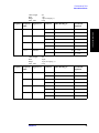
Cable Length: 2m
DUT: 100 pF
Range: 100 pF (Averaging: 1)
Meas. Time:
Long
Frequency
1 kHz
1 MHz
Frequency
Shift
0%
0%
Signal
Level
1000 mV
1000 mV
100 mV
−1 %
+1 %
+2 %
1000 mV
1000 mV
1000 mV
C Copyright 2009 Agilent Technologies
○
Parameter
Test Limit
Cp
±0.085 pF
D
±0.00065
Cp
±0.070 pF
D
±0.00050
Cp
±0.205 pF
D
±0.00185
Cp
±0.070 pF
D
±0.00050
Cp
±0.070 pF
D
±0.00050
Cp
±0.070 pF
D
±0.00050
Test
Result
Measurement
Uncertainty
pF
± 0.019 pF
± 0.00001
pF
± 0.019 pF
± 0.00002
pF
± 0.019 pF
± 0.00003
pF
± 0.019 pF
± 0.00002
pF
± 0.019 pF
± 0.00002
pF
± 0.019 pF
± 0.00002
Cable Length: 2m
DUT: 100 pF
Range: 220 pF (Averaging: 1)
Meas. Time:
Long
Frequency
1 MHz
Frequency
Shift
0%
−1 %
+1 %
+2 %
Signal
Level
1000 mV
1000 mV
1000 mV
1000 mV
Parameter
Test Limit
Cp
±0.088 pF
D
±0.00068
Cp
±0.088 pF
D
±0.00068
Cp
±0.088 pF
D
±0.00068
Cp
±0.088 pF
D
±0.00068
Test
Result
Measurement
Uncertainty
pF
± 0.019 pF
± 0.00002
pF
± 0.019 pF
± 0.00002
pF
± 0.019 pF
± 0.00002
pF
± 0.019 pF
± 0.00002
Cable Length: 2m
DUT: 100 pF
Range: 470 pF (Averaging: 1)
Meas. Time:
Long
Frequency
1 MHz
Frequency
Shift
0%
−1 %
+1 %
+2 %
Signal
Level
1000 mV
1000 mV
1000 mV
1000 mV
C Copyright 2009 Agilent Technologies
○
Parameter
Test Limit
Cp
±0.125 pF
D
±0.00105
Cp
±0.125 pF
D
±0.00105
Cp
±0.125 pF
D
±0.00105
Cp
±0.125 pF
D
±0.00105
Test
Result
Measurement
Uncertainty
pF
± 0.019 pF
± 0.00002
pF
± 0.019 pF
± 0.00002
pF
± 0.019 pF
± 0.00002
pF
± 0.019 pF
± 0.00002
Cable Length: 2m
DUT: 100 pF
Range: 100 pF (Averaging: 1)
Meas. Time:
Short
Frequency
Frequency
Shift
1 MHz
0%
Signal
Level
1000 mV
Parameter
Test Limit
Cp
±0.085 pF
D
±0.00065
Test
Result
Measurement
Uncertainty
pF
± 0.019 pF
± 0.00002
Cable Length: 2m
DUT: 1000 pF
Range: 1 nF(Averaging: 1)
Meas. Time:
Long
Frequency
1 kHz
1 MHz
Frequency
Shift
0%
0%
−1 %
+1 %
+2 %
Signal
Level
1000 mV
1000 mV
1000 mV
1000 mV
1000 mV
C Copyright 2009 Agilent Technologies
○
Parameter
Test Limit
Cp
±0.70 pF
D
±0.00050
Cp
±0.70 pF
D
±0.00050
Cp
±0.70 pF
D
±0.00050
Cp
±0.70 pF
D
±0.00050
Cp
±0.70 pF
D
±0.00050
Test
Result
Measurement
Uncertainty
pF
± 0.20 pF
± 0.00003
pF
± 0.21 pF
± 0.00002
pF
± 0.21 pF
± 0.00002
pF
± 0.21 pF
± 0.00002
pF
± 0.21 pF
± 0.00002
Cable Length: 2m
DUT: 0.01 μF
Range: 10 nF(Averaging: 1)
Meas. Time:
Long
Frequency
1 kHz
Frequency
Shift
0%
Signal
Level
1000 mV
Parameter
Test Limit
Cp
±0.0070 nF
D
±0.00050
Test
Result
Measurement
Uncertainty
nF
± 0.0022 nF
± 0.00001
Cable Length: 2m
DUT: 0.1 μF
Range: 100 nF(Averaging: 1)
Meas. Time:
Long
Frequency
1 kHz
Frequency
Shift
0%
Signal
Level
1000 mV
100 mV
Parameter
Test Limit
Cp
±0.070 nF
D
±0.00050
Cp
±0.205 nF
D
±0.00185
Test
Result
Measurement
Uncertainty
nF
± 0.022 nF
± 0.00001
nF
± 0.022 nF
± 0.00002
Cable Length: 2m
DUT: 0.1 μF
Range: 220 nF(Averaging: 1)
Meas. Time:
Long
Frequency
1 kHz
Frequency
Shift
0%
Signal
Level
1000 mV
C Copyright 2009 Agilent Technologies
○
Parameter
Test Limit
Cp
±0.088 nF
D
±0.00068
Test
Result
Measurement
Uncertainty
nF
± 0.022 nF
± 0.00001
Cable Length: 2m
DUT: 0.1 μF
Range: 470 nF(Averaging: 1)
Meas. Time:
Long
Frequency
Frequency
Shift
1 kHz
0%
Signal
Level
1000 mV
Parameter
Test Limit
Cp
±0.125 nF
D
±0.00105
Test
Result
Measurement
Uncertainty
nF
± 0.022 nF
± 0.00001
Cable Length: 2m
DUT: 0.1 μF
Range: 100 nF(Averaging: 1)
Meas. Time:
Short
Frequency
Frequency
Shift
1 kHz
0%
Signal
Level
1000 mV
Parameter
Test Limit
Cp
±0.085 nF
D
±0.00065
Test
Result
Measurement
Uncertainty
nF
± 0.022 nF
± 0.00001
Cable Length: 2m
DUT: 1 μF
Range: 1 μF (Averaging: 1)
Meas. Time:
Long
Frequency
1 kHz
Frequency
Shift
0%
Signal
Level
1000 mV
C Copyright 2009 Agilent Technologies
○
Parameter
Test Limit
Cp
±0.00070 μF
D
±0.00050
Test
Result
Measurement
Uncertainty
μF
± 0.00022 μF
± 0.00002
Cable Length: 2m
DUT: 10 μF
Range: 10 μF (Averaging: 1)
Meas. Time:
Long
Frequency
1 kHz
Frequency
Shift
0%
Signal
Level
1000 mV
Parameter
Test Limit
Cp
±0.0070 μF
D
±0.00050
Test
Result
Measurement
Uncertainty
μF
± 0.0022 μF
± 0.00006
Cable Length: 1 m
DUT: 100 pF
Range: 100 pF (Averaging: 1)
Meas. Time:
Long
Frequency
1 MHz
Frequency
Shift
0%
−1 %
+1 %
+2 %
Signal
Level
1000 mV
1000 mV
1000 mV
1000 mV
C Copyright 2009 Agilent Technologies
○
Parameter
Test Limit
Cp
±0.070 pF
D
±0.00050
Cp
±0.070 pF
D
±0.00050
Cp
±0.070 pF
D
±0.00050
Cp
±0.070 pF
D
±0.00050
Test
Result
Measurement
Uncertainty
pF
± 0.019 pF
± 0.00002
pF
± 0.019 pF
± 0.00002
pF
± 0.019 pF
± 0.00002
pF
± 0.019 pF
± 0.00002
Cable Length: 0 m
DUT: 100 pF
Range: 100 pF (Averaging: 1)
Meas. Time:
Long
Frequency
1 MHz
Frequency
Shift
0%
−1 %
+1 %
+2 %
Signal
Level
1000 mV
1000 mV
1000 mV
1000 mV
C Copyright 2009 Agilent Technologies
○
Parameter
Test Limit
Cp
±0.070 pF
D
±0.00050
Cp
±0.070 pF
D
±0.00050
Cp
±0.070 pF
D
±0.00050
Cp
±0.070 pF
D
±0.00050
Test
Result
Measurement
Uncertainty
pF
± 0.019 pF
± 0.00002
pF
± 0.019 pF
± 0.00002
pF
± 0.019 pF
± 0.00002
pF
± 0.019 pF
± 0.00002
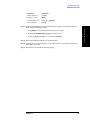
Agilent 4288A 1kHz/1MHz Capacitance Meter
Service Manual
Second Edition
FIRMWARE REVISIONS/SERIAL NUMBERS
This manual applies directly to instruments which has
the firmware revision A.01.10 and the serial number prefix JP1KH.
For additional important information about firmware revisions and serial numbers, see Appendix A.
Manufacturing No. 04288-90200
July 2007
Notices
The information contained in this document is subject to change without notice.
This document contains proprietary information that is protected by copyright. All rights
are reserved. No part of this document may be photocopied, reproduced, or translated to
another language without the prior written consent of Agilent Technologies.
Microsoft®,MS-DOS®,Windows®,Visual C++®,Visual Basic®,VBA® and Excel® are
registered
UNIX is a registered trademark in U.S. and other countries, licensed
exclusively through X/Open Company Limited.
Portions ©Copyright 1996, Microsoft Corporation. All rights reserved.
© Copyright 2001, 2007 Agilent Technologies
Manual Printing History
The manual’s printing date and part number indicate its current edition. The printing date
changes when a new edition is printed. (Minor corrections and updates that are
incorporated at reprint do not cause the date to change.) The manual part number changes
when extensive technical changes are incorporated.
April 2001
First Edition (part number: 04288-90100)
July 2007
Second Edition (part number: 04288-90200)
2
Safety Summary
The following general safety precautions must be observed during all phases of operation,
service, and repair of this instrument. Failure to comply with these precautions or with
specific WARNINGS elsewhere in this manual may impair the protection provided by the
equipment. In addition it violates safety standards of design, manufacture, and intended use
of the instrument.
Agilent Technologies assumes no liability for the customer’s failure to comply with these
requirements.
NOTE
4288A comply with INSTALLATION CATEGORY II and POLLUTION DEGREE 2 in
IEC61010-1. 4288A are INDOOR USE product.
NOTE
LEDs in 4288A are Class 1 in accordance with IEC60825-1.
CLASS 1 LED PRODUCT
•
Ground The Instrument
To avoid electric shock hazard, the instrument chassis and cabinet must be connected to
a safety earth ground by the supplied power cable with earth blade.
•
DO NOT Operate In An Explosive Atmosphere
Do not operate the instrument in the presence of flammable gasses or fumes. Operation
of any electrical instrument in such an environment constitutes a definite safety hazard.
•
Keep Away From Live Circuits
Operating personnel must not remove instrument covers. Component replacement and
internal adjustments must be made by qualified maintenance personnel. Do not replace
components with the power cable connected. Under certain conditions, dangerous
voltages may exist even with the power cable removed. To avoid injuries, always
disconnect power and discharge circuits before touching them.
•
DO NOT Service Or Adjust Alone
Do not attempt internal service or adjustment unless another person, capable of
rendering first aid and resuscitation, is present.
•
DO NOT Substitute Parts Or Modify Instrument
Because of the danger of introducing additional hazards, do not install substitute parts
or perform unauthorized modifications to the instrument. Return the instrument to a
Agilent Technologies Sales and Service Office for service and repair to ensure that
safety features are maintained.
•
Dangerous Procedure Warnings
Warnings, such as the example below, precede potentially dangerous procedures
throughout this manual. Instructions contained in the warnings must be followed.
WARNING
Dangerous voltages, capable of causing death, are presenting this instrument. Use
extreme caution when handling, testing, and adjusting this instrument.
3
Safety Symbol
General definitions of safety symbols used on the instrument or in manuals are listed
below.
Instruction Manual symbol: the product is marked with this symbol when it is necessary for
the user to refer to the instrument manual.
Alternating current.
Direct current.
On (Supply).
Off (Supply).
In position of push-button switch.
Out position of push-button switch.
Frame (or chassis) terminal. A connection to the frame (chassis) of the equipment which
normally include all exposed metal structure.
WARNING
This warning sign denotes a hazard. It calls attention to a procedure, practice,
condition or the like, which, if not correctly performed or adhered to, could result in
injury or death to personnel.
CAUTION
This Caution sign denotes a hazard. It calls attention to a procedure, practice, condition or
the like, which, if not correctly performed or adhered to, could result in damage to or
destruction of part or all of the product.
NOTE
Note denotes important information. It calls attention to a procedure, practice, condition or
the like, which is essential to highlight.
Certification
Agilent Technologies certifies that this product met its published specifications at the time
of shipment from the factory. Agilent Technologies further certifies that its calibration
measurements are traceable to the United States National Institute of Standards and
Technology, to the extent allowed by the Institution’s calibration facility, or to the
calibration facilities of other International Standards Organization members.
4
Warranty
This Agilent Technologies instrument product is warranted against defects in material and
workmanship for a period corresponding to the individual warranty periods of its
component products. Instruments are warranted for a period of one year. Fixtures and
adapters are warranted for a period of 90 days. During the warranty period, Agilent
Technologies Company will, at its option, either repair or replace products that prove to be
defective.
For warranty service or repair, this product must be returned to a service facility designated
by Agilent Technologies. Buyer shall prepay shipping charges to Agilent Technologies and
Agilent Technologies shall pay shipping charges to return the product to Buyer. However,
Buyer shall pay all shipping charges, duties, and taxes for products returned to Agilent
Technologies from another country.
Agilent Technologies warrants that its software and firmware designated by Agilent
Technologies for use with an instrument will execute its programming instruction when
property installed on that instrument. Agilent Technologies does not warrant that the
operation of the instrument, or software, or firmware will be uninterrupted or error free.
Limitation of Warranty
The foregoing warranty shall not apply to defects resulting from improper or inadequate
maintenance by Buyer, Buyer-supplied software or interfacing, unauthorized modification
or misuse, operation outside the environmental specifications for the product, or improper
site preparation or maintenance.
IMPORTANT
No other warranty is expressed or implied. Agilent Technologies specifically disclaims the
implied warranties of merchantability and fitness for a particular purpose.
Exclusive Remedies
The remedies provided herein are buyer’s sole and exclusive remedies. Agilent
Technologies shall not be liable for any direct, indirect, special, incidental, or
consequential damages, whether based on contract, tort, or any other legal theory.
5
Assistance
Product maintenance agreements and other customer assistance agreements are available
for Agilent Technologies products.
For any assistance, contact your nearest Agilent Technologies Sales and Service Office.
Addresses are provided at the back of this manual.
Typeface Conventions
Bold
Boldface type is used when a term is defined. For
example: icons are symbols.
Italic
Italic type is used for emphasis and for titles of
manuals and other publications.
[Hardkey]
Indicates a hardkey labeled “Hardkey.”
Softkey
Indicates a softkey labeled “Softkey.”
[Hardkey] - Softkey1 - Softkey2
Indicates keystrokes [Hardkey] - Softkey1 Softkey2.
4288A Documentation Map
The following manuals are available for the 4288A.
•
Operation Manual (Agilent P/N: 04288-900x0)
Most of basic information necessary for using 4288A is described in this manual. It
includes the way of installation, preparation, measurement operation including
calibration, performances (specifications), key definitions, and error messages. For
GPIB programming, see the Programming Manual together with “HP Instrument
BASIC User's Handbook”.
•
Programming Manual (Agilent P/N: 04288-900x1)
The Programming Manual shows how to write and use BASIC program to control the
4288A and describes how HP Instrument BASIC works with the analyzer.
•
Service Manual (Agilent P/N: 04288-90x00, Supplied as a service part)
This manual describes how to adjust and repair the 4288A, and how to carry out
performance tests. This manual is supplied as a service part.
NOTE
The number position shown by “x” in the part numbers above indicates the edition number.
6
Contents
1. General Information
Organization of Service Manual . . . . . . . . . . . . . . . . . . . . . . . . . . . . . . . . . . . . . . . . . . . . . . . . . . . . . . . . . . 12
Instruments Covered by This Manual. . . . . . . . . . . . . . . . . . . . . . . . . . . . . . . . . . . . . . . . . . . . . . . . . . . . . . 13
Required Equipment . . . . . . . . . . . . . . . . . . . . . . . . . . . . . . . . . . . . . . . . . . . . . . . . . . . . . . . . . . . . . . . . . . . 14
2. Performance Test
Test Equipment . . . . . . . . . . . . . . . . . . . . . . . . . . . . . . . . . . . . . . . . . . . . . . . . . . . . . . . . . . . . . . . . . . . . . . . 16
Performance Test . . . . . . . . . . . . . . . . . . . . . . . . . . . . . . . . . . . . . . . . . . . . . . . . . . . . . . . . . . . . . . . . . . . . . 17
Introduction . . . . . . . . . . . . . . . . . . . . . . . . . . . . . . . . . . . . . . . . . . . . . . . . . . . . . . . . . . . . . . . . . . . . . . . . 17
Frequency Accuracy Test . . . . . . . . . . . . . . . . . . . . . . . . . . . . . . . . . . . . . . . . . . . . . . . . . . . . . . . . . . . . . 18
Signal Level Accuracy Test. . . . . . . . . . . . . . . . . . . . . . . . . . . . . . . . . . . . . . . . . . . . . . . . . . . . . . . . . . . . 20
Capacitance Measurement Accuracy Test. . . . . . . . . . . . . . . . . . . . . . . . . . . . . . . . . . . . . . . . . . . . . . . . . 23
Function Test. . . . . . . . . . . . . . . . . . . . . . . . . . . . . . . . . . . . . . . . . . . . . . . . . . . . . . . . . . . . . . . . . . . . . . . . . 28
Signal Level Monitor Accuracy Test . . . . . . . . . . . . . . . . . . . . . . . . . . . . . . . . . . . . . . . . . . . . . . . . . . . . 28
Handler Interface and Scanner Interface Test . . . . . . . . . . . . . . . . . . . . . . . . . . . . . . . . . . . . . . . . . . . . . . 30
Calculation Sheet . . . . . . . . . . . . . . . . . . . . . . . . . . . . . . . . . . . . . . . . . . . . . . . . . . . . . . . . . . . . . . . . . . . . . 38
Performance Test. . . . . . . . . . . . . . . . . . . . . . . . . . . . . . . . . . . . . . . . . . . . . . . . . . . . . . . . . . . . . . . . . . . . 38
Function Test . . . . . . . . . . . . . . . . . . . . . . . . . . . . . . . . . . . . . . . . . . . . . . . . . . . . . . . . . . . . . . . . . . . . . . . 47
Test Record . . . . . . . . . . . . . . . . . . . . . . . . . . . . . . . . . . . . . . . . . . . . . . . . . . . . . . . . . . . . . . . . . . . . . . . . . . 48
Performance Test Record . . . . . . . . . . . . . . . . . . . . . . . . . . . . . . . . . . . . . . . . . . . . . . . . . . . . . . . . . . . . . 48
Function Test Record . . . . . . . . . . . . . . . . . . . . . . . . . . . . . . . . . . . . . . . . . . . . . . . . . . . . . . . . . . . . . . . . 57
3. Adjustment
Safety Considerations . . . . . . . . . . . . . . . . . . . . . . . . . . . . . . . . . . . . . . . . . . . . . . . . . . . . . . . . . . . . . . . . . . 60
Required Controller . . . . . . . . . . . . . . . . . . . . . . . . . . . . . . . . . . . . . . . . . . . . . . . . . . . . . . . . . . . . . . . . . . . 60
Required Equipment . . . . . . . . . . . . . . . . . . . . . . . . . . . . . . . . . . . . . . . . . . . . . . . . . . . . . . . . . . . . . . . . . . . 60
Warm-up for Adjustment . . . . . . . . . . . . . . . . . . . . . . . . . . . . . . . . . . . . . . . . . . . . . . . . . . . . . . . . . . . . . . . 60
Order of Adjustment . . . . . . . . . . . . . . . . . . . . . . . . . . . . . . . . . . . . . . . . . . . . . . . . . . . . . . . . . . . . . . . . . . . 61
Preparation for using the Adjustment Program . . . . . . . . . . . . . . . . . . . . . . . . . . . . . . . . . . . . . . . . . . . . . . 62
Installing an GPIB Card (82340, 82341 or 82350) . . . . . . . . . . . . . . . . . . . . . . . . . . . . . . . . . . . . . . . . . . 62
Installing Agilent VEE for Personal Computer. . . . . . . . . . . . . . . . . . . . . . . . . . . . . . . . . . . . . . . . . . . . . 62
Installing Adjustment Program into Your PC . . . . . . . . . . . . . . . . . . . . . . . . . . . . . . . . . . . . . . . . . . . . . . 62
Equipment Setup . . . . . . . . . . . . . . . . . . . . . . . . . . . . . . . . . . . . . . . . . . . . . . . . . . . . . . . . . . . . . . . . . . . . 62
Running the Adjustment Program . . . . . . . . . . . . . . . . . . . . . . . . . . . . . . . . . . . . . . . . . . . . . . . . . . . . . . . . 63
Correction Constant Initialization. . . . . . . . . . . . . . . . . . . . . . . . . . . . . . . . . . . . . . . . . . . . . . . . . . . . . . . . . 66
Required Equipment . . . . . . . . . . . . . . . . . . . . . . . . . . . . . . . . . . . . . . . . . . . . . . . . . . . . . . . . . . . . . . . . . 66
Procedure. . . . . . . . . . . . . . . . . . . . . . . . . . . . . . . . . . . . . . . . . . . . . . . . . . . . . . . . . . . . . . . . . . . . . . . . . . 66
Voltage Monitor Correction Constants . . . . . . . . . . . . . . . . . . . . . . . . . . . . . . . . . . . . . . . . . . . . . . . . . . . . . 67
Required Equipment . . . . . . . . . . . . . . . . . . . . . . . . . . . . . . . . . . . . . . . . . . . . . . . . . . . . . . . . . . . . . . . . . 67
Procedure. . . . . . . . . . . . . . . . . . . . . . . . . . . . . . . . . . . . . . . . . . . . . . . . . . . . . . . . . . . . . . . . . . . . . . . . . . 67
Source DC offset Correction Constants . . . . . . . . . . . . . . . . . . . . . . . . . . . . . . . . . . . . . . . . . . . . . . . . . . . . 68
Required Equipment . . . . . . . . . . . . . . . . . . . . . . . . . . . . . . . . . . . . . . . . . . . . . . . . . . . . . . . . . . . . . . . . . 68
Procedure. . . . . . . . . . . . . . . . . . . . . . . . . . . . . . . . . . . . . . . . . . . . . . . . . . . . . . . . . . . . . . . . . . . . . . . . . . 68
Source Level Correction Constants . . . . . . . . . . . . . . . . . . . . . . . . . . . . . . . . . . . . . . . . . . . . . . . . . . . . . . . 69
Required Equipment . . . . . . . . . . . . . . . . . . . . . . . . . . . . . . . . . . . . . . . . . . . . . . . . . . . . . . . . . . . . . . . . . 69
Procedure. . . . . . . . . . . . . . . . . . . . . . . . . . . . . . . . . . . . . . . . . . . . . . . . . . . . . . . . . . . . . . . . . . . . . . . . . . 69
Current Sense Offset Correction Constants . . . . . . . . . . . . . . . . . . . . . . . . . . . . . . . . . . . . . . . . . . . . . . . . . 70
Required Equipment . . . . . . . . . . . . . . . . . . . . . . . . . . . . . . . . . . . . . . . . . . . . . . . . . . . . . . . . . . . . . . . . . 70
7
Contents
Procedure . . . . . . . . . . . . . . . . . . . . . . . . . . . . . . . . . . . . . . . . . . . . . . . . . . . . . . . . . . . . . . . . . . . . . . . . .
Modem Offset Correction Constants . . . . . . . . . . . . . . . . . . . . . . . . . . . . . . . . . . . . . . . . . . . . . . . . . . . . . .
Required Equipment . . . . . . . . . . . . . . . . . . . . . . . . . . . . . . . . . . . . . . . . . . . . . . . . . . . . . . . . . . . . . . . . .
Procedure . . . . . . . . . . . . . . . . . . . . . . . . . . . . . . . . . . . . . . . . . . . . . . . . . . . . . . . . . . . . . . . . . . . . . . . . .
Linearity Correction Constants. . . . . . . . . . . . . . . . . . . . . . . . . . . . . . . . . . . . . . . . . . . . . . . . . . . . . . . . . . .
Required Equipment . . . . . . . . . . . . . . . . . . . . . . . . . . . . . . . . . . . . . . . . . . . . . . . . . . . . . . . . . . . . . . . . .
Procedure . . . . . . . . . . . . . . . . . . . . . . . . . . . . . . . . . . . . . . . . . . . . . . . . . . . . . . . . . . . . . . . . . . . . . . . . .
VRD Gain Correction Constants . . . . . . . . . . . . . . . . . . . . . . . . . . . . . . . . . . . . . . . . . . . . . . . . . . . . . . . . .
Required Equipment . . . . . . . . . . . . . . . . . . . . . . . . . . . . . . . . . . . . . . . . . . . . . . . . . . . . . . . . . . . . . . . . .
Procedure . . . . . . . . . . . . . . . . . . . . . . . . . . . . . . . . . . . . . . . . . . . . . . . . . . . . . . . . . . . . . . . . . . . . . . . . .
TRD Range Resistors Correction Constants . . . . . . . . . . . . . . . . . . . . . . . . . . . . . . . . . . . . . . . . . . . . . . . .
Required Equipment . . . . . . . . . . . . . . . . . . . . . . . . . . . . . . . . . . . . . . . . . . . . . . . . . . . . . . . . . . . . . . . . .
Procedure . . . . . . . . . . . . . . . . . . . . . . . . . . . . . . . . . . . . . . . . . . . . . . . . . . . . . . . . . . . . . . . . . . . . . . . . .
Impedance Correction Constants . . . . . . . . . . . . . . . . . . . . . . . . . . . . . . . . . . . . . . . . . . . . . . . . . . . . . . . . .
Required Equipment . . . . . . . . . . . . . . . . . . . . . . . . . . . . . . . . . . . . . . . . . . . . . . . . . . . . . . . . . . . . . . . . .
Procedure . . . . . . . . . . . . . . . . . . . . . . . . . . . . . . . . . . . . . . . . . . . . . . . . . . . . . . . . . . . . . . . . . . . . . . . . .
After Adjustment . . . . . . . . . . . . . . . . . . . . . . . . . . . . . . . . . . . . . . . . . . . . . . . . . . . . . . . . . . . . . . . . . . . . .
Required Equipment . . . . . . . . . . . . . . . . . . . . . . . . . . . . . . . . . . . . . . . . . . . . . . . . . . . . . . . . . . . . . . . . .
Procedure . . . . . . . . . . . . . . . . . . . . . . . . . . . . . . . . . . . . . . . . . . . . . . . . . . . . . . . . . . . . . . . . . . . . . . . . .
70
71
71
71
72
72
72
73
73
73
74
74
74
75
75
75
77
77
77
4. Troubleshooting
Introduction . . . . . . . . . . . . . . . . . . . . . . . . . . . . . . . . . . . . . . . . . . . . . . . . . . . . . . . . . . . . . . . . . . . . . . . . .
Safety . . . . . . . . . . . . . . . . . . . . . . . . . . . . . . . . . . . . . . . . . . . . . . . . . . . . . . . . . . . . . . . . . . . . . . . . . . . .
ESD Precautions . . . . . . . . . . . . . . . . . . . . . . . . . . . . . . . . . . . . . . . . . . . . . . . . . . . . . . . . . . . . . . . . . . . .
Required Equipment . . . . . . . . . . . . . . . . . . . . . . . . . . . . . . . . . . . . . . . . . . . . . . . . . . . . . . . . . . . . . . . . .
Trouble Isolation. . . . . . . . . . . . . . . . . . . . . . . . . . . . . . . . . . . . . . . . . . . . . . . . . . . . . . . . . . . . . . . . . . . . . .
Trouble Isolation Flowchart . . . . . . . . . . . . . . . . . . . . . . . . . . . . . . . . . . . . . . . . . . . . . . . . . . . . . . . . . . .
Check 1: Power on self-test . . . . . . . . . . . . . . . . . . . . . . . . . . . . . . . . . . . . . . . . . . . . . . . . . . . . . . . . . . .
Check 2: Power Supply Check . . . . . . . . . . . . . . . . . . . . . . . . . . . . . . . . . . . . . . . . . . . . . . . . . . . . . . . . .
Check 3: Fan Check . . . . . . . . . . . . . . . . . . . . . . . . . . . . . . . . . . . . . . . . . . . . . . . . . . . . . . . . . . . . . . . . .
Check 4: LCD backlight . . . . . . . . . . . . . . . . . . . . . . . . . . . . . . . . . . . . . . . . . . . . . . . . . . . . . . . . . . . . . .
Check 5: External Test . . . . . . . . . . . . . . . . . . . . . . . . . . . . . . . . . . . . . . . . . . . . . . . . . . . . . . . . . . . . . . .
Check 6: Digital Trouble Isolation . . . . . . . . . . . . . . . . . . . . . . . . . . . . . . . . . . . . . . . . . . . . . . . . . . . . . .
Service Functions . . . . . . . . . . . . . . . . . . . . . . . . . . . . . . . . . . . . . . . . . . . . . . . . . . . . . . . . . . . . . . . . . . . . .
Firmware Revision Confirmation . . . . . . . . . . . . . . . . . . . . . . . . . . . . . . . . . . . . . . . . . . . . . . . . . . . . . . .
Internal Test . . . . . . . . . . . . . . . . . . . . . . . . . . . . . . . . . . . . . . . . . . . . . . . . . . . . . . . . . . . . . . . . . . . . . . .
External test . . . . . . . . . . . . . . . . . . . . . . . . . . . . . . . . . . . . . . . . . . . . . . . . . . . . . . . . . . . . . . . . . . . . . . .
Power On Self-test . . . . . . . . . . . . . . . . . . . . . . . . . . . . . . . . . . . . . . . . . . . . . . . . . . . . . . . . . . . . . . . . . .
Front Panel Key Test. . . . . . . . . . . . . . . . . . . . . . . . . . . . . . . . . . . . . . . . . . . . . . . . . . . . . . . . . . . . . . . . .
Interface Test. . . . . . . . . . . . . . . . . . . . . . . . . . . . . . . . . . . . . . . . . . . . . . . . . . . . . . . . . . . . . . . . . . . . . . .
Handler Interface Test. . . . . . . . . . . . . . . . . . . . . . . . . . . . . . . . . . . . . . . . . . . . . . . . . . . . . . . . . . . . . . . .
Scanner Interface Test. . . . . . . . . . . . . . . . . . . . . . . . . . . . . . . . . . . . . . . . . . . . . . . . . . . . . . . . . . . . . . . .
Memory Test . . . . . . . . . . . . . . . . . . . . . . . . . . . . . . . . . . . . . . . . . . . . . . . . . . . . . . . . . . . . . . . . . . . . . . .
80
80
80
80
81
81
82
82
83
83
84
84
85
85
85
86
91
91
92
92
92
92
5. Theory of Operation
Overall Operation . . . . . . . . . . . . . . . . . . . . . . . . . . . . . . . . . . . . . . . . . . . . . . . . . . . . . . . . . . . . . . . . . . . . . 96
Overall Operation . . . . . . . . . . . . . . . . . . . . . . . . . . . . . . . . . . . . . . . . . . . . . . . . . . . . . . . . . . . . . . . . . . . 96
Function Groups . . . . . . . . . . . . . . . . . . . . . . . . . . . . . . . . . . . . . . . . . . . . . . . . . . . . . . . . . . . . . . . . . . . . 96
8
Contents
Power Supply Operation . . . . . . . . . . . . . . . . . . . . . . . . . . . . . . . . . . . . . . . . . . . . . . . . . . . . . . . . . . . . . . . . 98
Line Power Module. . . . . . . . . . . . . . . . . . . . . . . . . . . . . . . . . . . . . . . . . . . . . . . . . . . . . . . . . . . . . . . . . . 98
Pre-regulator . . . . . . . . . . . . . . . . . . . . . . . . . . . . . . . . . . . . . . . . . . . . . . . . . . . . . . . . . . . . . . . . . . . . . . . 98
Digital Control Operation . . . . . . . . . . . . . . . . . . . . . . . . . . . . . . . . . . . . . . . . . . . . . . . . . . . . . . . . . . . . . . . 99
A1 Main Board . . . . . . . . . . . . . . . . . . . . . . . . . . . . . . . . . . . . . . . . . . . . . . . . . . . . . . . . . . . . . . . . . . . . . 99
Front Keyboard . . . . . . . . . . . . . . . . . . . . . . . . . . . . . . . . . . . . . . . . . . . . . . . . . . . . . . . . . . . . . . . . . . . . 100
LCD. . . . . . . . . . . . . . . . . . . . . . . . . . . . . . . . . . . . . . . . . . . . . . . . . . . . . . . . . . . . . . . . . . . . . . . . . . . . . 100
Analog Circuit Operation . . . . . . . . . . . . . . . . . . . . . . . . . . . . . . . . . . . . . . . . . . . . . . . . . . . . . . . . . . . . . . 101
Source Theory . . . . . . . . . . . . . . . . . . . . . . . . . . . . . . . . . . . . . . . . . . . . . . . . . . . . . . . . . . . . . . . . . . . . . 102
Transducer Theory . . . . . . . . . . . . . . . . . . . . . . . . . . . . . . . . . . . . . . . . . . . . . . . . . . . . . . . . . . . . . . . . . 103
Vector Ratio Detector . . . . . . . . . . . . . . . . . . . . . . . . . . . . . . . . . . . . . . . . . . . . . . . . . . . . . . . . . . . . . . . 104
6. Assembly Replacement
Safety . . . . . . . . . . . . . . . . . . . . . . . . . . . . . . . . . . . . . . . . . . . . . . . . . . . . . . . . . . . . . . . . . . . . . . . . . . . . . 106
ESD Precautions . . . . . . . . . . . . . . . . . . . . . . . . . . . . . . . . . . . . . . . . . . . . . . . . . . . . . . . . . . . . . . . . . . . . . 106
Ordering Information . . . . . . . . . . . . . . . . . . . . . . . . . . . . . . . . . . . . . . . . . . . . . . . . . . . . . . . . . . . . . . . . . 106
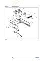
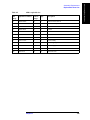
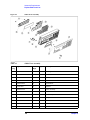
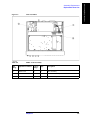
Exchange Assemblies . . . . . . . . . . . . . . . . . . . . . . . . . . . . . . . . . . . . . . . . . . . . . . . . . . . . . . . . . . . . . . . . . 106
Replaceable Parts List. . . . . . . . . . . . . . . . . . . . . . . . . . . . . . . . . . . . . . . . . . . . . . . . . . . . . . . . . . . . . . . . . 107
Disassembly Procedure. . . . . . . . . . . . . . . . . . . . . . . . . . . . . . . . . . . . . . . . . . . . . . . . . . . . . . . . . . . . . . . . 114
Cover Removal . . . . . . . . . . . . . . . . . . . . . . . . . . . . . . . . . . . . . . . . . . . . . . . . . . . . . . . . . . . . . . . . . . . . 114
Front Assembly Removal . . . . . . . . . . . . . . . . . . . . . . . . . . . . . . . . . . . . . . . . . . . . . . . . . . . . . . . . . . . . 114
A1 Main Board Removal . . . . . . . . . . . . . . . . . . . . . . . . . . . . . . . . . . . . . . . . . . . . . . . . . . . . . . . . . . . . 116
Power Supply Assembly Removal . . . . . . . . . . . . . . . . . . . . . . . . . . . . . . . . . . . . . . . . . . . . . . . . . . . . . 116
Fan Assembly Removal . . . . . . . . . . . . . . . . . . . . . . . . . . . . . . . . . . . . . . . . . . . . . . . . . . . . . . . . . . . . . 118
Power Switch Replacement. . . . . . . . . . . . . . . . . . . . . . . . . . . . . . . . . . . . . . . . . . . . . . . . . . . . . . . . . . . 119
LCD Assembly Removal . . . . . . . . . . . . . . . . . . . . . . . . . . . . . . . . . . . . . . . . . . . . . . . . . . . . . . . . . . . . 119
Keyboard Assembly Removal. . . . . . . . . . . . . . . . . . . . . . . . . . . . . . . . . . . . . . . . . . . . . . . . . . . . . . . . . 120
Post Repair Procedure. . . . . . . . . . . . . . . . . . . . . . . . . . . . . . . . . . . . . . . . . . . . . . . . . . . . . . . . . . . . . . . . . 122
Firmware Installation . . . . . . . . . . . . . . . . . . . . . . . . . . . . . . . . . . . . . . . . . . . . . . . . . . . . . . . . . . . . . . . . . 123
Required Controller. . . . . . . . . . . . . . . . . . . . . . . . . . . . . . . . . . . . . . . . . . . . . . . . . . . . . . . . . . . . . . . . . 123
Installation Program and Firmware. . . . . . . . . . . . . . . . . . . . . . . . . . . . . . . . . . . . . . . . . . . . . . . . . . . . . 123
Installation procedure . . . . . . . . . . . . . . . . . . . . . . . . . . . . . . . . . . . . . . . . . . . . . . . . . . . . . . . . . . . . . . . 123
A. Manual Changes
Manual Changes . . . . . . . . . . . . . . . . . . . . . . . . . . . . . . . . . . . . . . . . . . . . . . . . . . . . . . . . . . . . . . . . . . . . . 126
B. Power Requirement
Replacing Fuse . . . . . . . . . . . . . . . . . . . . . . . . . . . . . . . . . . . . . . . . . . . . . . . . . . . . . . . . . . . . . . . . . . . . . . 128
Fuse Selection . . . . . . . . . . . . . . . . . . . . . . . . . . . . . . . . . . . . . . . . . . . . . . . . . . . . . . . . . . . . . . . . . . . . . 128
Setting up the fuse . . . . . . . . . . . . . . . . . . . . . . . . . . . . . . . . . . . . . . . . . . . . . . . . . . . . . . . . . . . . . . . . . . 128
Power Requirements . . . . . . . . . . . . . . . . . . . . . . . . . . . . . . . . . . . . . . . . . . . . . . . . . . . . . . . . . . . . . . . . . . 129
Power Cable . . . . . . . . . . . . . . . . . . . . . . . . . . . . . . . . . . . . . . . . . . . . . . . . . . . . . . . . . . . . . . . . . . . . . . 129
C. Error Messages
Error messages (alphabetical order) . . . . . . . . . . . . . . . . . . . . . . . . . . . . . . . . . . . . . . . . . . . . . . . . . . . . . . 132
Warning messages (WARNING) . . . . . . . . . . . . . . . . . . . . . . . . . . . . . . . . . . . . . . . . . . . . . . . . . . . . . . . . 141
9
Contents
10
1. General Information
2. Chapter Title
3. Chapter Title
4. Chapter Title
1
General Information
5. Chapter Title
This Service Manual is a guide to servicing the 4288A 1kHz/1MHz Capacitance Meter.
The Service Manual provides information about performance test, adjustment,
troubleshooting, and repairing the 4288A.
11
General Information
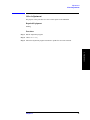
Organization of Service Manual
Organization of Service Manual
This manual consists of the major chapters listed below. This section describes the names
of the chapters and the content of each chapter.
•
“Performance Test” provides procedures for executing performance test and function
test for 4288A.
•
“Adjustment” provides procedures for adjusting the 4288A after repair or replacement
of an assembly. All adjustments update the correction constants stored in the EEPROM
on the A1 Main board.
•
“Troubleshooting” provides troubleshooting procedures to isolate faulty assembly. This
chapter also contains the theory of operation and explanation of service functions.
•
“Theory of Operation” describes the general overall operation of the 4288A and the
operation of each assembly.
•
“Assembly Replacement” provides part numbers and illustrations of the replaceable
assemblies and miscellaneous chassis parts. This chapter also contains procedures to
disassemble portions of the 4288A when certain assemblies have to be replaced.
12
Chapter 1
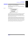
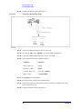
Instruments Covered by This Manual
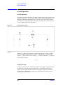
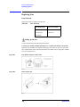
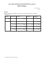
Agilent Technologies uses a two-part, ten-character serial number label (See Figure 1-1)
attached to the instrument’s rear panel. The first five characters are the serial prefix and the
last five digits are the suffix.
Figure 1-1
1. General Information
General Information
Instruments Covered by This Manual
Serial Number Label
2. Chapter Title
In addition to change information, the supplement may contain information for correcting
errors (Errata) in the manual. To keep this manual as current and accurate as possible,
Agilent Technologies recommends that you periodically request the latest Manual Changes
supplement. The supplement for this manual is identified by this manual’s printing data
and is available from Agilent Technologies. If the serial prefix or number of an instrument
is lower than that on the title page of this manual, see Appendix A, Manual Changes. For
information concerning, a serial number prefix that is not listed on the title page or in the
Manual Changes supplement, contact the nearest Agilent Technologies office.
3. Chapter Title
An instrument manufactured after the printing date of this manual may have serial number
prefix that is not listed on the title page. This unlisted serial number prefix indicates the
instrument is different from those described in this manual. The manual for this new
instrument may be accompanied by a yellow Manual Changes supplement or have a
different manual part number. This sheet contains “change information” that explains how
to adapt the manual to the newer instrument.
4. Chapter Title
5. Chapter Title
Chapter 1
13
General Information
Required Equipment
Required Equipment
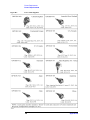
Table 1-1 lists the recommended equipment for performance test, adjustment and
troubleshooting for 4288A.
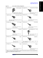
Table 1-1
Recommended Test Equipment
Equipment
Critical Specifications
Recommended Model
Qty.
Use*1
Frequency Counter
Frequency Range: 1 kHz, 1 MHz
Time Base Error < 50 ppm/year
5334B, 53131/2A or
53181A
1
P
Multimeter
No Substitute
3458A
1
P
Standard Capacitor Set
No Substitute
16380A
1
P,A
Standard Capacitor Set
No Substitute
16380C with #001
1
P,A
4TP Open Termination
No Substitute
42090A
1
P,A,T
Test Leads 1 m
No Substitute
16048A
1
P
Test Leads 2 m
No Substitute
16048D
1
P
Handler & Scanner
Interface Tester
No Substitute
04288-65001 or
(04278-65001 and
04278-65301)*2
1
P
Interface Box
No Substitute
04284-65007
1
P
Cables
BNC(m)-BNC(m) Cable, 61 cm
p/n 8120-1839
1
P
Adapter
BNC(f)-BNC(f) Adapter
p/n 1250-1830
4
P
Dual Banana-BNC(f) Adapter
p/n 1251-2277
1
P
*1.P:Performance Test A:Adjustment T:Troubleshooting
*2.Both instruments are required for an alternative to 04288-65001.
14
Chapter 1
1. Chapter Title
2. Performance Test
3. Chapter Title
4. Chapter Title
2
Performance Test
15
5. Chapter Title
This chapter provides the procedure of the performance test and the function test for 4288A
1 kHz/1 MHz Capacitance Meter. These tests are used to verify that the 4288A’s
performance meets its specifications.
Performance Test
Test Equipment
Test Equipment
Table 1-1 on page 14 lists the recommended equipment for Performance Test and Function
Test.
16
Chapter 2
Performance Test
1. Chapter Title
Performance Test
Performance Test
Introduction
Warm Up Time
Allow the 4288A to warm up for at least 30 minutes before you execute any of the
performance tests
2. Performance Test
This section provides the test procedures used to verify that the 4288A’s specifications are
met. The performance tests can also be used for incoming inspection, and for verification
after troubleshooting or adjustment. If the performance tests indicate that the 4288A is
NOT operating within the specified limits, check your test setup, then proceed with
troubleshooting if necessary.
Ambient Conditions
Perform all performance tests in ambient conditions of 23 °C ± 5 °C, ≤ 70% RH.
Performance Test Interval
NOTE
The test interval depends on maintenance of use and the environmental conditions under
which the instrument is used. You may find that the test interval could be shortened or
lengthened; however, such a decision should be based on substantial quantitative data.
3. Chapter Title
The performance test should be performed periodically. The recommended test interval is
12 months.
Performance Test Record and Calculation Sheet
Performance test record lists all test points, acceptable test limits, test result entry columns,
and measurement uncertainties. The listed measurement uncertainties are valid only when
the recommended test equipment is used.
4. Chapter Title
The calculation sheet is used as an aid for recording raw measurement data, and for
calculating the performance test results.
The procedure for using the calculation sheet and performance test record is;
1. Photo copy the calculation sheet.
2. Follow the performance test procedure and record the measurement values, the
4288A’s reading, etc., into the specified column on the calculation sheet.
3. Calculate the test result using the appropriate equation given on the calculation sheet,
and record the test result into the Test Result column of the performance test record.
5. Chapter Title
Chapter 2
17
Performance Test
Performance Test
Frequency Accuracy Test
The 4288A’s frequency is measured with a frequency counter
Specification
Frequency Accuracy: ±0.02 %
Test Equipment
Description
Recommended Model
Test Leads, 2 m
16048D
Frequency Counter
53131A, 53132A,
53181A or 5334B
Interface Box
p/n 04284-65007
BNC(f)-BNC(f) Adapter
p/n 1250-1830, 4ea
BNC(m)-BNC(m) Cable, 61 cm
p/n 8120-1839
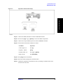
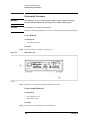
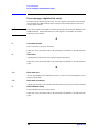
Procedure
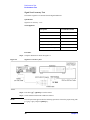
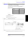
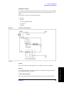
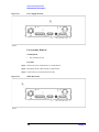
Step 1. Setup the instrument as shown in Figure 2-1.
Figure 2-1
Frequency Accuracy Test
Step 2. Press blue-[.]-[↑→]-[Enter] to reset the 4288A.
Step 3. Set the 4288A measurement condition as follows.
18
Chapter 2
NOTE
The selection menu appears after the following operations. Choose the proper setting with
[←↓] or [↑→] key and press [Enter] key.
Conditions
Operation
Cable Length: 2 m
blue-[2]
Frequency: 1 kHz
[Freq]
Frequency Shift: 0 %
blue-[−]-[↑→]-[Enter]
2. Performance Test
Step 4. Record the frequency counter’s reading to the calculation sheet.
Step 5. Calculate the test result according to the calculation sheet, then record it into the
performance test record.
Step 6. Repeat Step 4 and 5 under the following setting.
Frequency
Frequency
Shift
1 kHz
0%
1 MHz
0%
1. Chapter Title
Performance Test
Performance Test
3. Chapter Title
−1 %
+1 %
+2 %
4. Chapter Title
5. Chapter Title
Chapter 2
19
Performance Test
Performance Test
Signal Level Accuracy Test
The 4288A’s signal level is measured with a digital multimeter.
Specification
Signal Level Accuracy: ±5 %
Test Equipment
Description
Recommended Model
Test Leads, 2 m
16048D
Multimeter
3458A
Interface Box
p/n 04284-65007
BNC(m)-BNC(m) Cable, 61 cm
p/n 8120-1839
BNC(f)-BNC(f) Adapter
p/n 1250-1830, 4ea
BNC(f)-Dual Banana Plug
p/n 1251-2277
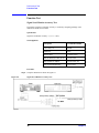
Procedure
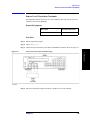
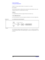
Step 1. Setup the instrument as shown in Figure 2-2.
Figure 2-2
Signal Level Accuracy Test
Step 2. Press blue-[.]-[↑→]-[Enter] to reset the 4288A.
Step 3. Set the 4288A measurement condition as follows.
NOTE
The selection menu appears after the following operations. Choose the proper setting with
[←↓] or [↑→] key and press [Enter] key.
20
Chapter 2
Conditions
Operation
Cable Length: 2 m
blue-[2]
Frequency: 1 kHz
[Freq]
Frequency Shift: 0 %
blue-[−]-[↑→]-[Enter]
Level: 1000 mV
[Level]
2. Performance Test
Step 4. Set the 3458A Multimeter to the Synchronously Sub-sample AC voltage measurement
mode using the following procedure:
1. Chapter Title
Performance Test
Performance Test
1. Press [ACV] key to set the measurement mode to AC voltage.
2. Press S(blue-[N Rdgs/Trig])-[↓]-[↓]-[↓] to display SETACV.
3. Press [→]-[↓]-[↓]-[↓] to display SYNC, then press [Enter].
Step 5. Record the multimeter reading to the calculation sheet.
Step 6. Calculate the test result according to the calculation sheet, and record the result into the
performance test record.
Step 7. Repeat Step 5 and 6 under the following setting.
3. Chapter Title
4. Chapter Title
5. Chapter Title
Chapter 2
21
Performance Test
Performance Test
Frequency
Frequency
Shift
Level
1 kHz
0%
1000 mV
500 mV
300 mV
100 mV
1 MHz
0%
1000 mV
500 mV
300 mV
100 mV
−1 %
1000 mV
500 mV
300 mV
100 mV
+1 %
1000 mV
500 mV
300 mV
100 mV
+2 %
1000 mV
500 mV
300 mV
100 mV
22
Chapter 2
Capacitance Measurement Accuracy Test
The 4288A measures the calibrated standard capacitors at the 4288A’s front panel, and the
measured values are compared with the standards’ listed values.
1. Chapter Title
Performance Test
Performance Test
Specifications
Basic Measurement Accuracy:
±0.07 % (Capacitance)
±0.0005 (Dissipation Factor)
2. Performance Test
NOTE
See the Specifications and Supplemental Informations on the Operation Manual for
details.
Test Equipment
Recommended Model
Test Leads, 1 m
16048A
Test Leads, 2 m
16048D
Standard Capacitor Set
16380A
Standard Capacitor Set
16380C
4TP Open Termination
42090A
BNC(f)-BNC(f) Adapter
p/n 1250-1830, 4ea
3. Chapter Title
Description
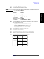
Procedure
Step 1. Record the 16380A and 16380C calibration values into the calculation sheet.
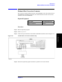
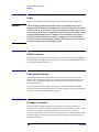
Step 2. Setup the instrument as shown in Figure 2-3.
4. Chapter Title
5. Chapter Title
Chapter 2
23
Performance Test
Performance Test
Figure 2-3
Capacitance Measurement Accuracy Test
Step 3. Press blue-[.]-[↑→]-[Enter] to reset the 4288A.
Step 4. Connect the OPEN termination to the 2 m Test Leads.
Step 5. Press the blue-[4]-[↑→]-[↑→]-[Enter] to execute the OPEN compensation.
Step 6. Connect the 1 pF standard capacitor to the 2 m Test Leads.
Step 7. Set the 4288A measurement condition as follows.
NOTE
The selection menu appears after the following operations. Choose the proper setting with
[←↓] or [↑→] key and press [Enter] key.
Conditions
Operation
Cable Length: 2 m
blue-[2]
Frequency: 1 MHz
[Freq]
Frequency Shift: 0 %
blue-[−]-[↑→]-[Enter]
Level: 1000 mV
[Level]
Meas. Parameter: Pri:Cp Sec:D
[Meas Prmtr]
Range: 1 pF
blue-[Auto/Hold]
Trigger Mode: manual
[Trig Mode]
Meas. Time: Long
[Meas Time]
Averaging: 1
blue-[Meas Time]
Step 8. Press [Trig] to start measurement.
Step 9. Record the 4288A reading in the calculation sheet.
Step 10. Calculate the capacitance measurement accuracy according to calculation sheet, then
record it into the test record.
24
Chapter 2
Step 11. Perform Step 8 and 10 for all setting in the following table.
Standard
Capacitor
Frequency
Level
Meas. Time
Range
Averaging
Frequency
Shift
1 pF
1 MHz
1000 mV
Long
1 pF
1
0%
1. Chapter Title
Performance Test
Performance Test
−1 %
+1 %
+2 %
1 MHz
1000 mV
Long
10 pF
1
2. Performance Test
10 pF
0%
−1 %
+1 %
+2 %
100 pF
1 kHz
1000 mV
Long
100 pF
1
0%
1 MHz
1000 mV
Long
100 pF
1
0%
100 mV
−1 %
1000 mV
+1 %
220 pF
5
3. Chapter Title
+2 %
0%
−1 %
+1 %
+2 %
470 pF
22
0%
−1 %
+1 %
+2 %
100 pF
1
0%
1 kHz
1000 mV
Long
1000 pF
1
0%
1 MHz
1000 mV
Long
1000 pF
1
0%
4. Chapter Title
1000 pF
Short
−1 %
+1 %
+2 %
0.01 μF
1 kHz
1000 mV
Long
10 nF
1
0%
0.1 μF
1 kHz
1000 mV
Long
100 nF
1
0%
220 nF
5
470 nF
22
Short
100 nF
1
100 mV
1000 mV
1 kHz
1000 mV
Long
1 μF
1
0%
10 μF
1 kHz
1000 mV
Long
10 μF
1
0%
Chapter 2
5. Chapter Title
1 μF
25
Performance Test
Performance Test
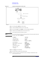
Step 12. Setup the instrument as shown in Figure 2-4.
Figure 2-4
Capacitance Measurement Setup
Step 13. Connect the OPEN termination to the 1 m Test Leads.
Step 14. Press the blue-[4]-[↑→]-[↑→]-[Enter] to execute the OPEN compensation.
Step 15. Connect the 100 pF standard capacitor to the 2 m Test Leads.
Step 16. Set the 4288A measurement condition as follows.
Conditions
Operation
Cable Length: 1 m
blue-[.]
Frequency: 1 MHz
[Freq]
Frequency Shift: 0 %
blue-[−]-[↑→]-[Enter]
Range: 100 pF
blue-[Auto/Hold]
Step 17. Press [Trig] to start measurement.
Step 18. Record the 4288A reading in the calculation sheet.
Step 19. Calculate the capacitance measurement accuracy according to calculation sheet, then
record it in the test record.
Step 20. Setup the instrument as shown in Figure 2-5.
26
Chapter 2
Figure 2-5
Capacitance Measurement Setup
1. Chapter Title
Performance Test
Performance Test
2. Performance Test
3. Chapter Title
Step 21. Connect the OPEN termination to 4288A UNKNOWN terminal.
Step 22. Press the blue-[4]-[↑→]-[↑→]-[Enter] to execute the OPEN compensation.
Step 23. Connect the 100 pF standard capacitor to 4288A UNKNOWN terminal.
Step 24. Set the 4288A measurement condition as follows.
Operation
Cable Length: 0 m
blue-[2]
Frequency: 1 MHz
[Freq]
Frequency Shift: 0 %
blue-[−]-[↑→]-[Enter]
Range: 100 pF
blue-[Auto/Hold]
4. Chapter Title
Conditions
Step 25. Press [Trig] to start measurement.
Step 26. Record the 4288A reading in the calculation sheet.
Step 27. Calculate the capacitance measurement accuracy according to calculation sheet, then
record it in the test record.
5. Chapter Title
Chapter 2
27
Performance Test
Function Test
Function Test
Signal Level Monitor Accuracy Test
The 4288A’s signal level monitor accuracy is verified by comparing readings of the
multimeter and the level monitor.
Specification
Signal Level Monitor Accuracy: ± (3 % + 1 mV)
Test Equipment
Description
Recommended Model
Test Leads, 2 m
16048D
Multimeter
3458A
Interface Box
p/n 04284-65007
BNC(m)-BNC(m) Cable, 61 cm
p/n 8120-1839
BNC(f)-BNC(f) Adapter
p/n 1250-1830, 4ea
BNC(f)-Dual Banana Plug
p/n 1251-2277
Procedure
Step 1. Setup the instrument as shown in Figure 2-6.
Figure 2-6
Signal Level Monitor Accuracy Test
28
Chapter 2
Step 2. Press blue-[.]-[↑→]-[Enter] to reset the 4288A.
Step 3. Set the 4288A measurement condition as follows.
NOTE
1. Chapter Title
Performance Test
Function Test
The selection menu appears after the following operations. Choose the proper setting with
[←↓] or [↑→] key and press [Enter] key.
Operation
Cable Length: 2 m
blue-[2]
Frequency: 1 kHz
[Freq]
Frequency Shift: 0 %
blue-[−]-[↑→]-[Enter]
Level: 1000 mV
[Level]
Trigger Mode: manual
[Trig Mode]
Level Monitor: V
blue-[Show Setting]-[↑→]-[Enter]
2. Performance Test
Conditions
Step 4. Set the 3458A Multimeter to the Synchronously Sub-sample AC voltage measurement
mode using the following procedure:
1. Press [ACV] key to set the measurement mode to AC voltage.
3. Chapter Title
2. Press S(blue-[N Rdgs/Trig])-[↓]-[↓]-[↓] to display SETACV.
3. Press [→]-[↓]-[↓]-[↓] to display SYNC, then press [Enter].
Step 5. Record the Multimeter reading in the calculation sheet.
Step 6. Press [Trig] key to start measurement.
Step 7. Record the 4288A reading of the voltage monitor in the calculation sheet.
Step 8. Calculate the signal level monitor accuracy according to calculation sheet.
Step 9. Perform the step 5 to 8 for all setting in the following table
Frequency
Shift
Level
1 kHz
0%
1000 mV
1 MHz
0%
1000 mV
−1 %
1000 mV
+1 %
1000 mV
+2 %
1000 mV
4. Chapter Title
Frequency
5. Chapter Title
Chapter 2
29
Performance Test
Function Test
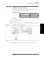
Handler Interface and Scanner Interface Test
The 4288A’s handler interface function and scanner interface function are tested using the
built-in self-test and the handler and scanner interface tester.
Test Equipment
Description
Recommended Model
Handler & Scanner I/F Tester
p/n 04288-65001*1
*1.Handler Interface Simulator (04278-65001) and Scanner
Interface Simulator (04278-65301) can be used for substitute,
Procedure with 04288-65001
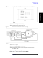
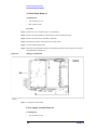
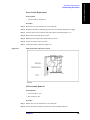
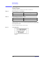
Step 1. Turn off the 4288A, then remove the screws from the bottom side as shown in Figure 2-7.
Figure 2-7
Removing the screws from the bottom side.
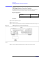
Step 2. Memorize the settings of the jumper(JP1), the bit switchs(S1,S2 and S3) and the
networking resitors(J1,J2,J3).
Step 3. Set these setting to the factory setting as shown in Figure 2-8.
30
Chapter 2
Figure 2-8
Factory Setting of the jumper, the bit switches and the networking resistors
1. Chapter Title
Performance Test
Function Test
2. Performance Test
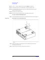
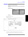
Step 4. Re-assemble the plate removed in Step 1.
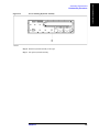
Figure 2-9
3. Chapter Title
Step 5. Setup the instrument as shown in Figure 2-9.
Handler Interface and Scanner Interface Test setup
4. Chapter Title
Step 6. Turn on the 4288A.
Step 7. Press blue-[.]-[↑→]-[Enter] to reset the 4288A.
5. Chapter Title
Step 8. Reset the handler & Scanner I/F Tester to change the reset switch on the tester
SET→RESET→SET.
Step 9. Press blue-[-] to show the configuration menu.
Step 10. Choose Svc with [←↓] and [↑→] key, then Press [Enter].
Chapter 2
31
Performance Test
Function Test
Step 11. Choose I/F with [←↓] and [↑→] key, then Press [Enter] to start the test.
Step 12. If the 4288A pass the test, “I/F TEST: PASS” is shown in upside the LCD.
Step 13. Set the KEYLOCK switch on the tester to ON. Confirm that the 4288A refuse the
operation from the front panel.
Step 14. Record the result in the test record.
Step 15. Restore the setting of the jumper, the bit switch and the network resistor.
Procedure with 04278-65001&04278-65301
Step 1. Turn off the 4288A, then remove the screws from the bottom side as shown in Figure 2-7.
Figure 2-10
Removing the screws from the bottom side.
Step 2. Memorize the settings of the jumper(JP1), the bit switchs(S1,S2 and S3) and the
networking resitors(J1,J2,J3).
Step 3. Set these setting to the factory setting as shown in Figure 2-8.
32
Chapter 2
Figure 2-11
Factory Setting of the jumper, the bit switches and the networking resistors
1. Chapter Title
Performance Test
Function Test
2. Performance Test
Step 4. Re-assemble the plate removed in Step 1.
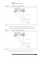
Step 6. Setup the instrument as shown in Figure 2-12.
Figure 2-12
Handler Interface Simulator Setup
3. Chapter Title
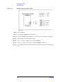
Step 5. Confirm the LEDs on the handler interface simulator as shown in Figure 2-14 on page 35 is
mounted. If all LEDs is not mounted, add LEDs(Agilent P/N 1990-0486).
4. Chapter Title
5. Chapter Title
Step 7. Set START/STOP, CH.RESET, KEYLOCK Switches as shown in Figure 2-13
Chapter 2
33
Performance Test
Function Test
Figure 2-13
Handler Interface Simulator Setting
Step 8. Turn on the 4288A.
Step 9. Press blue-[.]-[↑→]-[Enter] to reset the 4288A.
Step 10. Confirm EOM,INDEX and CH2 light. The location are shown in Figure 2-14 on page 35.
Step 11. Press blue-[-] to show the configuration menu.
Step 12. Choose Svc with [←↓] and [↑→] key, then Press [Enter].
Step 13. Choose HNDL with [←↓] and [↑→] key, then Press [Enter] to start the test.
Step 14. Confirm that the LEDs on the handler interface simulator light in the order shown in Figure
2-14.
34
Chapter 2
Figure 2-14
Order of LEDs lightning
1. Chapter Title
Performance Test
Function Test
2. Performance Test
3. Chapter Title
Step 15. Exit from the test mode by Pressing [Enter], then press [Enter] twice to exit the
configuration mode.
Step 16. Press the [Trig Mode] key several times until the W symbol is displayed above Man.
Step 17. Set the KEYLOCK switch on the handler interface simulator to ON.
Step 18. Confirm that the all keys on the 4288A front panel are locked out.
Step 19. Seth the KEYLOCK switch to OFF.
Step 20. Turn off the 4288A
Step 21. Disconnect the handler interface simulator from the 4288A.
4. Chapter Title
Step 22. Setup the equipment as shown in Figure 2-15.
5. Chapter Title
Chapter 2
35
Performance Test
Function Test
Figure 2-15
Scanner Interface Simulator Setup
Step 23. Turn on the 4288A.
Step 24. Set the jumper on the scanner interface simulator to 1 as shown in Figure 2-16.
Figure 2-16
Jumper Setting
Step 25. Press blue-[-] to show the configuration menu.
Step 26. Choose Svc with [←↓] and [↑→] key, then Press [Enter].
Step 27. Choose SCNR with [←↓] and [↑→] key, then Press [Enter] to start the test.
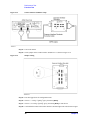
Step 28. Confirm that the LEDs on the scanner interface simulator light in the order shown in Figure
36
Chapter 2
2-17, in accordance with the 4288A display.
NOTE
Generally the CHn LED light, “CH 2n” is displayed on the 4288A display. However, “CH
0” is displayed when CH6 or CH7 LED light.
Figure 2-17
Scanner Interface Output Order
1. Chapter Title
Performance Test
Function Test
2. Performance Test
Step 29. If all tests work correctly, check pass into the function test record.
3. Chapter Title
4. Chapter Title
5. Chapter Title
Chapter 2
37
Performance Test
Calculation Sheet
Calculation Sheet
Performance Test
Frequency Accuracy Test
Frequency
Frequency Shift
1 kHz
0%
kHz
1 MHz
0%
MHz
(a − 1) × 106 Hz
−1 %
MHz
(a − 0.99) × 106 Hz
+1 %
MHz
(a − 1.01) × 106 Hz
+2 %
MHz
(a − 1.02) × 106 Hz
38
Counter Reading [a]
Test Result Equation
(a − 1) × 1000 Hz
Chapter 2
Signal Level Accuracy Test
1 kHz
0%
1000 mV
V
(a - 1) × 1000 mV
500 mV
V
(a - 0.5) × 1000 mV
300 mV
V
(a - 0.3) × 1000 mV
100 mV
V
(a - 0.1) × 1000 mV
1000 mV
V
(a - 1) × 1000 mV
500 mV
V
(a - 0.5) × 1000 mV
300 mV
V
(a - 0.3) × 1000 mV
100 mV
V
(a - 0.1) × 1000 mV
1000 mV
V
(a - 1) × 1000 mV
500 mV
V
(a - 0.5) × 1000 mV
300 mV
V
(a - 0.3) × 1000 mV
100 mV
V
(a - 0.1) × 1000 mV
1000 mV
V
(a - 1) × 1000 mV
500 mV
V
(a - 0.5) × 1000 mV
300 mV
V
(a - 0.3) × 1000 mV
100 mV
V
(a - 0.1) × 1000 mV
1000 mV
V
(a - 1) × 1000 mV
500 mV
V
(a - 0.5) × 1000 mV
300 mV
V
(a - 0.3) × 1000 mV
100 mV
V
(a - 0.1) × 1000 mV
1 MHz
0%
−1 %
+1 %
+2 %
Multimeter Reading
[a]
Test Result
Equation
4. Chapter Title
Signal Level
3. Chapter Title
Frequency Shift
2. Performance Test
Frequency
1. Chapter Title
Performance Test
Calculation Sheet
5. Chapter Title
Chapter 2
39
Performance Test
Calculation Sheet
Capacitance Measurement Accuracy Test
DUT
Frequency
Parameter
1 pF
1 MHz
Cp
Calibration Value [a]
Reference
Designation
pF
D
10 pF
1 MHz
Cp
CV2
pF
D
100 pF
1 kHz
Cp
Cp
pF
1 kHz
Cp
pF
Cp
pF
1 kHz
Cp
pF
1 kHz
Cp
nF
1 kHz
Cp
nF
1 kHz
Cp
D
40
CV15
CV16
μF
D
10 μF
CV13
CV14
D
1 μF
CV11
CV12
D
0.1 μF
CV9
CV10
D
0.01 μF
CV7
CV8
D
1 MHz
CV5
CV6
D
1000 pF
CV3
CV4
D
1 MHz
CV1
CV17
CV18
μF
CV19
CV20
Chapter 2
Cable Length:
DUT:
Range:
Meas. Time:
2m
1 pF
1 pF (Averaging: 1)
Long
Frequency
Frequency
Shift
Signal Level
Parameter
1 MHz
0%
1000 mV
Cp
4288A Reading [a]
Test Result
Equation
pF
Cp
pF
1000 mV
Cp
pF
1000 mV
Cp
pF
Frequency
Shift
Signal Level
Parameter
1 MHz
0%
1000 mV
Cp
4288A Reading [a]
Test Result
Equation
pF
Cp
pF
Cp
pF
1000 mV
Cp
D
a − CV3
a − CV4
D
+2 %
4. Chapter Title
1000 mV
a − CV3
a − CV4
D
+1 %
a − CV3
a − CV4
D
1000 mV
3. Chapter Title
2m
10 pF
10 pF (Averaging: 1)
Long
Frequency
−1 %
a − CV1
a − CV2
D
Cable Length:
DUT:
Range:
Meas. Time:
a − CV1
a − CV2
D
+2 %
a − CV1
a − CV2
D
+1 %
2. Performance Test
1000 mV
a − CV1
a − CV2
D
−1 %
1. Chapter Title
Performance Test
Calculation Sheet
pF
a − CV3
a − CV4
5. Chapter Title
Chapter 2
41
Performance Test
Calculation Sheet
Cable Length:
DUT:
Range:
Meas. Time:
2m
100 pF
100 pF (Averaging: 1)
Long
Frequency
Frequency
Shift
Signal Level
Parameter
1 kHz
0%
1000 mV
Cp
4288A Reading [a]
Test Result
Equation
pF
a − CV6
D
1 MHz
0%
1000 mV
Cp
pF
Cp
pF
1000 mV
Cp
pF
1000 mV
Cp
pF
1000 mV
Cp
pF
2m
100 pF
220 pF (Averaging: 1)
Long
Frequency
Frequency
Shift
Signal Level
Parameter
1 MHz
0%
1000 mV
Cp
4288A Reading [a]
Test Result
Equation
pF
1000 mV
Cp
pF
1000 mV
Cp
pF
1000 mV
Cp
D
42
a − CV7
a − CV8
D
+2 %
a − CV7
a − CV8
D
+1 %
a − CV7
a − CV8
D
−1 %
a − CV7
a − CV8
D
Cable Length:
DUT:
Range:
Meas. Time:
a − CV7
a − CV8
D
+2 %
a − CV7
a − CV8
D
+1 %
a − CV7
a − CV8
D
−1 %
a − CV7
a − CV8
D
100 mV
a − CV5
pF
a − CV7
a − CV8
Chapter 2
Cable Length:
DUT:
Range:
Meas. Time:
2m
100 pF
470 pF (Averaging: 1)
Long
Frequency
Frequency
Shift
Signal Level
Parameter
1 MHz
0%
1000 mV
Cp
4288A Reading [a]
Test Result
Equation
pF
Cp
pF
1000 mV
Cp
pF
1000 mV
Cp
pF
a − CV7
a − CV8
D
2m
100 pF
100 pF (Averaging: 1)
Short
Frequency
Frequency
Shift
Signal Level
Parameter
1 MHz
0%
1000 mV
Cp
D
4288A Reading [a]
3. Chapter Title
Cable Length:
DUT:
Range:
Meas. Time:
a − CV7
a − CV8
D
+2 %
a − CV7
a − CV8
D
+1 %
2. Performance Test
1000 mV
a − CV7
a − CV8
D
−1 %
1. Chapter Title
Performance Test
Calculation Sheet
Test Result
Equation
pF
a − CV7
a − CV8
4. Chapter Title
5. Chapter Title
Chapter 2
43
Performance Test
Calculation Sheet
Cable Length:
DUT:
Range:
Meas. Time:
2m
1000 pF
1 nF(Averaging: 1)
Long
Frequency
Frequency
Shift
Signal Level
Parameter
1 kHz
0%
1000 mV
Cp
4288A Reading [a]
Test Result
Equation
nF
D
1 MHz
0%
1000 mV
a / 1000− CV10
Cp
nF
1000 mV
Cp
nF
1000 mV
Cp
nF
1000 mV
Cp
nF
2m
0.01 μF
10 nF(Averaging: 1)
Long
Frequency
Frequency
Shift
Signal Level
Parameter
1 kHz
0%
1000 mV
Cp
4288A Reading [a]
Test Result
Equation
nF
2m
0.1 μF
100 nF(Averaging: 1)
Long
Frequency
Frequency
Shift
Signal Level
Parameter
1 kHz
0%
1000 mV
Cp
4288A Reading [a]
Test Result
Equation
nF
Cp
D
44
a − CV15
a − CV16
D
100 mV
a − CV13
a − CV14
D
Cable Length:
DUT:
Range:
Meas. Time:
a / 1000 − CV11
a / 1000 − CV12
D
Cable Length:
DUT:
Range:
Meas. Time:
a / 1000 − CV11
a / 1000 − CV12
D
+2 %
a / 1000 − CV11
a / 1000 − CV12
D
+1 %
a / 1000 − CV11
a / 1000 − CV12
D
−1 %
a / 1000 − CV9
nF
a − CV15
a − CV16
Chapter 2
Cable Length:
DUT:
Range:
Meas. Time:
2m
0.1 μF
220 nF(Averaging: 1)
Long
Frequency
Frequency
Shift
Signal Level
Parameter
1 kHz
0%
1000 mV
Cp
4288A Reading [a]
Test Result
Equation
nF
Frequency
Shift
Signal Level
Parameter
1 kHz
0%
1000 mV
Cp
4288A Reading [a]
Test Result
Equation
nF
a − CV15
a − CV16
D
3. Chapter Title
2m
0.1 μF
100 nF(Averaging: 1)
Short
Frequency
Frequency
Shift
Signal Level
Parameter
1 kHz
0%
1000 mV
Cp
4288A Reading [a]
Test Result
Equation
nF
a − CV15
a − CV16
D
2m
1 μF
1 μF (Averaging: 1)
Long
Frequency
Frequency
Shift
Signal Level
Parameter
1 kHz
0%
1000 mV
Cp
D
4288A Reading [a]
4. Chapter Title
Cable Length:
DUT:
Range:
Meas. Time:
2. Performance Test
2m
0.1 μF
470 nF(Averaging: 1)
Long
Frequency
Cable Length:
DUT:
Range:
Meas. Time:
a − CV15
a − CV16
D
Cable Length:
DUT:
Range:
Meas. Time:
1. Chapter Title
Performance Test
Calculation Sheet
Test Result
Equation
nF
a − CV17
a − CV18
5. Chapter Title
Chapter 2
45
Performance Test
Calculation Sheet
Cable Length:
DUT:
Range:
Meas. Time:
2m
10 μF
10 μF (Averaging: 1)
Long
Frequency
Frequency
Shift
Signal Level
Parameter
1 kHz
0%
1000 mV
Cp
4288A Reading [a]
Test Result
Equation
nF
a − CV20
D
Cable Length:
DUT:
Range:
Meas. Time:
1m
100 pF
100 pF (Averaging: 1)
Long
Frequency
Frequency
Shift
Signal Level
Parameter
1 MHz
0%
1000 mV
Cp
4288A Reading [a]
Test Result
Equation
pF
1000 mV
Cp
pF
1000 mV
Cp
pF
1000 mV
Cp
D
46
a − CV7
a − CV8
D
+2 %
a − CV7
a − CV8
D
+1 %
a − CV7
a − CV8
D
−1 %
a − CV19
pF
a − CV7
a − CV8
Chapter 2
Cable Length:
DUT:
Range:
Meas. Time:
0m
100 pF
100 pF (Averaging: 1)
Long
Frequency
Frequency
Shift
Signal Level
Parameter
1 MHz
0%
1000 mV
Cp
4288A Reading [a]
Test Result
Equation
pF
Cp
pF
1000 mV
Cp
pF
1000 mV
a − CV7
a − CV8
D
+2 %
a − CV7
a − CV8
D
+1 %
2. Performance Test
1000 mV
a − CV7
a − CV8
D
−1 %
Cp
1. Chapter Title
Performance Test
Calculation Sheet
pF
a − CV7
a − CV8
D
Signal Level Monitor Accuracy Test
Frequency
Shift
Multimeter
Reading [a]
Level Monitor
Reading [b]
Test Result
[1000×a−b]
Test Limit
1 kHz
0%
V
mV
mV
±4 mV
1 MHz
0%
V
mV
mV
±4 mV
−1 %
V
mV
mV
±4 mV
+1 %
V
mV
mV
±4 mV
+2 %
V
mV
mV
±4 mV
4. Chapter Title
Frequency
3. Chapter Title
Function Test
5. Chapter Title
Chapter 2
47
Performance Test
Test Record
Test Record
Agilent Technologies 4288A 1 kHz/1 MHz Capacitance Meter
Serial Number
Temperature:
Date:
Humidity:
Tested by:
Performance Test Record
Frequency Accuracy Test
Cable Length
2m
Frequency
Frequency Shift
Test Limit
1 kHz
0%
±0.20 Hz
Hz
±0.0100 Hz
1 MHz
0%
±200 Hz
Hz
±10.0 Hz
−1 %
±198 Hz
Hz
±9.9 Hz
+1 %
±202 Hz
Hz
±10.1 Hz
+2 %
±204 Hz
Hz
±10.2 Hz
48
Test Result
Measurement
Uncertainty
Chapter 2
Signal Level Accuracy Test
Cable Length:
2m
Test Limit
1 kHz
0%
1000 mV
±50 mV
mV
±0.26 mV
500 mV
±25 mV
mV
±0.14 mV
300 mV
±15 mV
mV
±0.096 mV
100 mV
±5.0 mV
mV
±0.025 mV
1000 mV
±50 mV
mV
±12 mV
500 mV
±25 mV
mV
±6.0 mV
300 mV
±15 mV
mV
±3.7 mV
100 mV
±5.0 mV
mV
±1.2 mV
1000 mV
±50 mV
mV
±12 mV
500 mV
±25 mV
mV
±6.0 mV
300 mV
±15 mV
mV
±3.7 mV
100 mV
±5.0 mV
mV
±1.2 mV
1000 mV
±50 mV
mV
±12 mV
500 mV
±25 mV
mV
±6.0 mV
300 mV
±15 mV
mV
±3.7 mV
100 mV
±5.0 mV
mV
±1.2 mV
1000 mV
±50 mV
mV
±12 mV
500 mV
±25 mV
mV
±6.0 mV
300 mV
±15 mV
mV
±3.7 mV
100 mV
±5.0 mV
mV
±1.2 mV
1 MHz
0%
−1 %
+1 %
+2 %
Test Result
Measurement
Uncertainty
4. Chapter Title
Signal Level
3. Chapter Title
Frequency
Shift
2. Performance Test
Frequency
1. Chapter Title
Performance Test
Test Record
5. Chapter Title
Chapter 2
49
Performance Test
Test Record
Capacitance Measurement Accuracy Test
Cable Length:
DUT:
Range:
Meas. Time:
2m
1 pF
1 pF (Averaging: 1)
Long
Frequency
Frequency
Shift
Signal
Level
Parameter
Test Limit
1 MHz
0%
1000 mV
Cp
±0.00085 pF
D
±0.00065
Cp
±0.00085 pF
D
±0.00065
Cp
±0.00085 pF
D
±0.00065
Cp
±0.00085 pF
D
±0.00065
−1 %
1000 mV
+1 %
1000 mV
+2 %
1000 mV
Cable Length:
DUT:
Range:
Meas. Time:
Frequency
Shift
Signal
Level
Parameter
Test Limit
1 MHz
0%
1000 mV
Cp
±0.0070 pF
D
±0.00050
Cp
±0.0070 pF
D
±0.00050
Cp
±0.0070 pF
D
±0.00050
Cp
±0.0070 pF
D
±0.00050
1000 mV
+1 %
1000 mV
+2 %
1000 mV
50
Measurement
Uncertainty
pF
±0.00024 pF
±0.00010
pF
±0.00024 pF
±0.00010
pF
±0.00024 pF
±0.00010
pF
±0.00024 pF
±0.00010
2m
10 pF
10 pF (Averaging: 1)
Long
Frequency
−1 %
Test Result
Test Result
Measurement
Uncertainty
pF
±0.0017 pF
±0.00008
pF
±0.0017 pF
±0.00008
pF
±0.0017 pF
±0.00008
pF
±0.0017 pF
±0.00008
Chapter 2
Cable Length:
DUT:
Range:
Meas. Time:
2m
100 pF
100 pF (Averaging: 1)
Long
Signal
Level
Parameter
Test Limit
1 kHz
0%
1000 mV
Cp
±0.085 pF
D
±0.00065
Cp
±0.070 pF
D
±0.00050
Cp
±0.205 pF
D
±0.00185
Cp
±0.070 pF
D
±0.00050
Cp
±0.070 pF
D
±0.00050
Cp
±0.070 pF
D
±0.00050
1 MHz
0%
1000 mV
100 mV
−1 %
1000 mV
+1 %
1000 mV
+2 %
1000 mV
Cable Length:
DUT:
Range:
Meas. Time:
Signal
Level
Parameter
Test Limit
1 MHz
0%
1000 mV
Cp
±0.088 pF
D
±0.00068
Cp
±0.088 pF
D
±0.00068
Cp
±0.088 pF
D
±0.00068
Cp
±0.088 pF
D
±0.00068
+1 %
+2 %
1000 mV
1000 mV
pF
±0.020 pF
±0.00006
pF
±0.020 pF
±0.00009
pF
±0.020 pF
±0.00009
pF
±0.020 pF
±0.00009
pF
±0.020 pF
±0.00009
pF
±0.020 pF
±0.00009
Test Result
Measurement
Uncertainty
pF
±0.020 pF
4. Chapter Title
Frequency
Shift
1000 mV
Measurement
Uncertainty
2m
100 pF
220 pF (Averaging: 1)
Long
Frequency
−1 %
Test Result
3. Chapter Title
Frequency
Shift
2. Performance Test
Frequency
1. Chapter Title
Performance Test
Test Record
±0.00009
pF
±0.020 pF
±0.00009
pF
±0.020 pF
±0.00009
pF
±0.020 pF
±0.00009
5. Chapter Title
Chapter 2
51
Performance Test
Test Record
Cable Length:
DUT:
Range:
Meas. Time:
2m
100 pF
470 pF (Averaging: 1)
Long
Frequency
Frequency
Shift
Signal
Level
Parameter
Test Limit
1 MHz
0%
1000 mV
Cp
±0.125 pF
D
±0.00105
Cp
±0.125 pF
D
±0.00105
Cp
±0.125 pF
D
±0.00105
Cp
±0.125 pF
D
±0.00105
−1 %
1000 mV
+1 %
1000 mV
+2 %
1000 mV
Cable Length:
DUT:
Range:
Meas. Time:
Measurement
Uncertainty
pF
±0.020 pF
±0.00009
pF
±0.020 pF
±0.00009
pF
±0.020 pF
±0.00009
pF
±0.020 pF
±0.00009
2m
100 pF
100 pF (Averaging: 1)
Short
Frequency
Frequency
Shift
Signal
Level
Parameter
Test Limit
1 MHz
0%
1000 mV
Cp
±0.085 pF
D
±0.00065
52
Test Result
Test Result
Measurement
Uncertainty
pF
±0.020 pF
±0.00009
Chapter 2
Cable Length:
DUT:
Range:
Meas. Time:
2m
1000 pF
1 nF(Averaging: 1)
Long
Signal
Level
Parameter
Test Limit
1 kHz
0%
1000 mV
Cp
±0.70 pF
D
±0.00050
Cp
±0.70 pF
D
±0.00050
Cp
±0.70 pF
D
±0.00050
Cp
±0.70 pF
D
±0.00050
Cp
±0.70 pF
D
±0.00050
1 MHz
0%
1000 mV
−1 %
1000 mV
+1 %
1000 mV
+2 %
1000 mV
Cable Length:
DUT:
Range:
Meas. Time:
Signal
Level
Parameter
Test Limit
1 kHz
0%
1000 mV
Cp
±0.0070 nF
D
±0.00050
±0.20 pF
±0.00007
pF
±0.21 pF
±0.00009
pF
±0.21 pF
±0.00009
pF
±0.21 pF
±0.00009
pF
±0.21 pF
±0.00009
Test Result
Measurement
Uncertainty
nF
±0.0018 nF
±0.00003
2m
0.1 μF
100 nF(Averaging: 1)
Long
Frequency
Shift
Signal
Level
Parameter
Test Limit
1 kHz
0%
1000 mV
Cp
±0.070 nF
D
±0.00050
Cp
±0.205 nF
D
±0.00185
Test Result
Measurement
Uncertainty
nF
±0.018 nF
±0.00003
nF
±0.018 nF
5. Chapter Title
Frequency
Chapter 2
pF
4. Chapter Title
Frequency
Shift
100 mV
Measurement
Uncertainty
2m
0.01 μF
10 nF(Averaging: 1)
Long
Frequency
Cable Length:
DUT:
Range:
Meas. Time:
Test Result
3. Chapter Title
Frequency
Shift
2. Performance Test
Frequency
1. Chapter Title
Performance Test
Test Record
±0.00003
53
Performance Test
Test Record
Cable Length:
DUT:
Range:
Meas. Time:
2m
0.1 μF
220 nF(Averaging: 1)
Long
Frequency
Frequency
Shift
Signal
Level
Parameter
Test Limit
1 kHz
0%
1000 mV
Cp
±0.088 nF
D
±0.00068
Cable Length:
DUT:
Range:
Meas. Time:
Frequency
Shift
Signal
Level
Parameter
Test Limit
1 kHz
0%
1000 mV
Cp
±0.125 nF
D
±0.00105
Frequency
Shift
Signal
Level
Parameter
Test Limit
1 kHz
0%
1000 mV
Cp
±0.085 nF
D
±0.00065
±0.018 nF
±0.00003
Test Result
Measurement
Uncertainty
nF
±0.018 nF
±0.00003
Test Result
Measurement
Uncertainty
nF
±0.005 nF
±0.00003
2m
1 μF
1 μF (Averaging: 1)
Long
Frequency
Frequency
Shift
Signal
Level
Parameter
Test Limit
1 kHz
0%
1000 mV
Cp
±0.00070 μF
D
±0.00050
54
nF
2m
0.1 μF
100 nF(Averaging: 1)
Short
Frequency
Cable Length:
DUT:
Range:
Meas. Time:
Measurement
Uncertainty
2m
0.1 μF
470 nF(Averaging: 1)
Long
Frequency
Cable Length:
DUT:
Range:
Meas. Time:
Test Result
Test Result
Measurement
Uncertainty
μF
±0.00018 μF
±0.00005
Chapter 2
Cable Length:
DUT:
Range:
Meas. Time:
2m
10 μF
10 μF (Averaging: 1)
Long
Frequency
Shift
Signal
Level
Parameter
Test Limit
1 kHz
0%
1000 mV
Cp
±0.0070 μF
D
±0.00050
Cable Length:
DUT:
Range:
Meas. Time:
Signal
Level
Parameter
Test Limit
1 MHz
0%
1000 mV
Cp
±0.070 pF
D
±0.00050
Cp
±0.070 pF
D
±0.00050
Cp
±0.070 pF
D
±0.00050
Cp
±0.070 pF
D
±0.00050
+1 %
+2 %
1000 mV
1000 mV
μF
±0.0020 μF
±0.00008
Test Result
Measurement
Uncertainty
pF
±0.020 pF
±0.00009
pF
3. Chapter Title
Frequency
Shift
1000 mV
Measurement
Uncertainty
1m
100 pF
100 pF (Averaging: 1)
Long
Frequency
−1 %
Test Result
2. Performance Test
Frequency
1. Chapter Title
Performance Test
Test Record
±0.020 pF
±0.00009
pF
±0.020 pF
±0.00009
pF
±0.020 pF
±0.00009
4. Chapter Title
5. Chapter Title
Chapter 2
55
Performance Test
Test Record
Cable Length:
DUT:
Range:
Meas. Time:
0m
100 pF
100 pF (Averaging: 1)
Long
Frequency
Frequency
Shift
Signal
Level
Parameter
Test Limit
1 MHz
0%
1000 mV
Cp
±0.070 pF
D
±0.00050
Cp
±0.070 pF
D
±0.00050
Cp
±0.070 pF
D
±0.00050
Cp
±0.070 pF
D
±0.00050
−1 %
1000 mV
+1 %
1000 mV
+2 %
1000 mV
56
Test Result
Measurement
Uncertainty
pF
±0.020 pF
±0.00009
pF
±0.020 pF
±0.00009
pF
±0.020 pF
±0.00009
pF
±0.020 pF
±0.00009
Chapter 2
Function Test Record
1. Chapter Title
Performance Test
Test Record
Signal Level Monitor Test
Pass
Fail
[ ]
[ ]
Pass
Fail
[ ]
[ ]
2. Performance Test
Handler Interface & Scanner Interface Test
3. Chapter Title
4. Chapter Title
5. Chapter Title
Chapter 2
57
Performance Test
Test Record
58
Chapter 2
1. Chapter Title
2. Chapter Title
3. Adjustment
4. Chapter Title
3
Adjustment
5. Chapter Title
This Chapter provides the adjustment procedures required to ensure that the 4288A
1kHz/1MHz Capacitance Meter is within its published specifications after it has been
repaired, or when it fails the performance tests..
59
Adjustment
Safety Considerations
Safety Considerations
This manual contains NOTEs, CAUTIONs, and WARNINGs that must be followed to
ensure the safety of the operator and to keep the instrument in a safe and serviceable
condition. The Adjustment must be performed by qualified service personnel.
WARNING
Any interruption of the protective ground conductor (inside or outside the meter) or
disconnection of the protective ground terminal can make the instrument dangerous.
Intentional interruption of the protective ground system for any reason is prohibited.
Required Controller
The following controller system is required to run the adjustment program.
Windows PC
PC-AT Compatible, RAM:≥64MBytes, CPU Pentium 200 MHz or
faster
OS
Microsoft® Windows 2000®
Software
Agilent VEE (5.0 or 6.2)
GPIB Card
Agilent 82350A, 82341C/D
Required Equipment
Table 1-1 on page 14 lists the equipment required to perform the Adjustment procedures
described in this chapter. Use only calibrated test equipment when adjusting the 4288A.
Warm-up for Adjustment
Warm-up the 4288A for at least 30 minute before performing any of the following
Adjustment procedures to ensure procedures to ensure proper results and correct
instrument operation.
60
Chapter 3
Order of Adjustment
1. Chapter Title
Adjustment
Order of Adjustment
When performing more than one adjustment, perform them in the order they appear in this
chapter. The procedures are presented in the following order.
2. Chapter Title
3. Adjustment
4. Chapter Title
5. Chapter Title
Chapter 3
61
Adjustment
Preparation for using the Adjustment Program
Preparation for using the Adjustment Program
To use the Adjustment Program, some preparation is required. This section describes its
procedure.
Installing an GPIB Card (82340, 82341 or 82350)
Install an GPIB Card into your computer (see the GPIB Card manual). The select code of
the GPIB Card should be set to “7”.
Installing Agilent VEE for Personal Computer
Install the Agilent VEE into your computer (see the Agilent VEE for Windows®).
Installing Adjustment Program into Your PC
1. Make a copy of the 4288Aadjustment program named ADJ4288A.EXE in a directory
of your harddisk drive.
2. Double-click the filename on the Windows’Explorer to start extracting the
self-extracting archive.
3. You will be prompted to enter directory name for installing the program files. Input the
destination directory, then Click Unzip. The default is C:\ADJ4288A.
4. Confirm the message that you successfully extract the files and click OK and Close.
Equipment Setup
Performing adjustments requires the system described in this section. The Hardware Setup
is shown in Figure 3-1.
Figure 3-1
Adjustment Hardware Setup
62
Chapter 3
Running the Adjustment Program
1. Chapter Title
Adjustment
Running the Adjustment Program
1. Start the Agilent VEE.
2. Load the adjustment program file into the Agilent VEE as follows.
a. Pull down the File menu from the Agilent VEE window and select Open.
3. You may be asked to add drivers for the equipment during the program loading. Click
OK and enter the GPIB address for each equipment. Enter 0 as the address for the
equipment which are not used for the adjustment. (Refer to Table 3-1)
Table 3-1
Device Name and GPIB Address Example
Device Name
Equipment
GPIB Address
4288A
4288A
717
3458A
3458A
722
5. The program ask to input the home directory and the GPIB addresses of the equipment
as shown in Figure 3-2. The home directory is the directory where ADJ4288A.VEE is
stored.
Figure 3-2
3. Adjustment
4. Click START button on the VEE Screen.
2. Chapter Title
b. Select the file ADJ4288A.VEE in the target directory at Step 3 in “Installing
Adjustment Program into Your PC” on page 62, then click Open.
Environment setting window
4. Chapter Title
Chapter 3
5. Chapter Title
6. The program ask to input calibration data of the 100 pF and the 0.1 μF standard
capacitor as shown in Figure 3-3.
63
Adjustment
Running the Adjustment Program
Figure 3-3
Calibrating data input window
7. The Serial Number input window as
Figure 3-4
Serial Number input window
8. The main menu widow appears as Figure 3-5. Choose the proper menu. The description
of each menu is as follows.
•
All Adjustment
Perform the all adjustments.
•
Partial Adjustment
Perform some continued adjustments.
•
Spot Adjustment
Perform an adjustment.
•
Input SN
Input SN when adjusting another 4288A.
•
Program END
Stop the adjustment program.
64
Chapter 3
Figure 3-5
Main menu window
1. Chapter Title
Adjustment
Running the Adjustment Program
2. Chapter Title
3. Adjustment
4. Chapter Title
5. Chapter Title
Chapter 3
65
Adjustment
Correction Constant Initialization
Correction Constant Initialization
The purpose of this procedure is to initialize correction constants and write the default data
to the EEPROM.
Required Equipment
None
Procedure
Step 1. Run the adjustment program.
Step 2. Choose InitCal.
Step 3. Confirm nothing is connected to the 4288A UNKNOWN terminal.
Step 4. Follow the adjustment program instruction to initialize the correction constants.
66
Chapter 3
Voltage Monitor Correction Constants
1. Chapter Title
Adjustment
Voltage Monitor Correction Constants
This adjustment calibrate the Voltage Monitor’s absolute measurement accuracy. The
calibration data in the form of correction constants is stored in the EEPROM.
Required Equipment
Recommended Model
Multimeter
3458A
Interface Box
p/n 04284-65007
BNC(m)-BNC(m) Cable, 61 cm
p/n 8120-1839
BNC(f)-Dual Banana Plug
p/n 1251-2277
2. Chapter Title
Description
Procedure
Step 1. Run the adjustment program.
3. Adjustment
Step 2. Choose AdjVMon.
Step 3. Connect the equipment as shown in Figure 3-6.
Figure 3-6
Voltage Monitor Adjustment Setup
4. Chapter Title
5. Chapter Title
Step 4. Follow the adjustment program instruction to update the correction constants.
Chapter 3
67
Adjustment
Source DC offset Correction Constants
Source DC offset Correction Constants
This adjustment calibrate DAC value to prevent DC voltage from outputting from Hcur
connector. The calibration data in the form of correction constants is stored in the
EEPROM.
Required Equipment
Description
Recommended Model
Open Termination
42090A
Procedure
Step 1. Run the adjustment program.
Step 2. Choose AdjDCoffs.
Step 3. Connect the open termination to the 4288A UNKNOWN terminal as shown in Figure 3-7.
Figure 3-7
Source DC Offset Correction Constants Setup
Step 4. Follow the adjustment program instruction to update the correction constants.
68
Chapter 3
Source Level Correction Constants
1. Chapter Title
Adjustment
Source Level Correction Constants
This adjustment calibrate the source level. The calibration data in the form of correction
constants is stored in the EEPROM.
Required Equipment
Recommended Model
Open Termination
42090A
2. Chapter Title
Description
Procedure
Step 1. Run the adjustment program.
Step 2. Choose AdjsrcLvl.
Step 3. Connect the open termination to the 4288A UNKNOWN terminal as shown in Figure 3-8.
Source Level Correction Constants Setup
3. Adjustment
Figure 3-8
4. Chapter Title
Step 4. Follow the adjustment program instruction to update the correction constants.
5. Chapter Title
Chapter 3
69
Adjustment
Current Sense Offset Correction Constants
Current Sense Offset Correction Constants
This correction constants calibrate the DAC in the Lc amp to cancel the DC voltage at the
input to the ADC. The calibration data in the form of correction constants is stored in the
EEPROM.
Required Equipment
Description
Recommended Model
Open Termination
42090A
Procedure
Step 1. Run the adjustment program.
Step 2. Choose AdjISense.
Step 3. Connect the open termination to the 4288A UNKNOWN terminal as shown in Figure 3-9.
Figure 3-9
Current Sense Offset Correction Constants Setup
Step 4. Follow the adjustment program instruction to update the correction constants.
70
Chapter 3
Modem Offset Correction Constants
1. Chapter Title
Adjustment
Modem Offset Correction Constants
The correction constants calibrate the DAC in the MODEM to cancel the output current of
the MODEM on the OPEN measurement. The calibration data in the form of correction
constants is stored in the EEPROM.
Required Equipment
Recommended Model
Open Termination
42090A
2. Chapter Title
Description
Procedure
Step 1. Run the adjustment program.
Step 2. Choose AdjModem.
Step 3. Connect the open termination to the 4288A UNKNOWN terminal as shown in Figure 3-10.
3. Adjustment
Figure 3-10
Modem Offset Correction Constants Setup
4. Chapter Title
Step 4. Follow the adjustment program instruction to update the correction constants.
5. Chapter Title
Chapter 3
71
Adjustment
Linearity Correction Constants
Linearity Correction Constants
The adjustment calibrate the linearity of the voltage meter and the current meter. The
calibration data in the form of correction constants is stored in the EEPROM.
Required Equipment
Description
Recommended Model
Open Termination
42090A
Procedure
Step 1. Run the adjustment program.
Step 2. Choose AdjLinear.
Step 3. Connect the open termination to the 4288A UNKNOWN terminal as shown in Figure 3-11.
Figure 3-11
Linearity Correction Constants Setup
Step 4. Follow the adjustment program instruction to update the correction constants.
72
Chapter 3
VRD Gain Correction Constants
1. Chapter Title
Adjustment
VRD Gain Correction Constants
The adjustment calibrate the amplifiers’ gain and phase shift. The calibration data in the
form of correction constants is stored in the EEPROM.
Required Equipment
Recommended Model
Open Termination
42090A
2. Chapter Title
Description
Procedure
Step 1. Run the adjustment program.
Step 2. Choose AdjVRDGain.
Step 3. Connect the open termination to the 4288A UNKNOWN terminal as shown in Figure 3-12.
VRD Gain Correction Constants Setup
3. Adjustment
Figure 3-12
4. Chapter Title
Step 4. Follow the adjustment program instruction to update the correction constants.
5. Chapter Title
Chapter 3
73
Adjustment
TRD Range Resistors Correction Constants
TRD Range Resistors Correction Constants
The adjustment calibrate the resistance ratio between the neighbor range resistor. The
calibration data in the form of correction constants is stored in the EEPROM.
Required Equipment
Description
Recommended Model
Open Termination
42090A
Procedure
Step 1. Run the adjustment program.
Step 2. Choose AdjTRDRr.
Step 3. Connect the open termination to the 4288A UNKNOWN terminal as shown in Figure 3-13.
Figure 3-13
TRD Range Resistors Correction Constants Setup
Step 4. Follow the adjustment program instruction to update the correction constants.
74
Chapter 3
Impedance Correction Constants
1. Chapter Title
Adjustment
Impedance Correction Constants
The adjustment calibrate the capacitance measurement accuracy to measure the standard
capacitor as a reference. The calibration data in the form of correction constants is stored in
the EEPROM.
Required Equipment
Recommended Model
Standard Capacitor Set
16380A
Standard Capacitor Set
16380C #001
Test Leads, 1 m
16048A
Test Leads, 2 m
16048D
2. Chapter Title
Description
Procedure
3. Adjustment
Step 1. Run the adjustment program.
Step 2. Choose AdjImp.
Step 3. Connect the equipment to the 4288A UNKNOWN terminal as shown in Figure 3-14.
Figure 3-14
Impedance Correction Constants Setup 1
4. Chapter Title
5. Chapter Title
Step 4. Follow the adjustment program instruction to update the correction constants.
Step 5. Connect the equipment to the 4288A UNKNOWN terminal as shown in Figure 3-15.
Chapter 3
75
Adjustment
Impedance Correction Constants
Figure 3-15
Impedance Correction Constants Setup 2
Step 6. Follow the adjustment program instruction to update the correction constants.
Step 7. Connect the equipment to the 4288A UNKNOWN terminal as shown in Figure 3-16.
Figure 3-16
Impedance Correction Constants Setup 3
Step 8. Follow the adjustment program instruction to update the correction constants.
76
Chapter 3
After Adjustment
1. Chapter Title
Adjustment
After Adjustment
The purpose of this procedure is to write a back-up date in the EEPROM.
Required Equipment
Nothing
2. Chapter Title
Procedure
Step 1. Run the adjustment program.
Step 2. Choose AfterAdj.
Step 3. Follow the adjustment program instruction to update the correction constants.
3. Adjustment
4. Chapter Title
5. Chapter Title
Chapter 3
77
Adjustment
After Adjustment
78
Chapter 3
1. Chapter Title
2. Chapter Title
3. Chapter Title
4. Troubleshooting
4
Troubleshooting
5. Chapter Title
This chapter describes troubleshooting flow and provides the procedure to determine
which group or assembly is faulty and should be checked.
79
Troubleshooting
Introduction
Introduction
Safety
Read the safety summary at the front of this manual before servicing the instrument.
WARNING
The servicing procedure described here are performed when power is supplied to the
instrument and its protective covers are removed. This type of servicing must be
performed only by service trained personnel who are aware of the hazards involved
(for example, fire and electrical shock). When servicing can be performed without
power applied to the instrument, remove power from the instrument. Before any
repair is completed, ensure that all safety features and functioning, and that all
necessary parts are properly connected to the protective grounding system.
ESD Precautions
When using any of the procedures in this chapter, you should use proper ESD precautions.
As a minimum you should place the instrument on a properly grounded ESD mat and wear
a properly grounded ESD wrist strap.
Required Equipment
The required equipment for troubleshooting is list on Table 1-1 on page 14.
80
Chapter 4
Trouble Isolation
1. Chapter Title
Troubleshooting
Trouble Isolation
Trouble Isolation Flowchart
Figure 4-1 shows the trouble isolation flowchart to isolate a defect assembly. Follow the
flowchart.for trouble isolation.
2. Chapter Title
Figure 4-1
Trouble Isolation Flowchart
3. Chapter Title
4. Troubleshooting
5. Chapter Title
Chapter 4
81
Troubleshooting
Trouble Isolation
Check 1: Power on self-test
Step 1. Turn off the 4288A, then turn on while watching the LCD.
Step 2. Check for a beep sound for a moment and if you see anything is displayed on the LCD.
Step 3. If nothing is shown in the LCD, proceed to “Check 2: Power Supply Check.”
Step 4. If an error message is displayed on the LCD, the power supply works properly. Proceed to
“Check 6: Digital Trouble Isolation.”
Step 5. If no error message is displayed on the LCD, the power supply and the digital control
circuit works properly. Proceed to “Check 5: External Test.”
Check 2: Power Supply Check
Step 1. Remove the cover as described in “Cover Removal” on page 114.
Step 2. Turn on the 4288A.
Step 3. Check the fuse in the AC inlet on the rear panel. If the fuse is defect, replace the fuse.
Step 4. Check the voltage between ground and each test pin with the multimeter. If the voltages are
between the test limit as shown in Table 4-1, proceed to Table , “Check 3: Fan Check.” If
all the voltages are not between the limit, the power supply or the Main Board.
82
Chapter 4
Test Point
Table 4-1
Power Supply Check Limit
2. Chapter Title
Figure 4-2
1. Chapter Title
Troubleshooting
Trouble Isolation
Test Limit
Original Voltage
from Power Supply
TP65
3.3 V ± 0.16 V
5V
TP66
5 V ± 0.25 V
12 V
TP67
10.5 V ± 0.5 V
TP68
−5 V ± 0.25 V
TP69
−10.5 V ± 0.5 V
TP70
Ground
Ground
TP71
5 V ± 0.25V
5V
3. Chapter Title
Cable Color
−12 V
4. Troubleshooting
Check 3: Fan Check
Step 1. Turn on the 4288A.
Step 2. Confirm that the fan is rotating. If the fan works properly, proceed to “Check 4: LCD
backlight.” If the fan is not rotating, replace the fan.
5. Chapter Title
Check 4: LCD backlight
Step 1. Turn on the 4288A.
Step 2. Remove the cable connected to LCD backlight from the keyboard.
Chapter 4
83
Troubleshooting
Trouble Isolation
Step 3. Measure the voltage between the connector electrodes in the keyboard. If the voltage is
between 5 V ± 0.5 V, replace the LCD. If not, replace the A1 main board, the keyboard or
the flat cable connecting between the A1 board and the keyboard.
Check 5: External Test
Step 1. Turn on the 4288A.
Step 2. Execute the external test as described in “External test” on page 86. If the test fails, replace
the A1 main board.
Check 6: Digital Trouble Isolation
Step 1. If the error number is 17, replace the fan.
Step 2. If the error number is 19 or 20, turn off the 4288A then turn on again. If the same error
number is displayed again, replace the main board.
Step 3. If another error number is displayed, replace the main board.
84
Chapter 4
Service Functions
1. Chapter Title
Troubleshooting
Service Functions
The service functions are used to test, verify, control, and troubleshoot
Firmware Revision Confirmation
The firmware revision can be confirmed with either of the following procedure.
Turn the 4288A off, then turn it on again. (Immediately after turning on, the firmware
revision and the serial number appear in the LCD.)
•
Press blue-[-] to show the configuration menu as Figure 4-3. Use the [←↓] or [↑→] to
blink Rev, then press the [Enter] key.
2. Chapter Title
Figure 4-3
•
Configuration menu
3. Chapter Title
Internal Test
The 4288A provides a self-test function. The self-test performs brief check of the operation
of digital parts including memory.
Step 1. Press blue-[-] to show the configuration menu as Figure 4-4.
Figure 4-4
Configuration menu
4. Troubleshooting
Step 2. Use the [↑→] key to blink Test and then press [Enter]. The test menu appears as shown in
Figure 4-5.
5. Chapter Title
Chapter 4
85
Troubleshooting
Service Functions
Figure 4-5
Test menu
Step 3. Use the [↑→] key to blink Internal and then press [Enter]. The “SELF TESTING”
message appears and the self-test is executed.
Step 4. When the test is completed, “SELF TEST: PASS” is displayed for approximately 1 second
(if an error occurs, its error number is displayed. For details on displayed error number,
refer to Table 4-2) and then the menu in Step 1 appears,. Check that Exit is blinking (if
not, operate keys to blink Exit) and then press the [Enter] key to exit from the menu.
Table 4-2
Self-Test Items
Test item
Test description
Error code
RAM
Verifies that the RAM data bus is connected correctly
and there is no faulty memory cell.
1
Boot ROM
Verifies that the check sum of Boot ROM is correct.
2
Flash ROM
Verifies that the check sum of Flash ROM is correct.
4
Calibration
data
Verifies that the check sum of the adjustment data in the
EEPROM is correct.
8
User
correction
data
Verifies that the checksum of the OPEN/SHORT/LOAD
correction data in the EEPROM is correct. Even if the
test fails, the correction data is not initialized.
16
A/D
converter
Verifies that the A/D converter operates normally.
32
Backup
RAM
Verifies that the instrument setting value in the backup
memory(RAM) is correct. Even if the test fails, the
instrument setting value is not initialized.
64
External test
The external test performs a simple operational testing on the analog circuitry using the
internal calibration resistors.
Procedure from the front panel
Step 1. Press the blue-[-] key. The configuration menu screen as shown in Figure 4-6 appears.
86
Chapter 4
Figure 4-6
The configuration menu
Figure 4-7
Test menu screen
Figure 4-8
3. Chapter Title
Step 3. Use the [↑→] and other necessary keys to blink External and press the [Enter] key. The
screen as shown in Figure 4-8 appears.
2. Chapter Title
Step 2. Use the [↑→ ] and other necessary keys to blink Test and press the [Enter] key. Test menu
screen as shown in Figure 4-7 appears.
1. Chapter Title
Troubleshooting
Service Functions
External test execution wait screen
4. Troubleshooting
Step 4. As shown in Figure 4-9, connect the 42090A to the UNKNOWN terminal of the 4288A (or
directly connect between LCUR and LPOT and between HCUR and HPOT with BNC cables).
5. Chapter Title
Chapter 4
87
Troubleshooting
Service Functions
Figure 4-9
Preparation for external test
Step 5. Use the [↑→] and other necessary keys to blink Yes and press the [Enter]. The external test
is performed in the order of test number. When the test completes, test result (PASS or
FAIL) is displayed to the right of EXTERNAL TEST: as shown in Figure 4-10 and the test
menu is brought back. When the test result is FAIL, failed test numbers and setting
numbers are additionally displayed (see Table 4-3 and Table 4-4). Replace the A1 main
board if this test fails.
Figure 4-10
Test result display screen (when setup 1 of measurement part test failed)
Table 4-3
External test items
Test number
Test item
Description
1
Entire analog circuitry
Check the 4288A which setting is after reset by “*RST” command.
2
Signal part (signal level)
Check set the signal level properly.
3
Signal part (frequency)
Check set the frequency properly.
4
Measurement part
Check set the measurement range properly.
88
Chapter 4
Table 4-4
External Test Setting
Frequency
Shift
Signal
Level
Range
Calibration
Resistor
Service
Mode
1
1
1 kHz
0%
1000 mV
100 pF
100 kΩ
OFF
2
1
1 kHz
0%
1000 mV
100 nF
1 kΩ
OFF
2
1 kHz
0%
500 mV
100 nF
1 kΩ
OFF
3
1 kHz
0%
100 mV
100 nF
1 kΩ
OFF
4
1 MHz
0%
1000 mV
100 pF
1 kΩ
OFF
5
1 MHz
0%
500 mV
100 pF
1 kΩ
OFF
6
1 MHz
0%
100 mV
100 pF
1 kΩ
OFF
1
1 kHz
0%
1000 mV
100 nF
1 kΩ
OFF
2
1 MHz
0%
1000 mV
100 pF
1 kΩ
OFF
3
1 MHz
+1 %
1000 mV
100 pF
1 kΩ
OFF
4
1 MHz
−1 %
1000 mV
100 pF
1 kΩ
OFF
5
1 MHz
+2 %
1000 mV
100 pF
1 kΩ
OFF
1
1 kHz
0%
1000 mV
1 nF
100 kΩ
OFF
2
1 kHz
0%
1000 mV
10 nF
10 kΩ
OFF
3
1 kHz
0%
1000 mV
100 nF
1 kΩ
OFF
4
1 kHz
0%
1000 mV
1 μF
100 Ω
OFF
5
1 kHz
0%
1000 mV
10 μF
100 Ω
OFF
6
1 MHz
0%
1000 mV
10 pF
100 kΩ
OFF
7
1 MHz
0%
1000 mV
100 pF
100 kΩ
OFF
8
1 MHz
0%
1000 mV
1 nF
100 kΩ
OFF
9
1 kHz
0%
1000 mV
100 nF
1 kΩ
ON
10
1 kHz
0%
1000 mV
100 nF
1 kΩ
OFF
3
4
4. Troubleshooting
Frequency
3. Chapter Title
Setting
Number
2. Chapter Title
Test
Number
1. Chapter Title
Troubleshooting
Service Functions
5. Chapter Title
Chapter 4
89
Troubleshooting
Service Functions
Procedure with GPIB command
The external test can be executed by sending the GPIB command “:STSTEM:TEST?”
The following the command reference.
Syntax
:SYSTEM:TEST?
Description
Executing this command perform the external test for the 4288A. To perform the external
test, you need to connect the equipment as shown in Figure 4-9.
Query response
{numeric 1},{numeric 2},{numeric 3},{numeric 4},{numeric 5}<newline><^END>
NOTE
“SYSTEM:TEST?” returns “0,0,0,0,0<newline>” when the external test passes.
NOTE
{numeric 1}:
Test number in Table 4-4
{numeric 2}:
Setting number in Table 4-4
{numeric 3}:
Failed measurement parameter 1:Impedance 2:V monitor 3:I monitor
{numeric 4}:
The expected value of the failed measurement parameter
{numeric 5}:
The measurement value of the failed measurement parameter. The
return value −1 means that the overload is detected.
The external test fails when the measurement value is out of the following test limit
Parameter
Test limit
Impedance
Expected Value ±5 %
V monitor
Expected Value ±20 %
I monitor
Expected Value ±20 %
90
Chapter 4
Power On Self-test
This test is executed when the 4288A is turned on. This test performs the following brief
checks of the operation of the including memory. This test is executed at power-on.
•
1. Chapter Title
Troubleshooting
Service Functions
RAM test failed
The RAM data bus or the address bus in NOT connected correctly. Replace A1 board.
•
Boot ROM test failed
•
Flash ROM test failed
The Flash ROM check sum is invalid. Install firmware to the Flash ROM. If the 4288A
still fails, replace the A1 board.
•
2. Chapter Title
The Boot ROM check sum is invalid. If only the Boot ROM is failed, replace the A1
Board.
EEPROM test failed
Read/Writing EEPROM is not performing correctly. If only the EEPROM test failed,
replace A1 board.
•
A1 board test failed
The A/D converter is not working properly. Replace the A1 board.
Calibration memory lost
The Factory Calibration Data in the EEPROM has been lost. Perform the adjustment.
•
User data lost
The User Correction Data in the EEPROM has been lost. The correction data is
initialized to the factory setting.
•
3. Chapter Title
•
Previous setting lost
The instrument setting values in the backup memory have been lost. These value is
initialized to the factory setting. Possible cause include a lapse of 72 hours after
power-off.
This test verifies that the front panel keys work correctly.
Step 1. Press the [Config]([Blue] - [−]) key. The configuration menu screen as shown in Figure 4-6
appears.
Figure 4-11
4. Troubleshooting
Front Panel Key Test
The configuration menu
5. Chapter Title
Chapter 4
91
Troubleshooting
Service Functions
Step 2. Use the [↑→ ] and other necessary keys to blink “Key” and press the [Enter] key. Test
menu screen as shown in Figure 4-7 appears.
Figure 4-12
Service function menu screen
Step 3. Press a key that you test. The name of the pressed key is displayed next to “KEY TEST:“ in
the upper line of the display. Figure 4-13 shows an example when Trig key is pressed.
Figure 4-13
Front Panel Key Test screen
Step 4. If you want to finish the test, press [Enter] key twice.
Interface Test
Verify the handler interface and the scanner interface function with the Handler & Scanner
Interface Tester(04288-65001). For detail, refer to “Handler Interface and Scanner
Interface Test” on page 30.
Handler Interface Test
Verify the handler interface with the Handler Simulator(04288-65001). For detail, refer to
“Handler Interface and Scanner Interface Test” on page 30.
Scanner Interface Test
Verify the handler interface with the Scanner Simulator(04278-65301). For detail, refer to
“Handler Interface and Scanner Interface Test” on page 30.
Memory Test
Verify the Boot ROM, the Flash ROM and the RAM.
Step 1. Press the [Config]([Blue] - [−]) key. The configuration menu screen as shown in Figure 4-6
appears.
92
Chapter 4
Figure 4-14
The configuration menu
2. Chapter Title
Step 2. Use the [↑→ ] and other necessary keys to blink “MEM” and press the [Enter] key. Test
menu screen as shown in Figure 4-7 appears.
Figure 4-15
1. Chapter Title
Troubleshooting
Service Functions
Service function menu screen
3. Chapter Title
Step 3. “PASS” or “FAIL” is displayed next to “BOOT TEST:”, “FLASH TEST:” and “RAM
TEST:” in the upper line of the display.
4. Troubleshooting
5. Chapter Title
Chapter 4
93
Troubleshooting
Service Functions
94
Chapter 4
1. Chapter Title
2. Chapter Title
3. Chapter Title
4. Chapter Title
5
Theory of Operation
95
5. Theory of Operation
This chapter describes the general overall operation of the 4288A and the operation of each
assembly.
Theory of Operation
Overall Operation
Overall Operation
Overall Operation
The 4288A measures the impedance of the Device Under Test (DUT) by measuring vector
voltage to current ratio. A vector is a value which consists of a magnitude and a phase. The
impedance of the DUT is determined by the vector ratio bet ween the voltage across the
DUT and the current passing through it. The 4288A essentially consists of a signal source,
a vector voltmeter, and a vector current meter.
Figure 5-1
Measurement Principle
In Figure 5-1, a DUT connected in series, a DUT connected in series with a test voltage
source (including an output resistance), voltmeter V, and ammeter, A. If the ammeter
measures i x ampere when the source voltage is e x , the DUT’s impedance Z x is expressed
by the following equation.
e
Z x = ----x
ix
Function Groups
The 4288A consists of three main functional groups: a power supply, a digital control and
an analog circuit. The analog circuit contains a source, a transducer and vector ratio
detector. A power supply function is consist of pre-regulator. A digital control function
consists of several assemblies and a part of the A1 Main Board. The analog circuit are
mounted on the A1 Main board.
96
Chapter 5
Power Supply Circuit
The power supply functional group consists of the pre-regulator. It supplies power to the
other assemblies in the 4288A.
1. Chapter Title
Theory of Operation
Overall Operation
Digital Control
The digital control block group consists of the keyboard, the LCD and a part of the A1
Main board. This function control the 4288A.
The 4288A analog circuit consists of three main functions, the source, the transducer and
the vector ratio detector.
The source function is mounted on the A1 Main Board. These source generates all analog
signals in the 4288A, a phase locked test signal to the device under test.
2. Chapter Title
Analog Circuit
The transducer function is mounted on the A1 main board. This function balances the
range resistor current with the DUT current to maintain the zero potential at the low
terminal(Lp) and transforms the DUT impedance, or admittance, into two AC signals
The vector ratio detector (VRD) functions is mounted on the A1 Main board. The vector
ratio detector converts the two AC signals from the transducer function into digital data.
3. Chapter Title
4. Chapter Title
97
5. Theory of Operation
Chapter 5
Theory of Operation
Power Supply Operation
Power Supply Operation
The power supply functional group consists of the following assemblies.
Line Power Module
The line power module includes the main fuse. The main fuse, which protects the input
side of the pre-regulator from drawing too much line current, is also accessible at thee rear
panel. See Appendix B, “Power Requirement,” on page 127 for the fuse replacement and
other power considerations.
Pre-regulator
The pre-regulator contains a rectifier and a switching regulator, converts the line voltage to
+5 V and ±12 V.
98
Chapter 5
Digital Control Operation
1. Chapter Title
Theory of Operation
Digital Control Operation
The digital control functional group consists of the following assemblies:
•
A part of the A1 main board
•
Front keyboard
•
LCD
2. Chapter Title
These assemblies combine to provide digital control for the 4288A. They provide math
processing functions, as well as communications between the 4288A and an external
controller and/or peripherals.
Figure 5-2
Digital control Group Simplified Block Diagram
3. Chapter Title
4. Chapter Title
The digital control section in the A1 main board consists of the following circuits and
Chapter 5
99
5. Theory of Operation
A1 Main Board
Theory of Operation
Digital Control Operation
parts.
CPU
central processing unit that controls the analyzer.
Memory storages
consists of the boot ROMs, Flash memory, EEPROM,
Backup SRAM.
Analog Interface
interfaces between the CPU and analog function.
Keyboard & LCD Control
controls the front-panel keyboard
Handler interface
control the external handler.
Scanner interface
control the scanner
GPIB Control
communicates with the external GPIB devices through
the GPIB connector.
Front Keyboard
The front keyboard assembly detects your inputs form the front panel of the 4288A, and
transmits them to the keyboard controller on the keyboard control in the A1 main board.
LCD
The LCD is receives a high voltage from the Inverter as backlight power and the digital
horizontal and the vertical signals from the GSP.
100
Chapter 5
Analog Circuit Operation
1. Chapter Title
Theory of Operation
Analog Circuit Operation
Figure 5-3 is the analog circuit block diagram. The analog circuit consists of the following
three functions.
Source
•
Transducer
•
Vector Ratio Detector (VRD)
2. Chapter Title
Figure 5-3
•
Analog Circuit Block Diagram
3. Chapter Title
4. Chapter Title
101
5. Theory of Operation
Chapter 5
Theory of Operation
Analog Circuit Operation
Source Theory
The source group generates all analog signals in the 4288A, a phase-locked test signal to
the device under test, the reference signals for the transducer group and the vector ratio
detector.
Figure 5-4
Source Function Simplified Block Diagram
The all analog signals derived from the PLL. The reference signals generated by the crystal
oscillator is transferred to the PLL. The 4288A shift the test signal frequency by changing
the dividing ratio in the PLL. The output signal of PLL is transferred to the signal
generator.
The signal from the PLL is converted to the simulated sinusoidal wave and transfer it to the
low-pass filter. The signal level is set by the DA converter.
The Hc Amp. produce signal voltage up to 1 V, and current up to 125 mA. The output
resistor is selected in accordance with the magnitude of the DUT impedance.
102
Chapter 5
Transducer Theory
The transducer group balances the range resistor current with the DUT current to maintain
a zero potential at the low terminal(Lp) and transforms the DUT impedance into two AC
signals.
1. Chapter Title
Theory of Operation
Analog Circuit Operation
The transducer consists of the following assemblies:
Lp Amp.
•
Hp Amp.
•
Lc Amp. and Range Resistor
•
IV Converter
•
MODEM
2. Chapter Title
Figure 5-5
•
Transducer Block Diagram
3. Chapter Title
4. Chapter Title
Lp Amp.
The Lp Amp. amplify the input signal from Lp terminal to keep the very high gain.
Hp Amp.
Lc Amp. & Range Resistor
The Lc Amp. detect the current flowing through the range resistor with the differential
Chapter 5
103
5. Theory of Operation
The Hp Amp. detect the voltage across the DUT by measuring the voltage between the
LPOT Terminal and the HPOT terminal.
Theory of Operation
Analog Circuit Operation
amplifier. The range resistors consists of 8, 100 Ω and 1, 10, 100 kΩ.
IV Converter
The IV Converter detect the difference between the DUT and the feedback resistor, and
outputs this difference as a proportional error voltage.
MODEM
The MODEM block generates the signal to balance the tranducer loop.
Vector Ratio Detector
The vector ratio detector converts the signal from transducer section into the digital data.
Figure 5-6
Vector Ratio Detector Block Diagram
The variable gain amplifier amplify the input signal 1, 2.2, 4.7 or 10 times in accordance
with the measurement range. The amplified signal is converted to the digital data by A-D
Converter.
104
Chapter 5
6. Assembly Replacement
2. Chapter Title
3. Chapter Title
4. Chapter Title
6
Assembly Replacement
105
5. Chapter Title
This chapter contains the list of the 4288A replaceable parts and the procedure to replace
its major assemblies.
Assembly Replacement
Safety
Safety
Read the safety summary at the front of this manual before servicing the instrument.
WARNING
The servicing procedures described herein are performed when power is
supplied to the instrument and its protective covers are removed. This type of
servicing must be performed only by service trained personnel who are aware
of the hazards involved (for example, fire, and electrical shock). When serving
can be performed without power applied to the instrument, remove power
from the instrument. Before any repair is completed, ensure that all safety
features are intact and functioning, and that all necessary parts are properly
connected to the protective grounding system.
ESD Precautions
When using any of the procedures in this chapter, you should use proper ESD precautions.
As a minimum you should place the instrument on a properly grounded ESD mat and wear
a properly grounded ESD wrist strap.
Ordering Information
To order part listed in the replaceable part lists, quote the Agilent Technologies part
number (with a check digit), indicate the quantity required, and address the order to the
nearest Agilent Technologies office. The check digit will ensure accurate and timely
processing of the order.
To order a part not listed in the replaceable part table, include the instrument model
number, the description and function of the part, and the quantity of parts required. Address
the order to the nearest Agilent Technologies office.
Exchange Assemblies
Under the rebuilt-exchange assembly program, certain factory-repaired and tested
assemblies are available on a trade-in basis. These assemblies are offered al lower cost than
a new assembly, but meet all factory specifications required of a new assembly.
The defective assembly must be returned for credit under the terms of the rebuilt-exchange
assembly program. Any spare assembly stock desired should be ordered using the new
assembly part number.
106
Chapter 6
Replaceable Parts List
4288A Main Assemblies
Table 6-1
4288A Main Assemblies
2. Chapter Title
Figure 6-1
6. Assembly Replacement
Assembly Replacement
Replaceable Parts List
3. Chapter Title
Check
Digit
Qty.
Description
1
04288-24003
3
4
Nut
2
0515-1946C
8
4
Screw M3 T10
3
5041-9170
6
2
Side Trim
4
04288-24002
2
4
Sleeve
5
04288-66501
4
1
A1 Main Board
04288-69501
0
1
A1 Main Board (Exchange Board)
6
04288-01212
8
1
Angle
7
0515-0430
3
5
Screw M3 T10
8
5041-9167
1
4
Foot
9
1460-1345
5
2
Tilt Stand
10
0515-0999
9
2
Screw M2.5 Pozidriv
11
04288-04002
0
1
Plate
12
04288-04001
9
1
Cover (Including Item 10 item 11)
Chapter 6
5. Chapter Title
Agilent Part Number
4. Chapter Title
Ref.
Desig.
107
Assembly Replacement
Replaceable Parts List
Figure 6-2
4288A exploded view
108
Chapter 6
Table 6-2
4288A exploded view
Check
Digit
Qty.
Description
1
04288-40002
6
1
Rod for Power Switch
2
04288-61632
2
1
Wire Assembly for Power Switch
3
0515-2028
9
2
Screw M2.5 T8
4
04288-00101
2
1
Chassis
5
0515-0390
4
2
Screw M4 T20
6
0515-0430
3
5
Screw M3 T10
7
04288-04003
1
1
Cover
8
43521-61627
1
1
Fan Assembly
9
0515-4304
8
2
Screw Tapping T20
10
0950-3920
4
1
Power Supply 30 W
11
04288-00606
2
1
Plate
12
0515-0374
4
2
Screw M3 T10
3. Chapter Title
Agilent Part Number
2. Chapter Title
Ref.
Desig.
6. Assembly Replacement
Assembly Replacement
Replaceable Parts List
4. Chapter Title
5. Chapter Title
Chapter 6
109
Assembly Replacement
Replaceable Parts List
Figure 6-3
4288A Front Assembly
Table 6-3
4288A Front Assembly
Ref.
Desig.
Agilent Part Number
Check
Digit
Qty.
Description
1
1510-0130
1
1
Binding Post for Ground
2
04288-87121
8
1
Front Label
3
0515-1946C
8
4
Screw
4
04288-00601
7
1
Sub Panel
5
04288-40001
5
1
Front Bezel
6
2190-0067
4
1
Washer
7
04288-61601
5
1
Wire Assembly
8
2950-0006
3
1
Nut
9
04288-25151
4
1
Rubber Key
10
04288-66504
7
1
Keyboard
11
0515-0430
3
3
Screw
12
04263-25003
6
1
Filter
13
04263-61010
1
1
LCD
110
Chapter 6
Cable Assemblies
Table 6-4
4288A Front Assembly
2. Chapter Title
Figure 6-4
6. Assembly Replacement
Assembly Replacement
Replaceable Parts List
3. Chapter Title
Agilent Part Number
Check
Digit
Qty.
Description
1
04288-61631
1
1
Wire Assembly
2
04288-61610
6
1
Flat Cable Assembly
3
04288-61633
3
1
Wire Assembly
4. Chapter Title
Ref.
Desig.
5. Chapter Title
Chapter 6
111
Assembly Replacement
Replaceable Parts List
Table 6-5
Other Parts
Ref.
Desig.
Agilent Part Number
Check
Digit
Qty.
Description
1
2110-1017
8
1
Fuse 3A 250V
2
04288-90010
6
1
Operation Manual
3
04288-90011
3
1
Programming Manual
4
5063-9241
8
1
Rack Mount Kit (Option 1CM and 1CP)
5
5063-9226
9
1
Front Handle Kit (Option 1CN and 1CP)
112
Chapter 6
Figure 6-5
Power Cables and Plug Configurations
6. Assembly Replacement
Assembly Replacement
Replaceable Parts List
2. Chapter Title
3. Chapter Title
4. Chapter Title
5. Chapter Title
Chapter 6
113
Assembly Replacement
Disassembly Procedure
Disassembly Procedure
WARNING
The opening of covers or removal of parts is likely to expose dangerous voltages.
Disconnect the instrument from all voltage sources while it is being opened.
CAUTION
SUSCEPTIBLE TO DAMAGE FROM ESD
Perform the following procedures only at a static-safety workstation and a grounding strap.
Cover Removal
Tools Required
•
Torx screwdriver, T10
Procedure
Step 1. Remove the three screws(Item 1 in Figure 6-6).
Figure 6-6
4288A Rear Side
Step 2. Slide the cover toward the rear while holding the front bezel.
Front Assembly Removal
Tools Required
•
Torx screwdriver, T10
•
Box wrench 16 mm
Procedure
Step 1. Remove the cover as described in “Cover Removal.”
114
Chapter 6
Step 2. Unscrew the nuts which fastens the BNC connector to the sub panel(Item 1 in Figure 6-7).
Figure 6-7
4288A Front Panel
6. Assembly Replacement
Assembly Replacement
Disassembly Procedure
2. Chapter Title
Step 3. Remove the trim from both side of the front panel(Item 1 in Figure 6-8).
Figure 6-8
Front Assembly Removal
3. Chapter Title
4. Chapter Title
Step 4. Unscrew the screw which fasten the cable connecting front panel to the chassis(Item 2 in
Figure 6-8).
Step 5. Remove the four screws from both side of the front panel(Item 3 in Figure 6-8).
5. Chapter Title
Step 6. Disconnect all cables connected to the front panel.
Step 7. Slide the front assembly toward the front while holding the chassis.
Chapter 6
115
Assembly Replacement
Disassembly Procedure
A1 Main Board Removal
Tools Required
•
Torx screwdriver, T10
•
Box wrench 16 mm
Procedure
Step 1. Remove the cover as described in “Cover Removal.”
Step 2. Remove the front assembly as described in “Front Assembly Removal.”
Step 3. Remove the four sleeves from BNC connectors.
Step 4. Disconnect all cables connected to the A1 main board.
Step 5. Turn the 4288A upside down.
Step 6. Slide the A1 main board toward the front until the projection of the board come off from
the guide.(Refer to Figure 6-9)
Figure 6-9
Sliding A1 Main Board
Step 7. Lift up the A1 main board.
Power Supply Assembly Removal
Tools Required
•
Torx screwdriver, T10
116
Chapter 6
Procedure
Step 1. Remove the cover as described in “Cover Removal.”
Step 2. Unscrew the screw fastening the power supply cover to the chassis from the front side(Item
1 in Figure 6-10).
6. Assembly Replacement
Assembly Replacement
Disassembly Procedure
Step 3. Remove the power supply cover.
Step 4. Disconnect all cables connected to the power supply.
Step 6. Unscrew the two screws fastening the power supply form the top side(Item 2 in Figure
6-10).
Step 7. Lift up the power supply.
Figure 6-10
2. Chapter Title
Step 5. Unscrew the two screws fastening the power supply from the rear side(Item 1 in Figure
6-11).
Power Supply Removal
3. Chapter Title
4. Chapter Title
5. Chapter Title
Chapter 6
117
Assembly Replacement
Disassembly Procedure
Figure 6-11
Power Supply Removal
Fan Assembly Removal
Tools Required
•
Torx screwdriver, T20
Procedure
Step 1. Remove the cover as described in “Cover Removal.”
Step 2. Disconnect the fan cable from the A1 main board.
Step 3. Unscrew the two screws from the rear side.
Figure 6-12
4288A Rear Panel
118
Chapter 6
Power Switch Replacement
Tools required
•
Torx screwdriver, T8 and T10
6. Assembly Replacement
Assembly Replacement
Disassembly Procedure
Procedure
Step 1. Remove the cover as described in “Cover Removal.”
2. Chapter Title
Step 2. Disconnect all cables connecting the power switch to the inlet and the power supply.
Step 3. Unscrew the two screws from the side of the chassis as shown in Figure 6-13.
Step 4. Remove the rod from the power switch.
Step 5. Hold the power switch to the chassis with two screws.
Step 6. Set the rod to the new power switch.
Step 7. Connect the cables as shown in Figure 6-13.
Figure 6-13
Cable Connection of the power switch
3. Chapter Title
4. Chapter Title
LCD Assembly Removal
Tools Required
•
Torx screwdriver, T10
•
Box wrench 16 mm
5. Chapter Title
Procedure
Step 1. Remove the cover as described in “Cover Removal.”
Step 2. Remove the front assembly as described in “Front Assembly Removal.”
Chapter 6
119
Assembly Replacement
Disassembly Procedure
Step 3. Place the front assembly face down.
Step 4. Disconnect the flat cable and the wire which are connected to the keyboard assembly.
Step 5. Remove the two screws which fasten the LCD to the front panel bezel(Item 1 in Figure
6-14).
Figure 6-14
Screws fastening LCD
Step 6. Lift up the LCD assembly.
Keyboard Assembly Removal
Tools Required
•
Torx screwdriver, T10
•
Box wrench 16 mm
Procedure
Step 1. Remove the cover as described in “Cover Removal.”
Step 2. Remove the front assembly as described in “Front Assembly Removal.”
Step 3. Place the front assembly face down.
Step 4. Disconnect the flat cable and the wire which are connected to the LCD assembly.
Step 5. Remove the two screws which fasten the keyboard to the front panel bezel(Item 1 in Figure
6-15).
120
Chapter 6
Figure 6-15
Screws fastening Keyboard Assembly
6. Assembly Replacement
Assembly Replacement
Disassembly Procedure
2. Chapter Title
Step 6. Slide the keyboard assembly to the right.
Step 7. Lift up the keyboard assembly.
3. Chapter Title
4. Chapter Title
5. Chapter Title
Chapter 6
121
Assembly Replacement
Post Repair Procedure
Post Repair Procedure
Table 6-6 lists the required procedures that must be performed after the replacement of as
assembly. These are the recommended minimum procedures to ensure that the replacement
is successfully completed.
For the detailed procedure of the adjustments and updating correction constants, see
Chapter 3, “Adjustment,” on page 59. For the detailed operational verification procedures
see Chapter 4, “Troubleshooting,” on page 79. For detailed performance verification
procedures, see Chapter 2, “Performance Test,” on page 15.
Table 6-6
Post Repair Procedure
Replaced Assembly
or Part
Adjustments
Verification
Main Board
All Adjustment Items
Power on Self-Test
All Performance Test
Internal Test
External Test
Front Keyboard
None
Power on Self-Test
Front Panel Key Test
LCD
None
Power on Self-Test
Pre-Regulator
None
Power on Self-Test
Fan
None
Power on Self-Test
122
Chapter 6
Firmware Installation
The firmware may not be installed into a new A1 Main Board. Install the firmware after
replacing a A1 Main board.
6. Assembly Replacement
Assembly Replacement
Firmware Installation
Required Controller
PC-AT Compatible, RAM ≥ 64 MBytes, CPU: Pentium 200MHz or
faster
OS:
Windows NT®(4.0 or above), Windows 95® or Windows 98®
Application
Standard Instrument Control Library(SICL)
GPIB Card
Agilent 82350A or 82341C/D
2. Chapter Title
Computer:
Installation Program and Firmware
The firmware install program and the firmware of proper version are required to install the
firmware. Install these files to the same directory. Their file names are as follows.
File Name
Installation Program
loader.exe
Firmware
fw_xxxx.m*1
3. Chapter Title
File Type
*1.xxxx means the firmware revision. For example,
fw_0100.m is the firmware revision 1.00.
Installation procedure
Step 1. Connect the Windows PC to the 4288A with the GPIB Cable.
1. Press blue-[Rcl] key on the 4288A front panel. The save location entry screen appears
as shown in the following figure.
Figure 6-16
The save location entry screen
5. Chapter Title
2. Input the save location you desire, then press [Enter] key.
Step 3. Confirm the GPIB address of the 4288A according to the following procedure.
Chapter 6
4. Chapter Title
Step 2. The current setting is erased after the firmware update. If necessary, store the current
setting according to the following procedure
123
Assembly Replacement
Firmware Installation
1. Press blue-[Lcl] key on the 4288A front panel. The GPIB address entry screen appears
with the current GPIB address as shown in the following figure.
Figure 6-17
The GPIB address entry screen
2. Press [Enter] key to exit the GPIB address entry screen.
Step 4. Turn off the 4288A.
Step 5. Turn on the 4288A while pressing [5] key on the front panel.
Step 6. Run loader.exe by clicking twice the icon, then install the firmware according to the
instruction.
Step 7. After “Cycle Power to RUN !” is displayed on the 4288A display, turn off the 4288A, then
turn on again.
Step 8. Confirm the firmware revision on the 4288A display.
Step 9. Restore the setting according to the following procedure if it is stored in Step 2.
1. Press [Rcl] key on the 4288A front panel. The recall location entry screen appears as
shown in the following figure.
Figure 6-18
The recall location entry screen
2. Input the recall location the previous setting is stored.
124
Chapter 6
1. Chapter Title
A. Manual Changes
3. Chapter Title
4. Chapter Title
A
Manual Changes
125
5. Chapter Title
This appendix contains the information required to adapt this manual to earlier versions or
configurations of the 4288A than the current printing date of this manual. The information
in this manual applies directly to a 4288A whose serial number prefix is listed on the title
page of this manual.
Manual Changes
Manual Changes
Manual Changes
To adapt this manual to your 4288A, refer to Table A-1 and Table A-2.
Table A-1
Manual Changes by Serial Number
Serial Prefix or Number
Table A-2
Make Manual Changes
Manual Changes by Firmware Version
Version
Make Manual Changes
Agilent Technologies uses a two-part, ten-character serial number that is stamped on the
serial number plate (see Figure A-1). The first five characters are the serial prefix and the
last five digits are the suffix.
Press keys to display the firmware version of 4288A.
Figure A-1
Serial Number Plate
126
Appendix A
1. Chapter Title
2. Chapter Title
B. Power Requirement
4. Chapter Title
Power Requirement
B
5. Chapter Title
127
Power Requirement
Replacing Fuse
Replacing Fuse
Fuse Selection
Select proper fuse according to the Table B-1.
Table B-1
Fuse Selection
Fuse Rating/Type
Fuse Part Number
3A 250Vac
UL/CSA type
2110-1017
Time Delay
Setting up the fuse
Use the fuse that meets the following specifications.
UL/CSA type, Slo-Blo, 5x20mm miniature fuse, 3A 250V (part number: 2110-1017)
Spare fuses are available from Agilent Technologies sales office. To check or replace the
fuse, disconnect the power cable and pull out the fuse holder (refer to Figure B-1) towards
you (refer to Figure B-2).
Figure B-1
Fuse holder and power cable socket
Figure B-2
Removing the fuse
128
Appendix B
Power Requirements
1. Chapter Title
Power Requirement
Power Requirements
The 4288A requires the following power source.
Voltage : 90 to 132 Vac, 198 to 264 Vac
Frequency : 47 to 63 Hz
Power : 300 VA maximum
2. Chapter Title
Power Cable
In accordance with international safety standards, this instrument is equipped with a
three-wire power cable. When connected to an appropriate ac power outlet, this cable
grounds the instrument frame.
The type of power cable shipped with each instrument depends on the country of
destination. Refer to Figure B-3 for the part numbers of the power cables available.
WARNING
For protection from electrical shock, the power cable ground must not be defeated.
The power plug must be plugged into an outlet that provides a protective earth
ground connection.
B. Power Requirement
4. Chapter Title
5. Chapter Title
Appendix B
129
Power Requirement
Power Requirements
Figure B-3
Power Cable Supplied
130
Appendix B
1. Chapter Title
2. Chapter Title
3. Chapter Title
C. Error Messages
C
Error Messages
131
5. Chapter Title
The Agilent 4288A provides error messages to indicate its operating status. This appendix
describes the error messages of the 4288A in alphabetical order. To search error messages
by error number, refer to the Programming Manual.
Error Messages
Error messages (alphabetical order)
Error messages (alphabetical order)
Error messages are displayed in the lower row of the display of the 4288A. You can read
them out using the GPIB command. This section provides the description of each error
message and its remedy.
NOTE
Errors with a negative error number are basically general errors defined by IEEE488.2 for
GPIB instruments. On the other hand, errors with a positive error number are defined
specifically for the 4288A.
A
15
A1 board test failed
The A1 board test at power-on has failed.
If this error occurs, the 4288A makes a beep and stops. The hardware is at fault and needs
repair.
16
ADC failure
A problem has occurred in the A/D converter during measurement.
If this error occurs, the 4288A makes a beep and stops. The hardware is at fault and needs
repair.
B
-160
Block data error
An error not included in error numbers between -161 and -169 occurred during the syntax
analysis of block data.
-168
Block data not allowed
A block data element is received where the 4288A does not accept any block data element.
12
BOOT ROM test failed
The boot ROM test at power-on has failed.
If this error occurs, the 4288A makes a beep and stops. The hardware is at fault and needs
repair.
132
Appendix C
C
18
1. Chapter Title
Error Messages
Error messages (alphabetical order)
Calibration memory lost
The calibration data in EEPROM has been lost at power-on.
If this error occurs, the 4288A makes a beep and stops. The hardware is at fault and needs
repair.
Character data error
An error not included in error numbers between -141 and -149 occurred during the syntax
analysis of a character data element.
-148
Character data not allowed
A character data element (that does not violate the standard) is received where the 4288A
does not accept any character data element.
-144
2. Chapter Title
-140
Character data too long
The length of the character data element exceeds 12 characters. (Refer to
IEEE488.2,7.7.1.4.)
Command error
A comprehensive syntax error occurs for which the 4288A cannot detect further details of
the error. This error code simply indicates the occurrence of a command error that is
defined in IEEE488.2,11.5.1.1.4.
25
Correction meas failed
3. Chapter Title
-100
A measurement failure has occurred during measuring the compensation data.
If this error occurs, the compensation data before the measurement remains (does not
change).
Check if you have made the correct connection for measuring the compensation data and
performed the compensation procedure correctly.
-230
Data corrupt or stale
The data is invalid or a newly initiated read operation has not been completed since the
latest access.
-222
C. Error Messages
D
Data out of range
A data element (that does not violate the standard) is received out of the range defined for
the 4288A.
-104
Data type error
E
Appendix C
133
5. Chapter Title
The parser recognized impossible data elements. For example, numeric value or string data
is expected, but block data is sent.
Error Messages
Error messages (alphabetical order)
14
EEPROM test failed
The EEPROM test at power-on has failed.
If this error occurs, the 4288A makes a beep and stops. The hardware is at fault and needs
repair.
-200
Execution error
A comprehensive execution error occurs for which the 4288A cannot detect further details
of the error. This error code simply indicates the occurrence of an execution error that is
defined in IEEE488.2,11.5.1.1.5.
-123
Exponent too large
The absolute value of the exponent exceeds 32,000. (Refer to IEEE488.2,7.7.2.4.1.)
-178
Expression data not allowed
An equation data element is received where the 4288A does not accept any equation data
element.
-170
Expression error
An error not included in error numbers between -171 and -179 occurs during the syntax
analysis of equation data.
F
17
Fan stopped
FAN has stopped.
If this error occurs, the 4288A makes a beep and stops. The hardware is at fault and needs
repair.
13
FLASH ROM test failed
The flash ROM test at power-on has failed.
If this error occurs, the 4288A makes a beep and stops. The hardware is at fault and needs
repair.
G
-105
GET not allowed
A group execution trigger (GET) is received in a program message. (Refer to
IEEE488.2,7.7.)
H
-241
Hardware missing
The received command or Query complied with the standard but could not be executed due
to hardware-related reasons (for example, the option was not installed).
I
134
Appendix C
-213
Init ignored
Another measurement is being executed and the measurement start request (:INIT
command) is ignored.
-161
1. Chapter Title
Error Messages
Error messages (alphabetical order)
Invalid block data
Block data are expected, but the block data received are invalid for some reason. (Refer to
IEEE488.2,7.7.6.2.) For example, the END message is received before the length of the
block data is reached.
Invalid character
Invalid characters exist in the program message string. For example, in a correct program
message “:CALC1:FORM CP”, an ampersand (&) is inserted by mistake to give
“:CALC1:FORM&CP”.
-141
Invalid character data
2. Chapter Title
-101
There are invalid characters in a character data element or the received parameter is not
valid. For example, though a correct program message was “:CALC1:FORM CP,” a wrong
program message, “:CALC1:FORM RP,” was received.
-121
Invalid character in number
-171
Invalid expression
The equation data element is invalid. (Refer to IEEE488.2,7.7.7.2.) For example,
parentheses are not paired or a character violates the standard.
-103
Invalid separator
3. Chapter Title
An invalid character for the data type of the syntax analysis target is received. For example,
alphabetical characters exist in a decimal value or “9” exists in octal data.
The parser (syntax analysis program) expects a separator, but a character other than a
separator is sent. For example, although the correct way is to use “;” to separate two sent
program messages such as “:CALC1:FORM CP;*OPC?”, the semicolon (;) needed to
separate the program messages is missing to give “:CALC1:FORM CP *OPC?”.
-151
Invalid string data
-131
Invalid suffix
The suffix does not meet the syntax defined in IEEE488.2,7.7.3.2 or is inappropriate for
the 4288A.
C. Error Messages
Character string data are expected, but the string data received are invalid for some reason.
(Refer to IEEE488.2,7.7.5.2.) For example, the END message is received before the end
quotation mark character appears.
L
23
Lockout by handler
5. Chapter Title
Entry using the front panel keys has been disabled through the handler.
You cannot clear this state using the front panel keys and GPIB command.
Set the /KEY_LOCK signal of the handler interface to HIGH.
Appendix C
135
Error Messages
Error messages (alphabetical order)
M
-311
Memory error
An error was detected in the memory of the 4288A.
-109
Missing parameter
The number of parameters is less than required by the command. For example, although
the :CREJ:LIM command requires one parameter such as “:CREJ:LIM 3”, no parameter
is added to give “:CREJ:LIM”.
N
0
(No error)
No error has occurred.
This message is not displayed on the LCD. 0 is returned as the error number if no error has
occurred in the instrument when the :SYST:ERR? command is sent through GPIB.
-128
Numeric data not allowed
A numeric value data element (that does not violate the standard) is received where the
4288A does not accept any numeric value data element.
136
Appendix C
P
-220
Parameter error
Parameter Type Setting
values not finite when converted to an R-X
format impedance value
Secondary
Parameter
Cp
D
Independent of D value, Cp is 0
Cp
Q
Independent of Q value, Cp is 0, also
Independent of Cp value, Q is 0
Cp
G
Cp and G are both 0
Cp
Rp
Independent of Cp value, Rp is 0
Cs
D
Independent of D value, Cs is 0
Cs
Q
Independent of Q value, Cs is 0, also
Q is 0 independent of Cs value
Cs
Rs
Cs is 0 independent of Rs value
3. Chapter Title
Primary
Parameter
2. Chapter Title
An error not included in error numbers between -221 and -229 occurred during the analysis
of a program data element. This error occurs, for example, when you attempt to specify
invalid values (values not finite when converted to an R-X format impedance value) as the
LOAD correction data or LOAD correction reference data. If this error occurs, the
command is ignored. This error also occurs when you attempt to specify an invalid LOAD
correction reference value using front panel keys.
-108
1. Chapter Title
Error Messages
Error messages (alphabetical order)
Parameter not allowed
The number of parameters is larger than required by the command. For example, although
the :CREJ:LIM command requires one parameter such as “:CREJ:LIM 3”, two
parameters are added to give “:CREJ:LIM 0,3”.
20
Previous setting lost
These values are initialized to the factory-shipped state. No beep is made. Possible causes
are: 72 hours or more have elapsed since turning OFF the power or the hardware is at fault.
After the firmware installation, this message is displayed.
-112
Program mnemonic too long
C. Error Messages
The instrument setup values in backup memory have been lost at power-on.
The length of the header exceeds 12 characters. (Refer to IEEE488.2,7.6.1.4.1.)
5. Chapter Title
Appendix C
137
Error Messages
Error messages (alphabetical order)
Q
-430
Query DEADLOCKED
This indicates the status that causes a “DEADLOCKED” Query error. (Refer to
IEEE488.2,6.3.1.7.) This error occurs, for example, when both input and output buffers
become full and the 4288A cannot continue processing.
-400
Query error
A comprehensive Query error occurs for which the 4288A cannot detect further details.
This code simply indicates the occurrence of a Query error that is defined in
IEEE488.2,11.5.1.1.7 and 6.3.
-410
Query INTERRPUTED
This indicates the status that causes an “INTERRUPTED” Query error. (Refer to
IEEE488.1,6.3.2.3.) This error occurs, for example, when data byte (DAB) or GET is
received after Query but before the response has been completely sent.
-420
Query UNTERMINATED
This indicates the status that causes an “UNTERMINATED” Query error. (Refer to
IEEE488.2,6.3.2.) This error occurs, for example, when the 4288A is specified as a talker
and an incomplete program message is received.
-440
Query UNTERMINATED after indefinite response
In a certain program message, after a Query that requests an ambiguous response is
executed, another Query is received. (Refer to IEEE488.2,6.5.7.5.7.)
-350
Queue overflow
The queue contains a certain code, instead of the code that caused this error. This code
indicates that an error has occurred due to insufficient space in the queue but it has not been
recorded.
R
11
RAM test failed
The RAM test at power-on has failed.
If this error occurs, the 4288A makes a beep and stops. The hardware is at fault and needs
repair.
22
Recall failed
Recalling the instrument setup from EEPROM has failed.
This error occurs when no instrument setup has been saved in the specified register on
EEPROM. The instrument setup does not change and stays in the state before executing the
recall.
Check if you specified the correct register number when executing the recall.
S
138
Appendix C
21
Save failed
Saving the instrument setup into EEPROM has failed.
1. Chapter Title
Error Messages
Error messages (alphabetical order)
Although the 4288A will not stop due to this error, the hardware is at fault and needs repair.
-221
Setting conflict
A program data element complying with the syntax standard is analyzed, but the 4288A
cannot execute it at present.
String data error
An error not included in error numbers between -151 and -159 occurs during the syntax
analysis of a string data element.
-158
String data not allowed
A string data element is received where the 4288A does not accept any string data element.
For example, a parameter must be enclosed with double quotation marks (“...”) but they are
missing.
-138
2. Chapter Title
-150
Suffix not allowed
A suffix is added to a numeric value element that does not permit a suffix.
-102
Syntax error
3. Chapter Title
There is a command or data type that cannot be recognized. For example, in a correct
program message “:SYST:PRES”, a colon (:) is inserted by mistake to give
“:SYST::PRES”.
-310
System error
One of the “system errors” defined for the 4288A occurs.
T
-124
Too many digits
-223
Too much data
The received block, equation, or string type program data complies with the standard but
the amount of data exceeds the limit that the 4288A can handle due to memory or
device-specific conditions related to memory.
-214
Trigger deadlock
C. Error Messages
The number of digits of the mantissa of the decimal value data element exceeds 255 except
for preceding 0s. (Refer to IEEE488.27.7.2.4.1.)
Indicates that the :READ? command was ignored because the trigger source setting was
MAN or BUS.
5. Chapter Title
Appendix C
139
Error Messages
Error messages (alphabetical order)
-211
Trigger ignored
A trigger command or trigger signal is received and recognized by the 4288A, but it is
ignored due to the timing relationship with the 4288A. For example, this happens when the
4288A’s trigger system is not in the Waiting for Trigger state).
U
-113
Undefined header
A header not defied for the 4288A is received. For example, “*XYZ”, which is not defined
for the 4288A, is received.
19
User data lost
The compensation data in EEPROM has been lost at power-on.
The compensation data is initialized to the factory-shipped state. Possible causes are: the
hardware is at fault or the power is turned OFF during write to EEPROM.
140
Appendix C
Warning messages (WARNING)
1. Chapter Title
Error Messages
Warning messages (WARNING)
Warning messages are displayed to warn users. They are displayed in the lower row of the
display of the 4288A. You cannot read them out using the GPIB command.
WARNING: Need corr meas
WARNING: Need load meas
This is displayed when you turn ON the LOAD compensation from the front panel though
the setups of the cable length and measurement frequency shift (1 MHz) differ from those
when measuring/setting up the LOAD compensation data. In this case, the LOAD
compensation is turned ON but you need to measure the LOAD compensation data again
for accurate measurement.
2. Chapter Title
When the OPEN compensation, SHORT compensation or LOAD compensation is ON, this
is displayed when you change the setup of the cable length or measurement frequency shift
(1 MHz). In this case, the OPEN compensation, SHORT compensation and LOAD
compensation are automatically turned OFF.
WARNING: Need open meas
WARNING: Need short meas
3. Chapter Title
This is displayed when you turn ON the OPEN compensation from the front panel though
the setups of the cable length and measurement frequency shift (1 MHz) differ from those
when measuring/setting up the OPEN compensation data. In this case, the OPEN
compensation is turned ON but you need to measure the OPEN compensation data again
for accurate measurement.
This is displayed when you turn ON the SHORT compensation from the front panel though
the setups of the cable length and measurement frequency shift (1 MHz) differ from those
when measuring/setting up the SHORT compensation data. In this case, the SHORT
compensation is turned ON but you need to measure the SHORT compensation data again
for accurate measurement.
WARNING: Out of limit
Type of compensation
Valid range
OPEN compensation
|Y| < 20 μS
SHORT compensation
|Z| < 20 Ω
LOAD compensation
|Zref| × 0.9 < |Z| < |Zref| × 1.1
C. Error Messages
This is displayed if the compensation data is out of the valid range when measuring the
compensation data. The valid range is as follows.
In the above table, Y is the measured admittance value, Z is the measured impedance
value, and Zref is the LOAD compensation standard definition value.
5. Chapter Title
Appendix C
141
REGIONAL SALES AND SUPPORT OFFICES
For more information about Agilent Technologies test and measurement products, applications, services, and
for a current sales office listing, visit our web site: http://www.agilent.com/find/tmdir. You can also contact one
of the following centers and ask for a test and measurement sales representative.
21/01/2004
United States:
Test and Measurement Call Center
(tel) 1 800 452-4844
(fax) 1 888 900-8921
Canada:
Test and Measurement Call Center
(tel) 1 877 894-4414
(fax) 1 888 900-8921
China:
(tel) 800 810-0189
(fax) 800 820-2816
Europe:
(tel) (31 20) 547-2323
(fax) (31 20) 547-2390
Japan:
Call Center
(tel) 0120 421-345
(tel) (81) 426 56-7832
(fax) (81) 426 56-7840
Korea:
(tel) (82 2) 2004-5004
(fax) (82 2) 2004-5115
Latin America:
(tel) (305) 269-7500
(fax) (305) 269-7599
Taiwan:
(tel) 0800 047 866
(fax) 0800 286 331
Australia/New Zealand:
(tel) (61 3) 9210-5555 (Australia)
(fax) (61 3) 9210-5899
(tel) (64 4) 939-0636 (New Zealand)
(fax) (64 4) 972-5364
Asia Pacific:
(tel) (65) 6375-8100
(fax) (65) 6836-0252
Email: [email protected]