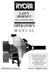
Transcript
-
TMESE INSTRUCTIONS MAY BE USED FN MORE THAN ONE KIT PLEASE REAP CAREFULLY BEFORE INSTALLfNG BALL JOINT
WARNING: Befure aitempting to-remove stud F
msteering knuckle, makesure the stud of the old ball joint was firmly seated in
the tapered hole of the steering knuckle. H the ball joint stud was loose-inthe steering knuckle, or if any out-of-roundness, deformation or damage is obsewed, the STEERING KNUCKLE MUST BE REPLACED. Failure to replace a damaged or worn steering
knuckle may cause loss of steering ability because the ball joint STUD MAY BREAKand cause the wheel to separate from the
vehicle.
NOTE.-The parts in this kit are desiglned to replace the worn or non-functioning original equipment parts in the vehicfeas produced
by the car factory. These parts are not designed for installation on vehicles where the suspension andlor steering systerns.have
been modified for racing, competition, or any ether purpose.
1. With vehicie firmly suppopted under tower control arm, remove tapered stud from steering knuckle with suitable taper breaker
tool (never strike knuckle with hammer) and remove bal! joint from control arm with suitable tool. Examine ball joint contact area
of arm and make sure it is dean and free of cracks. WARNING: Ifany clacks or damage is found, the CONTROL ARM MUST
BE REPLACED. Failure to repla& a cracked or damaged control arm may cause lass of steering ability because the CONTROL ARM MAY BREAK and catlse the wheel to separate from the vehicle.
2. Clean steering knuckle taper. Insert the new ball joint stud into the steering knuckle by hand and check the fit of €hestud taper
to the knuckle. Stud should seat firmly without rocking. Only threads should extend through the steering knuckle. If the parts do
not meet these ae'quirements, either the steering knuckle is worn and needs replacement, or incorrect par& are being used.
3. Affer examining control am and steering knuckle and verifying these parts are reusable, proceed with installation by threading
ball joint squarely into control arm until shoulder of ball joint is firmly seated against arm. M ) NOT cross thread ball joint into
control arm.
4. ti toque required to seat the housing is lessthan 125 it.-lbs, the control arm must be replaced, Slide dust boot supplied over
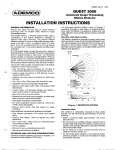
stud and onto housing, then insert stud into steering knuckle, install washer if supplied only i f a washer is en the car as original
equipment {see illustration below). Improper use of washer will cause misalignment of nut slots and cotter pin hole.
5. Install slotted nu3 supplied and torque to the vehicie manufacturer's recommended specificationsas shown in the original equipment service manual. When the torque specification has been reached for the particular size thread being tighten, lacate cotter
pin hole in stud and then continue to tighten until first available slot in nut lines up with hole in gud. MVER BACK OFF NUT
-- TO ALIGN C O E R PIN HOLE;always continue tightening to next available slot. Install and spread cotter pin.
6. Install grease fitting supplied into ball joint and grease unit with a good g r a m t h i i s i s m?lEant Install whed-andtire, r e m G d '
support from underneaih lower ccrntrol arm, and lower vehicle to floor.
7. Align front-end to specificatior~s.Wheel balancing is recommended. Check front wheel bearings for proper adjustment
IMPROPER INSTALLATION
WITHOUT WASHER
(NOTE CO-ER PfSd HOLE)
IMPROPER INSTALLATION
WITH WASHER
(NOTE GOITER PFN HOLE)
PROPER INSTALLATION
WITH OR WITHOUT WASHER
(NOTE COlTER PIN HOLE)
SPECIAL N O T E
STEERING KNUCKLE WEAR CAN CAUSE BALL JOINT STUD BREAKAGE
THE STEERING KNUCKLE MUST BE
REPLACED IN ANY AM ALL CASES OF
BALL JOINT STUD BREAKAGE.
THE STEERING KNUCKLE MUST BE
REPLACED IF ANY TEST INDlCATES AM
"OUT-OF-ROUND OR "FREITED TAPER