1
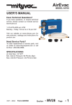
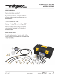
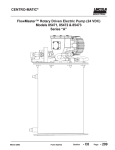
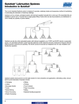
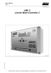
PNEUMATIVAC
8.8 Liter/9.3 Quarts Capacity
MODEL 07300
8.8 liter
Reservoir
Tank
Brake
Bleeder
Dipstick
Tubes
OCT - 2003
Form 822643
Section
- MV12 Page - 1
Always read instructions carefully prior to use.
Recommended Fluids:
Engine Oil, Gear and Transmission Oils, Power Steering Fluid, Coolants, Brake Fluid and Other Fluids.
Do not use with gasoline.
Using the PneumatiVac away from a Compressed Air Source
The PneumatiVac is equipped with an air control valve on the Venturi at the base of the unit and an in-line
fluid shut off valve on the hose assembly. This allows the unit to function away from the air source as
follows:
• Once the compressed air source has been connected to the Venturi, open the air control valve and close
the in-line fluid shut off valve.
• Maintain a vacuum in the reservoir and then close the air control valve.
• Disconnect the PneumatiVac from the compressed air source and transport it to your job site.
• Open the in-line fluid shut off valve and the vacuum stored in the reservoir will automatically suction out
the fluid.
When used in conjunction with the Mityvac® Fluid Evacuator Brake Bleeding Accessory Kit, PIN 07205,
this tool can be used to vacuum bleed hydraulic brake systems.
The reservoir tank of the Pneumativac is equipped with an automatic shut-off valve to prevent over-filling of
the reservoir tank. As the fluid being evacuated flows into the reservoir tank it will raise the float. When the
float reaches the shut-off valve, the flow of fluid being extracted will automatically stop.
Extracting and Dispensing Lubricants (General)
(Motor oil, Gear Oil, Transmission Fluid, etc.)
Extracting and Dispensing Motor Oil into a Crankcase
1. Park vehicle on level ground, ensure the transmission of the vehicle is in “neutral” or “park” position
and apply the parking brake.
2. Start the engine. Allow the engine to idle until it reaches normal operating temperature. Once this is
accomplished, turn engine off.
3. Remove the engine oil dipstick.
4. Select and insert the smallest diameter dipstick tube into the dipstick hole until it reaches the bottom
of the oil pan. Connect the main suction tube to the dipstick tube.
5. Insert the opposite end of the main suction tube into the top of the reservoir tank.
6. Connect air hose to the venturi at the base of the PneumatiVac. This will require a male 1/4" NPT
fitting (not included).
7. Open the air valve thereby creating a vacuum inside the reservoir tank that will be used to extract the
fluids.
NOTE: Due to the varying fluid capacities of engines, it may be necessary to empty the fluid reservoir
tank and restart the process if the crankcase capacity exceeds 8 liters.
Page Number - 2
Form 822643
8. Once the oil has been extracted from the crankcase, remove the main suction tube from the reservoir
tank; pour the oil from the tank into a suitable container, and dispose of the oil in an appropriate manner. Rinse out the reservoir tank with clean solvent or engine degreaser. Allow it to dry thoroughly.
9. Refilled the crankcase to the desired level.
10. Run the engine momentarily to circulate the new oil and then recheck the level to ensure that it is at
the “full” mark.
Extracting and Dispensing Fluid into Transmission Cases and Differentials
1. Follow Steps 1 & 2. (See Extracting and Dispensing Motor Oil into a Crankcase)
2. Remove the transmission fluid dipstick or fill plug.
In some applications this may require jacking or lifting the vehicle. Use appropriate
safety stands to avoid serious or fatal injury.
3. Select and insert the appropriate diameter dipstick tube into the dipstick fill hole until it reaches the
bottom of the transmission pan or gear case. Connect the main suction tube to the dipstick tube.
4. Insert the opposite end of the main suction tube into the top of the reservoir tank.
5. Connect air hose to the venturi at the base of the PneumatiVac. This will require a male 1/4" NPT
fitting (not included).
6. Open the air valve thereby creating a vacuum inside the reservoir tank that will be used to extract the
fluids.
7. Once the desired amount of fluid has been extracted, close the air control valve to stop the extraction
process.
8. Remove the main suction tube from the reservoir tank; pour the transmission fluid from the tank into a
suitable container, and dispose of the transmission fluid in an appropriate manner. Rinse out the
reservoir tank with clean solvent or engine degreaser. Allow it to dry thoroughly.
9. Refill the transmission to the desired level.
10. Run the engine until it reaches operating temperature to circulate the new fluid and then re-check the
level to ensure that it is full.
Extracting and Dispensing Coolant into a Cooling System
1. Allow the engine to cool.
2. Remove the radiator I expansion tank cap.
3. Select the largest diameter dipstick tube and insert the tube into the radiator neck or expansion tank.
4. Insert the opposite end of the main suction tube into the top of the reservoir tank.
5. Connect air hose to the venturi at the base of the PneumatiVac. This will require a male 1/4" NPT
fitting (not included).
Form 822643
Page Number - 3
6. Open the air valve thereby creating a vacuum inside the reservoir tank that will be used to extract the
fluids.
7. Once the desired amount of fluid has been extracted, close the air control valve to stop the extraction
process.
8. Remove the main suction tube from the reservoir tank; pour the fluid from the tank into a suitable
container, and dispose of the fluid in an appropriate manner. Rinse out the reservoir tank with clean
solvent or engine degreaser. Allow it to dry thoroughly.
9. Refill the system to the desired level.
10. Run the engine until it reaches operating temperature to circulate the new fluid and then re-check the
level to ensure that it is full.
Extracting Brake Fluid from the Master Cylinder
1. Clean the exterior of the master cylinder and master cylinder cap. (This will prevent dirt from entering the
master cylinder reservoir when the cap is removed.)
2. Remove the lid of the master cylinder reservoir.
Prior to inserting the extraction tube into the master cylinder reservoir, be sure that the
extraction tube is clean and free of any other types of fluid. Failure to do so would result
in contamination of the brake fluid in the hydraulic system and cause potential brake
failure.
3. Select the appropriate “dipstick” tube and connect it to the main suction tube.
4. Insert the opposite end of the main suction tube into the top of the reservoir tank.
5. Insert the end of the extraction tube into the master cylinder reservoir.
6. Connect air hose to the venturi at the base of the PneumatiVac. This will require a male 1/4" NPT
fitting (not included).
7. Open the air valve thereby creating a vacuum inside the reservoir tank that will be used to extract the
fluids.
6. Once the break fluid has been extracted, remove the main suction tube from the reservoir tank; pour
the break fluid from the tank into a suitable container, and dispose of it in an appropriate manner. Rinse
out the reservoir tank with clean solvent or engine degreaser. Allow it to dry thoroughly.
7. After all repairs are accomplished, refill the system with new, manufacturer approved brake fluid from
a sealed container.
MAXIMUM TEMPERATURE OF FLUIDS: 176° Fahrenheit, 80° Celsius
Page Number - 4
Form 822643
Rubber Connector
Tank Connector
Control Valve
Brake Bleeding Adapter
Bleeding Brakes
Instructions for Setup:
1. Select the brake bleeding hose and connect one end to the in-line fluid shut off valve. Connect the
main connector to the reservoir tank and the universal bleeding elbow to the bleeder screw.
2. Close the in-line fluid shut off valve (handle of valve will be turned 90 degrees from hose).
3. Connect air hose to the Venturi at the base of the PneumatiVac. This will require a male 3/4" NPT
fitting that is used with your system (not included).
4. Open the air shut off valve thereby creating a vacuum inside the reservoir tank that will be used to
bleed the brakes.
The following brake bleeding procedure is recommended:
1. Ensure master cylinder reservoir is full of the specified fluid and new dean fluid is available to top off
reservoir during bleeding procedure. Ensure all bleeder fittings are clean at the start of bleeding
procedure.
2. Bleed system in the following order:
a. Master cylinder (if necessary). See the Bench Bleeding Procedure below if a new or rebuilt master
cylinder is being installed.
b. ABS controller (if necessary).
c. Wheel cylinders and calipers in succession beginning with the wheel closest to the master cylinder
and working to the farthest one.
3. Place wrench on the nut of the bleeder screw.
4. Connect brake bleeding adapter onto bleeder screw.
5. Open the air shut off valve by turning it to the “OPEN” position, thereby creating a vacuum required for
bleeding.
6. Open the bleeder screw slightly, only enough to cause fluid to flow into the bleeder hose and continue
into the PneumatiVac™ (usually 1/4 to 1/2 turn).
7. After evacuating, approximately 1/4 of the master cylinder reservoir capacity, tighten the bleeder
screw. Add new brake fluid to the master cylinder so it remains full then proceed to the next wheel.
NOTE: A tiny stream of bubbles may be noted in the bleeder hose after the bleeding procedure. This is
caused by air seeping around the threads of the loosened bleeder screw and is drawn through
the fitting by the suction created by the Fluid Evacuator. Once the air has been removed from
the system, these tine air bubbles DO NOT jeopardize the bleeding operation since they are only
present at the external surface of the floeder fitting and not in the system. If desired, bleeder
fitting threads may be sealed with Teflon® tape to help eliminate this condition.
NOTE: When finished using the PneumatiVac, contents should be emptied into an approved waste
container. Rinse reservoir with water, or solvent where applicable.
Form 822643
Page Number - 5
Bleeding Anti-Lock Brake Systems
Always refer to the vehicle’s owner manual or the appropriate service manual for manufacturer’s brake
bleeding procedure. The front brakes on most anti-lock brake systems may be bled in the conventional
manner. Most hydraulic pump/pressure accumulator units are fitted with a bleeder valve, which must be
bled when the system has lost fluid or is being replaced. Some vehicles require that the system be
pressurized when the rear brakes are bled. Acura, Ford and General Motors require a bleeding
procedure, which uses specialized equipment.
Bench Bleeding System
Whenever a master cylinder has been removed from a vehicle or a new one is being installed, the
master cylinder must be bench bled. Failure to bench bleed is the main reason for unsuccessful master
cylinder replacement. Bench bleeding greatly decreases the chance that any air will be caught in the
cylinder upon reinstallation. Most manufacturers include a bench bleeding kit with new or remanufactured
master cylinders. If this kit was not included with the replacement part to be installed, consult with your
retailer prior to installing the new or rebuilt master cylinder on the vehicle.
Item Description
1 Brake Bleeding Adapter *
Part No.
822559
* Consists of three adapters
Page Number - 6
Form 822643
Model 07300 Service Items
Item Description
Part No. Item Description
1 Vaccum Tube Kit
822599
2 Kit, Exhaust Muffler*
822644
3 Kit, Control Valve
822645
4 Kit, Tube and Connectors
822646
* Consists of three mufflers
** Consists of venturi and connectors
*** Consists of base and foot bracket
**** Consists of top and overfill float
Form 822643
5
6
7
Kit Venturi**
Base Kit***
Kit, Lid and Float****
Part No.
822647
822574
822648
Page Number - 7
LIMITED WARRANTYLincoln warrants the equipment it supplies to be free from defects in material and workmanship for one (1)
year following the date of purchase. If equipment proves to be defective during this warranty period it will be
repaired or replaced, at Lincoln’s discretion, without charge provided that factory authorized examination
indicates the equipment to be defective. To obtain repair or replacement, you must ship the equipment,
transportation charges prepaid, with proof of date of purchase to a Lincoln authorized warranty and service
center, within one (1) year following the date of purchase.
LIMITED 5 YEAR WARRANTY (Series 20, 25, 40 Bare Pumps, Heavy Duty and Golden Standard Bare
Reels)Lincoln warrants series 20, 25, 40 bare pumps, and heavy duty and golden standard bare reels it supplies to
be free from defects in material and workmanship for one (1) year following the date of purchase. If equipment proves to be defective during the warranty period it will be repaired, or replaced, at Lincoln’s discretion,
without charge provided that factory authorized examination indicates the equipment to be defective. To
obtain repair or replacement, you must ship the equipment, transportation charges prepaid, with proof of
purchase to a Lincoln Authorized Warranty and Service Center within one (1) year following the date of
purchase. Additionally, in years two (2) and three (3) the warranty on this equipment is limited to repair with
Lincoln paying parts and labor only. In years four (4) and five (5), the warranty on this equipment is limited to
repair with Lincoln paying for parts only.
This warranty is extended to the original retail purchaser only. It does not apply to equipment damaged from
accident, overload, abuse, misuse, negligence, faulty installation or abrasive or corrosive material, or to
equipment repaired or altered by anyone not authorized by Lincoln to repair or alter the equipment. This
warranty applies only to equipment installed and operated according to the recommendations of Lincoln or
its authorized field personnel. No other express warranty applies.
Any implied warranties applicable to equipment supplied by Lincoln, including the warranties of merchantability and fitness for a particular purpose, will last for only one (1) year from the date of purchase. Some
jurisdictions do not allow limitations on how long an implied warranty lasts, so the above limitation may not
apply to you.
In no event shall Lincoln be liable for incidental or consequential damages. Lincoln’s liability on any claim for
loss or damages arising out of the sale, resale or use of equipment it supplies shall in no event exceed the
purchase price. Some jurisdictions do not allow the exclusion or limitation of incidental or consequential
damages, so the above limitation or exclusion may not apply to you.
Americas:
One Lincoln Way
St. Louis, MO 63120-1578
USA
Phone +1.314.679.4200
Fax +1.800.424.5359
Page Number - 8
Europe/Africa:
Heinrich-Hertz-Str 2-8
D-69183 Walldorf
Germany
Phone +49.6227.33.0
Fax +49.6227.33.259
Asia/Pacific:
25 Int’l Business Park
#01-65 German Centre
Singapore 609916
Phone +65.562.7960
Fax +65.562.9967
© Copyright 2003
Printed in USA
Web site:
www.lincolnindustrial.com
Form 822643