1
STANDARDS
AND
2.4
GUIDELINES FOR COMMUNICATION SITES
•
Excavating and installing tower foundations
•
Installing equipment shelter and ancillary equipment, including backup power systems
•
Installing electrical conductors and other utility installations
•
Energizing equipment shelter
•
Installing tower, antennas and RF transmission lines
•
Installing tower lighting system
•
Installing fencing and gates
•
Backfilling, grading, and bringing site up to final grade
•
Startup and testing of facility equipment
•
Performing final cleanup and obtaining customer approval signatures
PLANNING
PLANNING
Planning the development of a communications site is crucial because the activities involved in
constructing a site must be effectively organized in order to complete the project efficiently.
2.4.1
LOCATION OF UTILITY ENTRANCES
All utility entrances (i.e., AC power, phone company, RF cables, water supply, gas supply, etc.) to the
facility should be located in the same general area of the shelter and should be located as close together
as is practical.
2.4.2
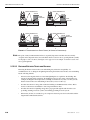
LOCATION OF AC POWER NEUTRAL-GROUND BOND
Equipment performance and the susceptibility of a communications site to damage from lightning are
affected by the location of the AC power neutral-ground bond. See “Location of Neutral-Ground Bond”
on page 6-4.
2.4.3
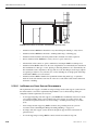
SITE DEVELOPMENT DRAWINGS
To help ensure that site development plans are developed in accordance with jurisdictional codes and
specifications, it is highly recommended that an engineering firm be consulted.
Typical site development drawings should include (but not be limited to) the following:
68 P 81 08 9E 5 0- B
9 / 1/ 0 5
•
General compound and site layout relative to the surroundings
•
Location of access road if applicable
•
Location of existing utilities
•
Road profiles (cut and fill requirements)
•
Existing road profile
2-3