1
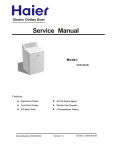
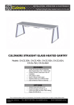
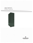
Order No. TL1206S003V1.1
Gas Dryer
Model No.GDG480BW
©2008 Haier Washing Machine
Service Manual
Issue
Rev.
Order No. TL1206S003V1.1
Chapter 1: General Infromation
Document control ......................................................................................................... 1
Chapter 1. General Information
............................................................................... 2
1-1. Table of Contents
2
1-2. General Guidelines
3
1-3. Caution and Warning symbols
3
1-4. Function indication symbols
3
Chapter 2. Product Feature ....................................................................................... 4
2-1. Features
4
2-2. Specification
5
..................................................................... 6
Chapter 3. Matters needing attention
3-1. Safety
6
3-2. During Use
8
........................................................................ 10
Chapter 4. Operational Guidance
4-1. Understanding the Control Panel
10
4-2. Auto Dry cycles
10
4-3. Timed Dry cycle
10
Chapter 5. Drying Mathods ....................................................................................... 11
5-1 Preparations before drying
11
5-2 Load clothes into dryer
11
5-3 Selecting Drying program
11
Chapter 6. Appearance brief introduction ................................................................... 12
12
6-1. Name of parts
6-2. Net dimension
12
Chapter 7. Disassembly and Installation ................................................................. 13
13
7-1. Remove packing materials
13
7-2. Adjusting the Dryer
13
7-3. Location of your dryer
13
7-4. Installation in Alcove or Closet
14
7-5. Manufacation (mobile) home installation
14
7-6. Electrical Installation
15
7-7. Manufactured (Mobile) Home Hold Down Kit
16
7-8. Natural Gas to LP Gas Conversion Kit
19
7-9. Gas connections
20
7-10. Connecting to the Gas Supply
Chapter 8. Wiring circuit and Self check
............................................................ 21
8-1. Wiring circuit
21
8-2. Self check
21
Chapter 9. Error Display and troubleshooting ....................................................... 22
22
9-1. Error Display
23
9-2. Examination & Troubleshooting
23
9-2-1. Display nothing
23
9-2-2. The computer is power onˈbut the dryer no action
24
9-2-3. The drum rotates but the dryer have no drying
24
9-2-4. The dryer drying but clothes can’t intensive drying
25
9-2-5. Too much noise in drying
-2-
1
1-1. Table of Contents
Service Manual
Issue
Rev.
Order No. TL1206S003V1.1
1-2. General Guidelines
1
When servicing,observe the original lead dress.If a short circuit is found, replace all parts which are
overheated or damaged by the short circuit.After servicing ,see to it that all the protective devices
such as insulation barriers ,insulation papers shields are properly installed .Confirm that the screws,
parts and wiring which were removed in order to service are put in the original positions, or whether
there are the portions which are deteriorated around the service places serviced or not. And be sure
safety of that.
1-3. Caution and Warning symbols
Most important thing is to list up the potential hazard or risk for the service personnel to open
the units and disassemble the units. For example, we need to describe properly how to avoid
the possibility to get electrical shock from the live power supply or charged electrical parts (even
the power is off).
This symbol indicates that there are important operating and maintenance instructions
in the literture accompanying the appliance.
1-4. Function indication symbols
(You will see them in the specification table)
This symbol indicates that there are important operating and maintenance instructions
Signify the dryer doesn’t have this function.
-3-
Service Manual
Issue
Rev.
Order No. TL1206S003V1.1
Chapter 2
Product Feature
2-1. Features
All dryers come with a lint filter that needs to be cleaned before or after every use (read
“Care and Cleaning Guide” Section).
(2).Leveling Legs:
Your dryer has four leveling legs which are located in the front and rear corners of your
dryer. After installing your dryer in its final position, you can level your dryer.
Leveling legs can be adjusted by turning them clockwise to raise your dryer or by turning
them counterclockwise to lower your dryer.
(3).End of Cycle Signal:
• At the end of the dry cycle an audible signal will beep to alert you that the dryer has
completed drying the load.
(4).Wrinkle Saver:
• At the end of the dry cycle the dryer will automatically go into the wrinkle saver mode.
Here the dryer tub will tumble periodically for 1 hour after the dry cycle is completed.
To stop simply open the door and remove the clothes.
-4-
2
(1). Lint Filter:
Service Manual
Issue
Rev.
Order No. TL1206S003V1.1
2-2. Specification
2
GAS DRYER
GDG480BW
Brand
Haier
Color Availability
White
Electrical Requirements
120V/60Hz
Amps
8A
Capacities:Drum Size (Cubic Foot)
Drum Type
6.5
Painted
Motor Size (hp)
1/4
Power Cord Included(Attached)
●
Fuel Type
Gas
Controls
Rotary Control
Indicator Lights
Indicator Lights + Process Status
Temperature Settings
3
No Heat (Air Fluff)
●
Dry Sensor
Thermostat
Reversible Door
▬
End of Cycle Signal
●
Easy Access Lint Filter
●
Interior Drum Light
▬
Dryer Rack
▬
Auto Dry Cycles
4 (Heavy / Normal / Delicates)
Time Dry
● (10;30;60;90 )
Wrinkle Saver
●(Works upto I hr after every cycle)
Exhaust Vents
Rear Only
Leveling Legs
●(4)
LP Conversion Kit
●
Serviceable Front
●
Heating Element (watts)
20,000BTU
Unit Dimensions (In.)
Width
27''(686mm)
Depth With Door Close
28.3"(718mm˅
Depth With Door Open
50.6"(1285mm˅
Height
36''(915mm)
Height With Back Guard
43 1/4''(1097mm)
Unit Weight lbs.(approx)
128
Carton Dimensions (In.)
Height
46.97" (1193 mm)
Width
29.84" (758 mm)
Depth
30.16" (766 mm)
Shipping Weight lbs.(approx)
Container Quantity
90(40'H)
-5-
Service Manual
Issue
Rev.
Order No. TL1206S003V1.1
Chapter 3 Matters needing attention
Before beginning installation, carefully read these instructions. This will simplify
the installation and ensure the dryer is installed correctly and safely.
NOTE: The electrical service to the dryer must conform with local codes and
ordinances and the latest edition of the National Electrical Code, ANSI/
NFPA 70 or in Canada, CSA C22.1 Canadien Electrical Code Part 1.
NOTE: The gas service to the dryer must conform with local codes and
ordinances and the latest edition of the National Fuel Gas Code, ANSI
Z223.1 or in Canada, CAN/CGA B149.1.
NOTE: The dryer is designed under ANSI Z21.5.1 or ANSI/UL 2158 - CAN/
CSA C22.2 No. 112-97 (latest editions) for HOME USE ONLY. This
dryer is not recommended for commercial application such as restaurants,
beauty salons, etc.
WARNING - To reduce the risk of fire, electric shock, or injury to persons when using
your appliance, follow the basic precautions, including the following:
1. Read all of the instructions before using this appliance.
2. Don’t dry articles that have been previously cleaned in, washed in, soaked in, or
spotted with gasoline, dry clean solvents or other flammable explosive sub stains
as they give off vapors which could ignite or explode.
3. Do not allow children to play on or in the appliance. Close supervision of children
is necessary when the appliance is used near children
4. Before the appliance is removed from service or discarded, remove the door to
the drying compartment.
5. Do not reach into the appliance if the drum is moving.
6. Do not install or store this appliance where it will be exposed to water and/or to
the weather.
7. Do not tamper with controls.
8. Do not repair or replace any part of the appliance or attempt any servicing unless
specifically recommended in the user-repair instructions that you understand and
have skills to carry out.
9. Do not use fabric softeners or products to eliminate static unless recommended
by the manufacturers of the fabric softener or product.
10. Do not use heat to dry articles or products to eliminate static unless recommended
by the manufacturers of the fabric softener or product.
11. Clean lint screen before or after each load.
12. Keep area around the exhaust opening and adjacent surrounding areas free from
the accumulation of lint, dust and dirt.
13. Keep the dryer area clear and free from items that would obstruct the flow of
combustion and ventilation air through the louvered panel located on the rear of
the dryer.
14. The interior of the appliance and the exhaust duct should be cleaned periodically
by qualified service personnel.
-6-
3
3-1. Safety
Service Manual
Issue
Rev.
Order No. TL1206S003V1.1
Chapter 3 Matters needing attention
15. Do not place items exposed to cooking oils in your dryer. Items contaminated with
cooking oil may contribute to a chemical reaction than could cause a load to catch fire.
3
16. If material has been used with any flammable liquids or solids, it should not used in
the dryer until all terraces of flammable liquids and its fumes have been removed.
17. This dryer must be properly installed in accordance with the installation instructions
before it is used. See grounding instructions in the installations sections.
18. Proper grounding must be ensured to reduce the risk of electric shock and force.
Check with a qualified electrician or service personnel if you are in doubt as to
whether the dryer is properly grounded.
19. Use the dryer only for its intended purpose: drying clothes.
20. Always disconnect dryer from electrical supply before attempting any service.
Disconnect power cord by grasping the plug, not the cord.
21. Replace worn power cord and/or loose plugs.
22. To reduce the risk of electric shock or fire, do not use extension cords or adapters
to connect dryer electrical power source.
WARNING
Risk of Fire:
1.Clothes dryer installation must be performed by a qualified installer.
2.Install the clothes dryer according to the manufacturer’s instructions and local codes.
3.Do not install a clothes dryer with flexible plastic venting materials.
If flexible metal (foil type) duct is installed,it must be of a specific type identified by
the appliance manufacturer as suitable for use with clothes dryers. Flexible venting
materials are known to collapse, be easily crushed,and trap lint.These conditions
will obstruct clothes dryer airflow and increase the risk of fire.
4.To reduce the risk of severe injury or death, follow all installation instructions.
Safety Warning:
1.Before starting installation, make sure that the gas shut off valve is in the off position.
2. All old gas connectors and gas piping should be discarded.
ELECTRICAL REQUIREMENTS
Circuit
Individual 15 Amp branch circuit fused with 15-Amp maximum time delay fuse or circuit breakers.
Power Supply
3 wire, 120 Volt, 1 Phase, 60Hz, AC
Power Supply Cord
The dryer is equipped with a 120 Volt 3-wire power supply cord.
Note: This dryer is equipped with a three-prong grounding plug for your protection against
shock hazard and should be plugged into a properly grounded three-prong receptacle.
Do not under any circumstance cut or remove grounding prong from plug.
-7-
Service Manual
Issue
Rev.
Order No. TL1206S003V1.1
Chapter 3 Matters needing attention
3-2. During Use
The following are specific requirements for proper and safe operation of your
dryer. Failure to follow these instructions can create excessive drying times
and fire hazards.
1. Do not use plastic flexible duct to exhaust the dryer. Excessive lint can build up inside exhaust
system and create a fire hazard and restrict air flow. Restricted air flow will increase drying time.
If your present system is made up of plastic duct or metal foil duct, replace it with a rigid or
flexible metal duct. Ensure present duct is free of any lint prior to installing dryer duct.
2. The dryer must not be exhausted into any gas vent, chimney, wall, ceiling or any concealed
space of a building. The dryer exhaust system MUST be exhausted to the outdoors. If the
dryer is not exhausted outdoors, some fine lint will be expelled into the laundry area. An
accumulation of lint in any area of the home can create a health and fire hazard.
3. Exceeding the length of duct pipe or number of elbows allowed in the “Maximum Length”
chart can cause an accumulation of lint in the exhaust system. Plugging the system could
create a fire hazard, as well as increase drying times.
4. Do not screen the exhaust ends of the vent system. Lint can become caught in the screen,
increasing drying time. Use an approved vent hood to terminate the duct outdoors, and seal
all joints with duct tape.
5. All male duct pipe fittings must be installed downstream with the flow of air.
6. Exhaust duct must not be connected or secured with screws or other fastening
devices which extend into the interior of the duct.
7. Do not allow combustible material (clothing, draperies/curtains, paper, etc.) to come in contact
with exhaust system.
Explosion hazard
Do not install the dryer where gasoline or other flammables are kept or stored. If the dryer
is installed in a garage, it must be a minimum of 18 inches (45.7cm) above the floor. Failure
: in death, explosion, fire or burns.
to do so can result
Exhaust Requirements:
Use only 4 inch (10.2cm) diameter (minimum) rigid of flexible metal duct and approved vent
hood which has a swing-out damper hat open when the dryer is in operation. When the dryer
stops, the dampers automatically close to prevent drafts and the entrance of insects and
rodents. To avoid restricting the outlet,maintain a minimum of 12 inches (30.5cm) clearance
between the vent hood and the ground or any other obstruction. The vent flap should be able
to move freely, although vertical orientation of the exhaust system is acceptable. Certain
extenuating circumstances could affect the performance of the dryer:
1. Only rigid or flexible metal duct work should be used.
2. Venting vertically through a roof may expose the exhaust system to down drafts causing an
increase in vent restriction
3. Running the exhaust system through an uninsulatedarea may cause condensation and faster
accumulation of lint.
4. Compression of crimping of the exhaust system will cause an increase in vent restriction.
5. In Canada, that only those foil-type flexible ducts, if any, specifically identified for use with the
appliance by the manufacturer shall be used. In the United States, that only those foil-type
flexible ducts, if any, specifically identified for use with the appliance by the manufacturer and
that comply with the UL Outline for Clothes Dryer Transition Duct, Subject 2158A (2006),
shall be used.
-8-
3
EXHAUST SYSTEM REQUIREMENTS
Service Manual
Issue
Rev.
Order No. TL1206S003V1.1
Chapter 3 Matters needing attention
6. In Canada, that the exhaust duct shall be 102 mm in diameter. In the United
States, the required exhaust duct diameter;
7. The total length of flexible metal duct shall not exceed 2.4 m.
3
The exhaust system should be inspected and cleaned a minimum of every 12
months with normal usage. The more the dryer is used the more often you
should check the exhaust system and vent hood for proper operation.
RECOMMENDED MAXIMUM
Exhaust Hood Types
Recommended
Use only for short run installations
No. of 90º elbows
Rigid Metal
Rigid Metal
0
90 ft.
60 ft.
1
60 ft.
45 ft.
2
45 ft.
35 ft.
3
35 ft.
25 ft.
Note: Exhausting refers to removal of moist air from the drying compartment.
Gas supply requirements
WARNING Replace copper connecting pipe that is not plastic-coated. Stainless steel or
plastic-coated brass MUST be used.
1.Installation MUST conform with local codes. In the absence of local codes, installation must
conform with the National Fuel Gas Code, ANSI Z223.1 (latest edition) or in Canada, the
current CAN/CGA B149.1
2. The gas supply line should be 1/2 inch (1.27cm) pipe.
3. If codes allow, flexible metal tubing may be used to connect your dryer to the gas supply line.
The tubing MUST be constructed of stainless steel or plastic-coated brass.
4. The gas supply line MUST have an individual manual shutoff valve installed within 6 feet
(183cm) of the dryer in accordance with the National Fuel Gas Code, ANSI Z223.1/NFPA 54.
In Canada, an individual manual shut-off valve MUST be installed in accordance with the
B149.1, Natural Gas and Propane Installation Code.
5. A 1/8 inch (0.32cm) N.P.T. plugged tapping, accessible for test gauge connection, MUST be
installed immediately upstream of the gas supply connection to the dryer.
6. The dryer MUST be disconnected from the gas supply piping system during any pressure
testing of the gas supply piping system at test pressures in excess of 1/2 psig (3.45kPa).
7. The dryer MUST be isolated from the gas supply piping system during any pressure testing of
the gas supply piping system at test pressures equal to or less than 1/2 psig (3.45 kPa).
-9-
Service Manual
Issue
Rev.
Order No. TL1206S003V1.1
Chapter 4 Operational Guidance
4
Understanding the Control Panel
1
3
4
2
5
Temp Button: (1)
● Use to set drying temperatures.There are four available drying temperatures to choose from:High,Medium,Low
and No Heat.
Dry Level Button: (2)
● Used to set drying level.There are three available drying levels to choose from More,Normal and Less.
Cycle Select Dial:(3)
● Select from 3 Auto-Dry cycles (Heavy Duty , Normal and Delicates) or 4 Timed Dry Cycles
(10min,30min,60min,90min) or “Off” to shutdown the machine.
Start/Pause Button (4)
● Push to shart after selecting the dry cycle and seting the temperature . Push once to pause . Push again to start
after pushing
Cycle Progress:(5)
:
● This indicates the process
the cycle is currently in . At the end of cycyle the dryer will automatically go in the wrinkle
saves mode . Here the dryer tub will tumble periodically for 1 hour after the dry cycle is completed . To stop simply
open the door and remove the clothes.
Note : Clean the lint filter before every use .
- 10 -
Service Manual
Issue
Rev.
Order No. TL1206S003V1.1
Chapter 5 Drying Mathods
5-1. Preparations before drying
5
• Sort clothes of the same kind (cotton, synthetics, woolen) to dry.
• Dark and light colored clothes should be separately dried. Fabrics prone to
losing lint and those prone to adhering lint shall be separately dried. Clothes
prone to falling lint should be turned inside out before putting into the dryer.
• Make sure buttons and ornaments on the clothes are high temperature
resistant and won’t damage drum surface. Before loading, the clothes should
have their zippers zipped up, buttons and hooks done up and belts tied so as to
avoid entanglement or other obstacles.
• If possible, turn out the clothes pockets for uniform drying.
• Check if clothes remain soiled. If so, wash them again, otherwise soils may be permanently set.
• Small articles should be collected in a mesh bag before loading and drying, so as to avoid
entanglement and ensure easy removal.
• Make sure the power socket is reliably grounded. The grounding terminal should not be
connected to gas or tap water pipelines.
• Make sure exhaust duct has been properly connected.
• Make sure lint filter is clean and properly installed. If lint filter is not in place, tumbling items
could enter the exhaust system and cause damage to the dryer.
Note: Applies to Auto Dry cycle and Timed Dry cycle.
5-2. Load clothes into dryer
• The appropriate load should be 1/3 ~ 1/2 of the drum volume. Avoid too much load, as space
is needed to allow clothes free rotation for uniform and wrinkle-proof drying.
• When drying big articles, only 2-3 pieces should be loaded at a time and supplemented with
.small and medium-sized articles.
• For delicate clothes or less load, two towels may be added to get better drying and wrinkle-proof
effects.
• Do not excessively dry clothes to avoid wrinkles, shrinkage, roughness, electro-static charge
accumulation, and/or more lint.
5-3. Selecting Drying program
To get the best drying effect, an appropriate drying program should be selected according to
the laundry type.
- 11 -
Service Manual
Issue
Rev.
Order No. TL1206S003V1.1
Chapter 6 Appearance brief introduction
6
6-1. Name of parts
6-2. Net dimension
- 12 -
Service Manual
Issue
Rev.
Order No. TL1206S003V1.1
Chapter 7 Disassembly and Installation
7-1. Remove packing materials
7
1. Remove all packaging material. This includes the foam base and all adhesive
tape holding the dryer accessories inside and outside.
2. Inspect and remove any remains of packaging, tape or printed materials
before using the dryer.
7-2. Adjusting the Dryer
There are adjustable feet under the bottom of the
dryer. Before use, the dryer should be adjusted,
as shown in the right figure, so that it is level.
7-3. Location of your dryer
Do Not Install Your Dryer:
1. In an area exposed to dripping water or outside weather conditions.
2. In an area where it will come in contact with curtains, thick carpet, or anything
that will obstruct the flow of combustion and ventilation air.
3. On carpet, floor must be solid with a maximum slope of 1inch (2.54 cm). Any
floor unevenness should be corrected with leveling legs located on the bottom
of the dryer.
7-4. Installation in Alcove or Closet:
1. DO NOT install your dryer in a closet with a solid door.
2. A dryer installed in a bedroom, bathroom, alcove or closet MUST be exhausted outdoors.
3. No other fuel burning appliance shall be installed in the same closet as the gas dryer.
4. Refer to the images on this page to ensure the installation provides the minimum amount of
clearance required for ventilation.
5. When installing the dryer in a closet with a door, a minimum of 120 square inches (774.2
square cm) of ventilation in the door is required. Openings must be equally divided at the
top and bottom of the door and airflow must be unobstructed. A louvered door with
equivalent air openings for the length of the door is acceptable.
- 13 -
Service Manual
Issue
Rev.
Order No. TL1206S003V1.1
Manufacation (mobile) home installation
1. Dryer MUST be exhausted outside (outdoors, not beneath the manufactured
home) using metal ducting that will not support combustion. Metal ducting must
be 4 inch (10.16 cm) in diameter with no obstructions. Rigid metal duct
is preferred.
2. If dryer is exhausted through the floor and area beneath the manufactured
home is enclosed, the exhaust system MUST terminate outside the enclosure
with the termination securely fastened to the mobile home structure.
3. When installing a gas dryer into a manufactured home, a provision must be
made for outside make up air. This provision is to be not less than twice the
area of the dryer exhaust outlet.
4. This dryer MUST be fastened to the floor using P/N 0030807899
Manufactured Home Installation Kit. Follow the instructions supplied with
the kit.
5. Refer to previous sections for other important venting requirements.
6. Installation must conform to current Manufactured Home Construction & Safety
Standard (which is a Federal Regulation Title 24 CFR-Part 32-80) or when
such standard is not applicable, with American National Standard for Mobile
Homes. In Canada, the CSA Z240 is applicable.
7-6. ELECTRICAL INSTALLATION
Gas dryers are equipped with a factory installed three-prong 15 Amps ~120
Volts (grounding) plug for your protection against shock hazard and should be
plugged directly into a properly grounded three-prong receptacle. Do not cut
or remove the grounding prong from this plug.
- 14 -
7
7-5.
Service Manual
Issue
Rev.
Order No. TL1206S003V1.1
Chapter 7 Disassembly and Installation
7-7. Installation Instructions
Manufactured (Mobile) Home Hold Down Kit No.0030807988
7
IMPORTANT
ARNING
Installation must conform to current Manufactured Home Construction & Safety Standard (which is a
Federal Regulation Title 24 CFR-Part 32-80) or when such standard is not applicable, with American
National Standard for Mobile Homes. In Canada, the CSA Z240 is applicable.
Dryer MUST be exhausted to the outdoors. Refer to the User Manual for dryer exhaust requirements.
Dryer MUST be permanently secured to the floor at the time of installation.
Parts List
4 0030101225 Hold Down Bracket
8 0030101240 #10 X 1/2Ž Wood Screw
1 0030502715A Installation Instructions
Installation Instructions
1. Place dryer in location where it is to be
installed. Refer to the User Manual for
information about locating your dryer.
NOTE: Allow adequate space between
the back of dryer and the wall to ensure
proper exhaust connection.
WALL
2. Level the dryer by adjusting the leveling
feet. Check with a carpenters level.
3. Assemble the exhaust duct to the dryer.
NOTE: The exhaust duct MUST NOT
terminate under the manufactured home.
The exhaust duct MUST be secured to
the structure. Refer to the User Manual
for complete exhaust requirements.
Measure the distance
from the wall to the
back of the dryer
4. Measure the distance from the back of
the dryer to the wall as shown in Figure 1.
Measure and mark the centerline of the
dryer as well. Note that the exhaust duct
connection to the dryer is located on the
dryer centerline.
Figure 1
5. Disconnect the exhaust duct and move
the dryer away from the wall, allowing
adequate room to work behind the dryer.
- 15 -
Service Manual
Issue
Rev.
Order No. TL1206S003V1.1
Chapter 7 Disassembly and Installation
8. Install the exhaust duct.
9. With the dryer in place, install the two remaining hold down brackets to engage the front
leveling feet.
WALL
11.0 in (280mm)
to edge of bracket
TOP VIEW
11.0 in (280mm)
to edge of bracket
Line indicating the distance
from the wall to the back of
the dryer
1.0 in (25mm)
to edge of
bracket
DRYER
CENTERLINE
1.0 in (25mm)
to edge of
bracket
Correct Bracket Orientation
Figure 2
7-8. Installation Instructions
Natural Gas to LP Gas Conversion Kit No. 0030807989
WARNING
WARNING
THIS CONVERSION KIT SHALL BE INSTALLED BY A QUALIFIED SERVICE AGENCY IN ACCORDANCE WITH THE
MANUFACTURER SINSTRUCTIONS AND ALL APPLICABLE CODES AND REQUIREMENTS OF THE AUTHORITY
HAVING JURISDICTION. THE INFORMATION IN THESE INSTRUCTIONS MUST BE FOLLOWED TO MINIMIZE
THE RISK OF FIRE OR EXPLOSION OR TO PREVENT PROPERTY DAMAGE, PERSONAL INJURY, OR DEATH.
THE QUALIFIED SERVICE AGENCY IS RESPONSIBLE FOR THE PROPER INSTALLATION OF THIS KIT. THE
INSTALLATION IS NOT PROPER AND COMPLETE UNTIL THE OPERATION OF THE CONVERTED APPLIANCE IS
CHECKED AS SPECIFIED IN THE MANUFACTURER S INSTRUCTIONS SUPPLIED WITH THIS KIT
.
- 16 -
7
Installation Instructions, Cont’d
6. Using the measurements from Step 4, install (2) 0030101225 Hold Down Brackets as shown
in Figure 2 using (4) 0030101240 #10 X 1/2” Wood Screw. Note the correct bracket orientation.
7. Move dryer back into place so that the rear leveling feet engage the hold down brackets.
Service Manual
Issue
Rev.
Order No. TL1206S003V1.1
Chapter 7 Disassembly and Installation
THE CONVERSION SHALL BE CARRIED OUT IN ACCORDANCE WITH THE REQUIREMENTS OF THE
PROVINCIAL AUTHORITIES HAVING JURISDICTION AND IN ACCORDANCE WITH THE
REQUIREMENTS OF THE CSA B149.1, INSTALLATION CODE.
Parts List
1
1
1
1
1
1
1
1
0030101224
0030101223
0030502706
0030502705
0030502705A
0030502704
0030502704A
0030502715
Regulator Blocking Plug
Main Burner Orifice No. 55
LP Gas Conversion Plate Sticker
LP Gas Conversion Service Sticker (English)
LP Gas Conversion Service Sticker (French)
LP Gas Valve Sticker (English)
LP Gas Valve Sticker (French)
Instructions
Regulator Blocking Plug
55
7
Important Note: Installation of this kit converts the dryer from use with Natural Gas to use with LP
Gas for altitudes up to 4,500 feet above sea level. For installations at an altitude greater than 4,500
feet above sea level, contact a qualified service agency for derating instructions.
Main Burner Orifice
Gas input - 20,000 BTU/HR
Before converting the dryer to LP Gas, verify
that the incoming gas supply line is equipped
with a pressure regulator (located ahead of the
dryer) that will maintain the gas supply to the
dryer at 12.5 ± 1.5" W.C. (31.8 ± 3.8cm W.C.)
Use a "U" tube manometer (or similar pressure
gauge) to check the pressure.
Motor Pulley
Drum Belt
Idler Pulley
Installation Instructions
1. Disconnect the electrical power
to the dryer.
2. Shut off the gas supply to the dryer.
3. Remove the louvered vent panel
on the rear of the dryer. Disengage the
drum belt by rotating the idler pulley
down and away from the motor. Slide
the belt off of the pulleys. (Figure 1)
Figure 1
4. Use a thin flat head screwdriver to disengage
the spring clips under the top cover.(Figure 2)
Figure 2
- 17 -
Service Manual
Issue
Rev.
Order No. TL1206S003V1.1
5. Prop open the top cover and remove the two
screws securing the front panel. (Figure 3)
6. While holding the outer rim of the drum, tip the
front panel forward and away from the drum
until it is no longer engaged. Slowly lower the
drum to its resting position.
7. Disconnect the Humidity Sensor wire harness.
Lift and remove the front panel and set it aside.
8. Remove the drum and belt and set them aside.
Figure 3
9. Remove the two screws that mount the burner
to the gas valve bracket. Remove the burner
and set it aside. (Figure 4)
CAUTION: Use care in removal to avoid
damage to the igniter.
10. Use a 3/8” box wrench to remove the existing
main burner orifice. Install the new main
burner orifice No. 55. (Figure 5). Torque the
new orifice to 30 in-lbs (3.4 N-m).
11. Remove the vent screw from the top of the
Figure 4
gas valve. Install the new regulator blocking
plug finger tight, then tighten it no more than
Apply No. 0030502704(A)
LP Valve Converted
Blocking Plug
1/8 turn to seal it. (Figure 5)
Sticker Here
12. Apply No. 0030502704 LP Gas Valve Converted
Sticker over the existing valve label. (Figure 5)
In Canada, apply No. 0030502704A (French).
13. Sign and date one of the No. 0030502705 LP
Gas Service Stickers and apply it adjacent to
the exiting dataplate on the rear of the dryer.
In Canada, apply No. 0030502705A (French).
#55 Orifice
14. Apply No. 0030502706 LP Gas Conversion Plate
Sticker adjacent to the existing dataplate on
Figure 5
the rear of the dryer.
15. Reinstall burner to gas valve bracket.
16. Remove the pressure tap plug from the gas valve body (Figure 6) and install a pressure
tap fitting finger tight.
17. Attach flexible tubing for “U” tube manometer to the pressure tap fitting. Run tubing out of the
rear of the dryer thru the vent panel opening.
Note: Tubing should be run under the exhaust duct to avoid contact with the drum.
- 18 -
7
Chapter 7 Disassembly and Installation
Service Manual
Issue
Rev.
Order No. TL1206S003V1.1
Chapter 7 Disassembly and Installation
7
18. Reinstall the drum and front panel. Tension
the drum belt.
19. Connect electrical service and turn on gas
supply to the dryer.
20. Check gas valve pressure as follows:
a. Connect manometer to tubing.
b. Start dryer using high temp setting.
c. Pressure should be 12.5±1.5” W.C.
d. Turn off the dryer.
21. Disconnect electrical service and shut off
gas supply to the dryer.
22. Repeat Steps 3 to 9. Remove the tubing
and pressure tap
fitting and replace pressure tap plug.
23. Turn on gas supply and check for leaks
using a soapy solution. Caution: Do not
use an open flame to check for gas leaks.
24. Shut off gas supply to the dryer.
25. Verify that the dryer conversion has been
completed. Recheck the following:
- Installed Main Burner Orifice #55 (Step 11)
- Installed Regulator Blocking Plug (Step 12)
- Verified gas inlet pressure is 12.5±1.5” W.C.
- Installed three stickers (Steps 13 to 15)
26. Reinstall the drum and front panel. Tension
the drum belt and reinstall the vent panel.
27. Connect electrical service and turn on gas
supply to the dryer.
Presure
Tap Plug
12.5 ± 1.5” W.C.
(31.8 ± 3.8cm W.C.)
“U” Tube
Manometer
Figure 6
7-9. Gas connections
NOTE: DO NOT connect the dryer to L.P. gas service without converting the gas
valve. An L.P. Conversion Kit must be installed by a qualified gas technician.
1.Remove the shipping cap from gas pipe at the rear of the dryer.
2.Connect a 1/2 inch (1.27cm) I.D. semi-rigid or approved pipe from gas supply line to
the 3/8 inch (0.96cm) pipe located on the back of the dryer. Use a 1/2 inch to 3/8
inch (1.27cm to 0.96cm) reducer for a connection. Apply an approved thread sealer
that is resistant to the corrosive action of liquified gases on all pipe connections.
3. Open the shutoff valve in the gas supply line.
4.Test all connections by brushing on a soapy water solution. NEVER TEST FOR GAS
LEAKS WITH AN OPEN FLAME.
5.Connect the exhaust duct to the outside exhaust system. Use duct tape to seal all joints.
6.With the dryer in its final position, adjust one or more of the legs until the dryer is resting
solid on all four legs. Place a level on top of the dryer. THE DRYER MUST BE LEVEL
AND RESTING SOLID ON ALL FOUR LEGS.
- 19 -
Service Manual
Issue
Rev.
Order No. TL1206S003V1.1
7.Plug the power cord into a grounded outlet. NOTE: check to ensure power is
circuit breaker/fuse box before plugging the power cord into the outlet.
8.Turn on the power at the circuit breaker/fuse box.
Before operating the dryer, make sure the dryer area is clean and free
from combustible materials, gasoline, and other flammable vapors. Also
see that nothing (such as boxes, clothing, etc.) obstructs the flow of
combustion and ventilation air through the louvered panel located on the
rear of the dryer.
9. Run the dryer through a cycle check for proper operation.
NOTE: On gas dryers, before the burner will light, it is necessary for the gas line to
be bled of air. If the burner does not light within 45 seconds the first time
the dryer is turned on, the safety switch will shut the burner off. If this
happens, turn the dryer to “Off” and wait 5 minutes before making
another attempt to light.
NOTE: Follow instructons supplied with kit.
7-10. Connecting to the Gas Supply
A) Connect female 3/8” NPT elbow to gas
inlet on dryer. Then connect 3/8” flare
union adapter to female elbow.
IMPORTANT: To prevent the inlet from
twisting, please use a pipe
wrench to secure the dryer
gas inlet. Affix Teflon®
tape or pipe compound to
adapter and gas inlet.
B) Attach the flexible metal gas line connector
to the adapter.
C) Make sure flexible gas line seal is secure.
Use two wrenches for the best possible
connection.
D) To check gas inlet pressure, attach 1/8”
NPT plugged tapping to dryer gas line shutoff valve. Then connect flare union adapter
to plugged tapping. Affix Teflon® tape
to the threads of the adapter and plugged
tapping to ensure seal.
E) Use two adjustable wrenches to tighten
every connection.
IMPORTANT: Do not overtighten!
F) Open gas shut-off valve.
- 20 -
7
Chapter 7 Disassembly and Installation
Service Manual
Issue
Rev.
Order No. TL1206S003V1.1
Chapter 8 Wiring circuit and Self check
White
Backup
Thermostat
Belt
Switch
Gray
Gray
Gray
Thermal
Limiter
Green
Black
8
White
8-1. Wiring circuit
Yellow
Blue
Black
Yellow
Computer Program
Controller
Door
Switch
Yellow
Moter
Yellow
Red
Gas
Valve
White
White
Igniter
Radiant
Sensor
High Limit
Thermostat
Cycling
Thermostat
Red
Brown
Black
8-2. WIRING DIAGRAM - GAS
Display self check: Press the buttons of “ Temp” and “ Start/pause” at the same time,
then all the LED ON 05s , OFF 0.5s and signal 0.5s , after 3 times repeats, dryer will
automatically off.
- 21 -
Service Manual
Issue
Rev.
Order No. TL1206S003V1.1
Chapter 9
S tart
Error Display
the dryerˈ the status lights is twinkling and the dryer no action
Error message: Door is not closed.
Troubleshooting:
Close the door
N
Confirm that the door is closed
Y
Cut off the power. Check if the wire
connecting door switch and PCB is
disconnection
Y
Connect the wire properly
N
Check if the Door switch is good.
Well:the resistence is 0Ω;
Broken: he resistence is infinite
broken
well
Check if the wire unit is good
Y
Replace the PCB
- 22 -
Replace the door switch and
make sure wire is connected
properly.
9
9-1.
Error Display and troubleshooting
Service Manual
Issue
Rev.
Order No. TL1206S003V1.1
Chapter 9
Error Display and troubleshooting
9-2. Examination & Troubleshooting
9-2-1. Display nothing
Troubleshooting:
Repair power supply
9
Measure the power supply ,is it
exists 120V AC voltage˛
N
Y
Cut off the power. Check if the wire
connecting wire unit and PCB is
disconnection
Y
Connect the wire properly
N
Check if the wire connecting power
line and wire unit disconnection
Connect the wire properly
Y
N
Check if the powerline and the
wire unit is good
Replace the powerline and
the wire unit
N
Y
Replace the PCB
9-2-2. The computer is power on and display rightˈbut the dryer no action
Troubleshooting:
Cut off the power .Check if the belt
is break off or the connecting of the
motor ǃbelt switch is loose
Y
Replace the belt or connect the
wire properly
N
Reinstall the tensive wheel unit
and try rotating the tub manually
N
Check if the tensive arm unit is
installed well
Y
Check if the belt switch is good.
Well: the resistance is 0Ω;
Broken: he resistance is infinite
-2broken
Replace the belt switch
well
Check if the back-up thermostat is
well. Well: the resistance is 0Ω;
Broken: he resistance is infinite
broken
Replace the back-up thermostat ,
insure that the exhaust system is
good
well
Check if the wire is well
N
Y
Replace the PCB
- 23 -
Replace the wire unit
Service Manual
Issue
Rev.
Order No. TL1206S003V1.1
Chapter 9
Error Display and troubleshooting
9-2-3. The drum rotates but the dryer have no drying
Check if the connecting the dryer to
the gas supply and the gas shut-off
valve is open, the gas supply accord
with the dryer’s requirements.
Connecting the dryer to the gas
supply, open the shut-off valve
insure the gas supply is well.
N
Y
Check if the wire connecting the
igniter ǃthe gas valve and the wire
unit is loose
Y
Connecting the wire properly
N
Check if the ignitor is well.
Well: the resistance is about
50Ω- 500Ω and not cracked;
Broken: the resistance is infinite
or cracked
Replace the ignitor, insure the
exhaust system is well
broken
N
Check if the wire connecting the
radiant sensorǃthe hi-limit thermostatǃ
the cycling thermostat and the wire unit
Connecting the wire properly
N
Y
Check if the radiant sensorǃthe
hi-limit thermostatǃthe cycling
thermostat is well.
Well: the resistance is 0Ω;
Broken: the resistance is infinite.
broken
well
Ω
Ω
Replace the
broken part
Ω
Check if the wire unit is well
Replace the wire unit
N
Y
Replace the PCB
9-2-4. The dryer drying but clothes can’t intensive drying
Troubleshooting:
Check if the exhaust system is up to
the mustard
Reinstall the exhaust system
N
Y
N
Check if the drum seal is airproof
- 24 -
If the drum seal is loose that
reinstall it; If the drum seal
broken that replace the
drum seal
9
Troubleshooting:
Service Manual
Issue
Rev.
Order No. TL1206S003V1.1
Chapter 9
Error Display and troubleshooting
9-2-5. Too much noise in drying
Troubleshooting:
9
Switch on the power, push down the
start button
N
Search the root of the noise
N
If the noise from the tensive arm unit
or the belt
Y
Reinstall the tensive arm
unit or replace the tensive
arm unit and the belt.
N
Check if some screw become flexible
Y
Fasten the screw
N
Check if is there gratings between
the impeller and the worm shell
Y
Replace the worm shell
N
Check if the drum can touch
something
Y
- 25 -
Reinstall them and liet the
drum can ’t touch anything
Sincere Forever
Haier Group
Haier Industrial Park, No.1, Haier Road
266101, Qingdao, China
http://www.haier.com
Printed in China