1
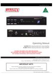
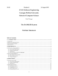
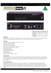
ALTRONIC AGV5
GAS METERING VALVE
SERVICE MANUAL
FORM AGV5 SM 11-03
ALTRONIC ,INC.
712 TRUMBULL AVE.
GIRARD, OHIO 44420
GAS METERING VALVE
AGV5-1
AGV5-1A
AGV5-2
AGV5-2A
IMPORTANT SAFETY NOTICE
PROPER INSTALLATION, MAINTENANCE, REPAIR AND OPERATION OF
THIS EQUIPMENT IS ESSENTIAL. THE RECOMMENDED PRACTICES
CONTAINED HEREIN SHOULD BE FOLLOWED WITHOUT DEVIATION. AN
IMPROPERLY INSTALLED OR OPERATING VALVE SYSTEM COULD CAUSE
PERSONAL INJURY TO OPERATORS OR OTHER NEARBY PERSONNEL.
TABLE OF CONTENTS
SECTION
ALTRONIC AGV5 SERVICE MANUAL
ITEM
PAGE
1.0
VALVE SERVICE AND REPAIR MANUAL OVERVIEW
3
2.0
PARTS IDENTIFICATION
5
3.0
REPLACEMENT OR UPDATE OF PCB ASSEMBLY
13
4.0
REPLACEMENT OF THE PRESSURE TRANSDUCER
17
5.0
PRESSURE TESTING OF AGV5 VALVE
18
-2-
1.0 AGV5 SERVICE AND REPAIR MANUAL OVERVIEW
The AGV5 Gas Metering Valve has been designed to provide reliable operation with a minimum
amount of maintenance. To ensure optimum performance, periodic inspection and cleaning is
necessary.
Preventative maintenance issues can be integrated into the current maintenance schedule of the
engine. Most maintenance requires little effort and no downtime of the AGV5 valve.
Corrective maintenance is to be done when the AGV5 Gas Metering Valve begins to behave
erratically. Procedures have been generated to troubleshoot and to repair most minor issues.
•
External Visual Inspection – Inspect the exterior of the valve for loose connections, frayed
wires or major structural damage.
•
Cleaning – Exterior cleaning will aid in the visual inspection of the external casing and ensure
good connections. Ethyl alcohol or mild soapy water can be used as cleaning agents.
•
Maintenance Log – To facilitate troubleshooting and to establish service schedules, a
maintenance log should be kept on the valve.
•
Calibration – Calibration of the AGV5 is performed in a controlled environment before
shipment. Since calibration of the valve requires equipment not normally available in the field,
it is recommended that the device be returned to the Altronic distributor serving your area.
Throughout this service manual service parts will be identified by the item number assigned to them
in the parts list. For example, (1a) and its position inside the AGV5 device can be found by locating
that item number on Fig.1A.
AGV UPDATES
•
In addition to the standard procedures, older AGV5 units below S/N 1400 will require more
items (such as the pressure transducer and transducer housing) to be changed. These items
and procedures are identified by specific notes (“When Updating Units below S/N 1400")
within the appropriate sections of the manual.
•
In addition to the repair of malfunctioning units, instructions are given in SECTION 3.0 which
describe the process of updating an AGV5 to the current configuration of PCB assembly.
-3-
2.0 PARTS IDENTIFICATION
2.1 PARTS LIST - AGV5
Reference exploded view on 1A.
ITEM NO.
QUANTITY
PART NO.
DESCRIPTION
1
1
881002-KT
PC B F ield Re trofit Kit
1a
1
872005
PC B A ss em bly, Logic
1b
1
810114
Bushing, Magnet
1c
1
810112
Asse m bly, Mag net Holder
1d
4
801008
W asher, Flat #4
1e
4
801009
W asher, Lock #4
1f
4
801010
Screw, 4-40
11
1
50301008
Ac tua tor As sem bly
12
1
50303018
Control Ho using As sem bly
20
6
801058
Bolt, 1/4-28 x 2"
-5-
2.2 PARTS LIST - AGV5
Reference exploded view on 1B.
ITEM NO.
QUANTITY
PART NO.
DESCRIPTION
1
1
881002-KT
PC B F ield Re trofit Kit
1a
1
872005
PC B A ss em bly, Logic
1b
1
810114
Bushing, Magnet
1c
1
810112
Asse m bly, Mag net holder
1d
4
801008
W asher, Flat #4
1e
4
801009
W asher, Lock #4
1f
4
801010
Screw, 4-40
2
1
820020
Va lve Re pair Kit
2a
1
810033
O-ring
2b
1
810038
O-ring
2c
1
810035
O-ring
2d
2
810023
O-ring
2e
1
810024
O-ring
2f
1
810036
O-ring
2g
1
810037
O-ring
2h
1
810027
O-ring
2i
1
810025
O-ring
2j
1
810031
O-ring
2k
1
803020
O-ring Lube
3
3
801018
Screw, 10-32
4
1
50303076
Valve Seat, Prim ary
5
1
50303086
Valve Seat, Seco ndary
6
3
50303066
Spacer
7
1
50303056
Poppet, Metering
8
1
801015
Spring
9
3
801011
Screw, 6-32
10
1
50303046
Perch, Spring
11
1
50301008
Assem bly, Actuator
12
1
50303018
Assem bly, Control Housing
13
6
801014
Bolt, 1/4-28
14
1
50303026
Guide, Anti-rotation
15
1
50301096
Piston, Balance
16
1
50301106
Cap, Balance Piston
17
1
801002
W asher
18
1
50301166
Nut
19
1
820022
Pressure Transducer Housing Kit
26
6
801006
Screw, 8-32 x 1"
-7-
2.3 PARTS LIST - AGV5
Reference exploded view on 1C.
ITEM NO.
QUANTITY
PART NO.
DESCRIPTION
1
1
881002-KT
PC B F ield Re trofit Kit
1a
1
872005
PC B A ss em bly, Logic
1b
1
810114
Bushing, Magnet
1c
1
810112
Asse m bly, Mag net Holder
1d
4
801008
W asher, Flat #4
1e
4
801009
W asher, Lock #4
1f
4
801010
Screw, 4-40
2
1
820020
Va lve Re pair Kit
2a
1
810033
O-ring
2b
1
810038
O-ring
2c
1
810035
O-ring
2d
2
810023
O-ring
2e
1
810024
O-ring
2f
1
810036
O-ring
2g
1
810037
O-ring
2h
1
810027
O-ring
2i
1
810025
O-ring
2j
1
810031
O-ring
2k
1
803020
O-ring Lube
20
1
801002
W asher, Flat
21
1
50301106
Cap, Balance Piston
22
1
810024
O-ring
23
1
50301096
Piston, Balance
24
1
810026
Plug, Hex
25
1
50301166
Nut, Balance Piston
-9-
2.4 PARTS LIST - AGV5
Reference exploded view on FIG. 1D.
ITEM NO.
QUANTITY
PART NO.
DESCRIPTION
1
1
881002-KT
PC B F ield Re trofit Kit
1a
1
872005
PC B A ss em bly, Logic
1b
1
810114
Bushing, Magnet
1c
1
810112
Asse m bly, Mag net Holder
1d
4
801008
W asher, Flat #4
1e
4
801009
W asher, Lock #4
1f
4
801010
Screw, 4-40
2
1
820020
Va lve Re pair Kit
2a
1
810033
O-ring
2b
1
810038
O-ring
2c
1
810035
O-ring
2d
2
810023
O-ring
2e
1
810024
O-ring
2f
1
810036
O-ring
2g
1
810037
O-ring
2h
1
810027
O-ring
2i
1
810025
O-ring
2j
1
810031
O-ring
2k
1
803020
O-ring Lube
26
6
801006
Screw, 8-32 x 1"
27
1
820021
AG V5 Transducer Kit
27a
1
810116
Assem bly, Pressure Transducer
27b
1
801005
Snap Ring
27c
1
810031
O-ring
27d
1
803020
O-ring Lube
28
4
801007
Stand-off, 4-40
29
1
50302026
Housing, Transducer
-11-
3.0 REPLACEMENT OF PRINTED CIRCUIT BOARD ASSEMBLY USING 881002- KT
3.1 Retrofit installation of a new PCB assembly (1a) can only be done by a qualified repair facility.
The valve must be removed from service and re-calibrated and retested prior to use.
NOTE: When updating existing AGV5 units with S/N 1400 or lower, the obsolete
pressure transducer and transducer housing (19) MUST be replaced in addition to the
PCB assembly (1a). The obsolete pressure transducer is identified by the presence
of four wires rather than three. The obsolete transducer has a white wire in addition
to the normal black, red and green wires currently used. The new pressure transducer
and housing assembly with all required hardware is available completely assembled
under kit part number 820022.
3.2 Retain all removed parts in a small plastic bag. These parts should be returned to Altronic,
Inc. for exchange credit.
3.3 The following tools are required for the removal and installation of PCB assembly (1a): a
spanner or strap wrench, a small Phillips head screw driver, wire cutter/strippers and an Allen
wrench set.
3.4 Removing and replacing the older style PCB assembly.
A.
Disconnect the power from the AGV5 system at the source.
disconnect all field wiring at junction box.
B.
Remove the cover from the AGV5 housing by unscrewing it. See FIG.1A. Use a
spanner wrench or leather strap wrench to grip the cover.
C.
Remove the old PCB assembly (1a) by removing the four Phillips head screws (1f) which
secure it to the pressure transducer housing base (19). With the PCB assembly (1a)
loose, locate the three wires (black, red and green) coming from pressure transducer
(27a) to the underside of the PCB assembly (1a). Cut the wires from the old style PCB
assembly as closely as possible to the PCB. Locate the two wires coming from the
actuator coil (green and white) and unplug the two pin connector coming from the
underside of the old PCB assembly. These five wires will be reused with the new PCB
assembly (1a).
D.
Locate the wires coming from the existing LVDT assembly to the old style PCB assembly
and cut them off. Locate all of the tie wraps holding the old wiring harness to the
housing and remove them. Now remove the wiring harness and the old PCB assembly
by pulling the old wiring back through the conduit going to the junction box. These wires
will not be used with the new PCB assembly (1a).
E.
Remove the pressure transducer housing assembly (19) by removing the six Allen head
mounting screws (26) holding it to the control housing assembly (12). The pressure
transducer housing (19) and the old LVDT coil can now be removed from the device.
Use an Allen wrench to loosen the set screw in the clamping end of the pressure
transducer housing holding the LVDT coil and remove the LVDT coil. The LVDT coil will
not be reused. Replace the LVDT coil in the pressure transducer housing with the
magnet guide (1b). See FIG. 1D. Tighten the Allen screw to hold the magnet guide (1b)
in the housing (29) securely.
-13-
After power is off,
F.
Remove the LVDT core from the shaft attaching it to the poppet assembly by carefully
unscrewing the core from the 4-40 threaded stud (Allen head set screw) which holds it.
See FIG.1C. The new magnet holder assembly (1c) is installed by threading onto the
4-40 threaded stud.
NOTE: When updating existing AGV5 units with S/N 1400 or lower, the obsolete
pressure transducer and transducer housing assembly (19) MUST be replaced in
addition to the PCB assembly (1a). The obsolete pressure transducer is identified
by the presence of four wires rather than three. The obsolete transducer has a
white wire in addition to the normal black, red and green wires currently used.
The new pressure transducer and housing assembly with all required hardware
is available completely assembled under kit part number 820022. A special
magnet holder assembly (1c) is supplied with this kit which will thread onto the
10-32 stud used on these older valves.
G.
Replace the pressure transducer housing assembly (19) by sliding it over the new
magnet holder assembly (1c) and replacing the six Allen head mounting screws (26)
holding it to the control housing assembly (12). Use the O-ring lubricant (2k) to help
hold the O-rings (2c) and (2f) in place under the pressure transducer housing assembly
(19). Tighten the six Allen screws (26) to 18-20 inch-pounds in order to hold the
transducer housing assembly (19) to the control housing assembly (12) securely. See
section 5.0 for leak testing directions. Leak test the valve before proceeding to H.
H.
Place the new PCB assembly (1a) onto the 4-40 stand-offs (28) on the top of the
pressure transducer housing assembly (19) oriented as shown in FIG. 1A and 1B.
Secure the PCB assembly (1a) to the unit with the four Phillips head screws (1f), flat
washers (1d) and lock washers (1e) as shown. Before tightening the screws (1f), center
the top of the magnet in the hole in the PCB as shown in FIG. 1A.
I.
Reconnect the wiring from the pressure transducer (27a) to the three position terminal
strip as shown in FIG. 1A. Cut off the plastic connector on the actuator leads and
reconnect the actuator wires to the two-position terminal strip as shown in FIG. 1A.
Dress the wires appropriately, taking care to not stress any connections or wires.
3.5 Calibrating the position sensor.
A.
The following items are required to calibrate the position sensor when a new PCB
assembly is installed: a 24-volt power supply capable of supplying 5 amperes, a GOV
Display Module P/N 891002-1 and a 4-20 milliampere simulator. See FIG.2 for the
AGV5 test stand wiring diagram. Wire the components together as shown.
-14-
B.
Power up the AGV5 and the Display Module will go to the HOME screen of the AGV5
program within 1 minute. The HOME screen is shown below. The first line of the display
indicates the status of the valve; with the input control current set to 4 milliamperes or
less, the valve is OFF or closed. The second line of the display indicates the position
sensor (Hall Effect) output voltage at this position of the valve, 1.850 volts in this case.
Read and record the actual voltage of the sensor. This value is the MIN POS value. The
last characters XX.XX of the second line of the display show the position of the valve in
terms of % open. The % open reading of the valve will not be correct until the valve is
calibrated; disregard the XX.XX value shown at this time.
OFF
ACT 1.850
C.
XX.XX
Increase the current from the simulator to 20 milliamperes and observe the display; the
proper display is shown below. NOTE: On valves below S/N 2001, if the magnet does
not move and the position sensor voltage on the display does not change, reverse
the green and white wires connecting to the actuator coil and retry. The top line of
the display indicates that the valve is operating in the position control mode and the
desired set point from the simulator is for a 100% open condition. The XXX.XX value is
the valve position based on the position sensor signal; this value is incorrect until after
the valve is calibrated. Read and record the value shown on the second line for the
position sensor voltage in the place of the 3.750 value in the example. This value is the
MAX POS value. At this time reduce the input current signal from the simulator to 4
milliamperes or less before proceeding.
PS 100.00 XXX.XX
ACT 3.750
XX.XX
D.
In order to program the position sensor calibration values into the AGV5 unit, the
configuration password must be entered in sequence. When in the configuration mode
all of the internal configuration values of the AGV5 are displayed. These values are never
adjusted in normal use and should be accessed only by qualified personnel. The first
configuration screen is shown below. After it appears, press the SETUP key until the
HARDWARE CONFIG screen shown in section 3.5D appears, no other screen values will
require adjustment from the factory default values.
to enter
configure
mode
press
F1
then
press
F2
PRESSURE CONTROL
RateLimPSIÿ25.00
-15-
then
press
press to
move to
the next
group
SETUP
SETUP
E.
Press the setup key until the display shown below appears. The sensor voltage value for
the minimum open position can now be entered. Recall the value read and recorded in
section 3.5, step B. This value plus 30 millivolts should be used for the MINPOS value.
The +30 millivolt offset voltage allows for a 0.00% output reading from the valve to any
user equipment when it is off, in spite of any thermal growth of the valve parts which may
occur during normal use.
pres s to
increase
value
HARDWARE CONFIG
MINPOS ÿ
1.880
+
pres s to
decrease
value
-
The right arrow always points to the adjustable value on the CONFIGURATION
screen. Adjustments to CONFIG values are saved instantly and retained until
changed again.
F.
Use the UP arrow key to select the screen for the entry of the sensor voltage
representing the maximum open position of the valve or 100% open. Recall the value
read and recorded in section 3.5 step C. This value minus 30 millivolts should be used
for the MAXPOS value. The -30 millivolt offset voltage ensures that the valve will be able
to reach its wide open position regardless of minor system variations.
pres s to
display
nex t
value
pres s to
increase
value
E
+
HARDWARE CONFIG
MAXPOS ÿ 3.720
pres s to
decrease
value
-
press to
exit
setup
mode
NORM
3.6 After returning from the position sensor calibration screen, follow these instructions for testing
the calibration of the AGV5.
A.
The input simulator should still be set to 4 milliamperes or less and the HOME screen
display should appear as shown below. The position sensor voltage should be about the
same as read in section 3.5 step B, and the valve position shown in % open should now
read close to the fully closed position of 0.00%. A reading of 0.00 +/- 0.50% would be in
the normal range.
OFF
ACT 1.880 -00.50
-16-
B.
Adjust the input simulator to the values of current shown below and observe the display.
The values shown for % open at each current input should now be calibrated to those
shown in the table within a range of +/- 0.50 %.
8 milliamperes
12 milliamperes
16 milliamperes
20 milliamperes
C.
25%
50%
75%
100%
Measure the 24 volt power supply current to the AGV5 valve with the valve 100% open.
The current from the power supply should be 2.25 amperes or less.
4.0 REPLACEMENT OF THE PRESSURE TRANSDUCERS
4.1 Replacement of pressure transducer (27a) can be performed in the field under the direction
of the distributor or Altronic personnel. The transducer (27a) is supplied in a kit (27) which
includes all of the necessary parts. NOTE: When repairing or updating existing AGV5
units with S/N 1400 or lower, the obsolete pressure transducer and transducer housing
as well as the PCB assembly MUST be replaced. The obsolete pressure transducer is
identified by the presence of four wires rather than three. The obsolete transducer has
a white wire in addition to the normal black, red and green wires currently used. The
new pressure transducer and housing assembly with all of the required hardware is
available and comes completely assembled under kit part number 820022 (FIG.1B, 19).
A.
Remove the cover from the AGV5 housing by unscrewing it. See fig. 1A. Use a spanner
wrench or leather strap wrench to grip the cover.
B.
Examine and make notes of the AGV electronic board assembly (1a) which show the wire
routing and orientations.
-17-
C.
Disconnect the transducer (27a) from the electronics board (1a) and remove the board
(1a) from the transducer housing assembly (19). Do not remove more wires than
necessary.
D.
Using snap ring pliers, remove the snap ring (27b) holding the transducer (27a).
E.
With a small pry tool, remove the transducer (27a) from its housing.
F.
There is an O-ring (27c) placed on the underside of the transducer (27a). If this O-ring
(27c) is damaged, it must be replaced.
G.
Insert the new transducer (27a) into position, taking care to have O-ring (27c) in place
within the cavity. Use O-ring lubricant (27d) to help hold the O-ring (27c) in place.
H.
Re-insert the snap ring (27b) to hold the transducer in place. See section 5.0 for leak
testing directions. Leak test the pressure transducer before proceeding to step I.
I.
Route the three wires coming from the pressure sensor under the PCB assembly (1a) to
the terminal strip.
J.
Mount the PCB assembly (1a) to the pressure transducer housing.
K.
Attach the wiring to the PCB assembly (1a) in the proper orientation.
5.0 AGV5 PRESSURE TEST
5.1 After repair and before returning an AGV5 valve to service, the valve assembly must be
pressure tested for leaks. Using compressed air, pressurize the valve assembly to 100 PSIG
by blocking both the input and output ports. Check for leaks using a solution of water and mild
detergent. NOTE: Do not contaminate the electronics with the leak test solution.
Remove the PCB assembly to test the pressure transducer interface. Leaks will be indicated
by a steady stream of bubbles originating at the source. Pay special attention to the interfaces
between the pressure transducer housing (19) and the control housing assembly (12), the
pressure transducer (27a) and the pressure transducer housing (25), and the actuator
assembly (11) and the port assembly. See FIG. 1A. If a leak is detected, remove all pressure
before attempting to tighten fasteners to reduce leakage.
5.2 The AGV5 valve is not a shutoff valve. There may be some flow through the valve from the
input port to the output port when the valve is closed; this is normal.
-18-