1
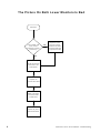
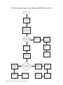
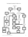
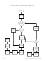
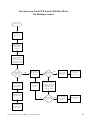
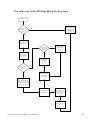
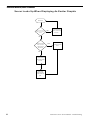
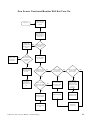
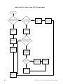
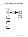
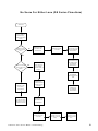
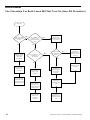
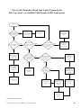
Introduction
The purpose of this troubleshooting guide is to provide fast solutions to problems that a bowling center may experience. Using this guide prior to contacting
Brunswick’s Customer Response Center will not only speed your troubleshooting efforts, but will give Brunswick’s technicians valuable information should
calling the Response Center be necessary.
Before attempting to troubleshoot any situation, obtain as much information
relating to the malfunction as possible. This information can be obtained from
bowlers, control desk operators or by simple observation. Make sure that the
information provided to you from other sources is accurate. Many times the
person providing the information will have a different perspective of the equipment than that of a mechanic or may use different terms to describe the situation.
This leads to misunderstanding as to what the defect is. Inaccurate or misinterpreted information will cause delays, add cost by replacing good parts and
eventually lead to frustration.
It is also important to not automatically assume that a board or cable is bad when
a malfunction occurs. Many times an error occurs because of improper operations, improper setup, or a onetime event that causes a failure. Cycling power
(turning power off, then on) will usually correct these situations.
If the failure seems to be caused by a bad circuit board, verify this by replacing
the suspected board with one that is known to be functional. If the replacement
board solves the problem, verify that the board removed is actually defective by
installing it in another unit. Many times, failures are caused by a bad connection
that is solved by replacing the board or by simply reseating it or checking it’s
connectors. Numerous circuit boards have been sent to Brunswick for repair
even though there was nothing wrong with them. Again, this leads to unnecessary maintenance costs for the center.
This guide contains flowcharts to help the mechanic quickly solve common
problems that may be encountered. It is assumed that the troubleshooter is
familiar with the components and terminology used in the Frameworx system
and the basic operation of a multimeter and cable testers. For additional information about these topics, consult the Scoring System Service Manual
(57-900351-000) or the instruction manual that was sent with the multimeter or
tester.
Frameworx Scorer Service Manual - Troubleshooting
1
Intentionally Blank
2
Frameworx Scorer Service Manual - Troubleshooting
Troubleshooting
Communications Problems to the Lanes
O n e Lan e P air is "O fflin e" At T he C o ntro l D esk
S tart H ere
P u t th e lan e
"O n Lin e" u s in g
th e X fu n c tion at
th e s c orer s tatu s
s c reen.
Is p ow er
p res en t at the L G P of
th e affec ted
L an es ?
NO
Y ES
R efer to th e
flow c hart "B oth
O verh ead m on itors
w ill not tu rn on
(S kyw orx/
T eam w orx)"
C h ec k th e fus es at
th e LG P for th e
affec ted lan es .
C yc le p ow er to the
P rim ary c on s ole or
L G P of th e affec ted
lan e p air
Y ES
Is this a
T eam w orx or
S kyw orx Ian e
NO
R ep lac e th e P ow er
S u pp ly in th e LG P
for th e affec ted
L an es
D id th e S c orer
c om e bac k on?
Y ES
NO
R efer to th e
F low c h art "T he
overh ead an d
low er m on itors w ill
n ot tu rn on
V erify that th e L ane
P air is N O T in
S tan d A lon e m od e.
(S ee M ain ten an c e
M enu )
V erify that th e left
lan e n u m b er is
c orrec t for the
s c orer (S ee
M ain ten anc e M en u )
V erify that th e
1 0 B as eT C ab le is
p lu g g ed in at th e
H u b an d at th e
LG P .
NO
Is th e H u b 's L in k L E D fo r th a t
la n e p a ir o n ?
(S e t th e H u b S w itc h to L N K )
Y ES
C h ec k th e c ab le
b etw een th e H u b
an d th e L G P .
R ep lac e th e L G P
E th ern et B oard .
Frameworx Scorer Service Manual - Troubleshooting
R es eat th e E thern et
b oard in s id e th e
LG P
C on n ec t the
1 0 B as eT C ab le to a
kn ow n w orkin g port
on the H ub .
3
A ll L a ne s A re "O fflin e " At T he C o n tro l D e sk
S tart H ere
P u t th e lan es
"O n Line" us in g
the X fu nc tion at
the s corer s tatus
s c reen .
V erify th at p ow er is
p resen t at all LG P s .
C h ec k the c able
b etw een th e C M S
C om p uter and th e
H u b.
C yc le P ow er to the
C M S C om pu ter
u sing th e H alts ys
c om m an d
R eplac e the C M S
E th ern et P C B .
(You m us t c on fig ure
the new P C B )
V erify th at the 5 0
O hm T erm inators
are prop erly
c onn ec ted at eac h
end of the H ub 's
c oaxial c ab le.
R es eat the C M S
E th ern et P C B to
ens u re a g ood
c onn ec tion .
A re an y lig hts "on" at th e
E th ern et H ub (s )?
R ec on figu re the
C M S E th ernet P C B
u sing th e
c onfigu ration
d is kette
NO
V erify th at the H u b
is plug ged in to a
w orking pow er
outlet
R eplac e the H ub /
H u b P ow er S u pp ly
YES
C ontac t B ru ns w ick's
C u stom er R es pon s e
C enter for as s is tan c e
w ith th e follow ing
p roced ures
R eboot all sc orers
b y cyclin g pow er to
the P rim ary c on sole
or LG P
4
C yc le P ow er to the
H u b(s )
NO
D o e s th e a c tivity lig h t o n th e H u b
fla s h w h e n a tte m p tin g to a c c e s s
a la n e fro m th e d e s k ?
YES
Frameworx Scorer Service Manual - Troubleshooting
Console Monitor/Video Problems
O ne Lo w er M o nitor W ill N ot Turn O n
S tart H ere
A re the LE D s on the
C ons ole C ontroller P C B
O n or F las hing?
NO
Is the problem
with the prim ary
c ons ole?
NO
C hec k for the
proper input voltage
to the S ec ondary
T ransform er
Y ES
Y ES
Y ES
Is there A pprox..
12V D C at J 6 of the
C ons ole C ontroller
PCB?
NO
Is the 12V D C relay
for the m onitor
energizing?
NO
C hec k T he cable
between the
C ons ole C ontroller
P C B and the relay
R eplace the R elay
C hec k the V oltage
input c able to the
A uxiliary
T ransform er
C hec k the Fus es
for the S ec ondary
T ransform er
Y ES
C hec k the LLA N
c able to the
C ons ole C ontroller
PCB
C hec k the M G ain
adjus tm ent for the
CRT
R eplac e the
C ons ole C ontroller
PCB
C hec k the video
c able between the
C ons ole V ideo P C B
and the V ideo
P roc es s or M odule
C hec k the 120V A C
c able between the
relay and the V ideo
P roc es s or M odule
C hec k the Fuses
for the A uxiliary
T ransform er
C hec k the wiring to
J7 of the C onsole
C ontroller P C B
R eplace the
C ons ole C ontroller
PCB
C hec k the 120V A C
c able between the
trans form er and the
relay
R eplac e the V ideo
P roc es s or M odule
Frameworx Scorer Service Manual - Troubleshooting
R eplace the
C ons ole V ideo P C B
R eplac e the C R T
5
B o th Low er M onitors W ill N o t Turn O n
A re th e L E D s on
th e C on s ole C on troller
P C B s on or flas h in g
S tart H ere
C h ec k for th e
p rop er inp u t voltage
to the trans form ers
in b oth c on s oles
NO
C h ec k th e fus es for
th e tran s form ers in
b oth c on s oles
Y ES
R ep lac e th e
C on s ole C on troller
PCB
C yc le p ow er to th e
p rim ary c on s ole.
L is ten c los ely to the
s ou n d c om in g from
th e hard d rive (H D )
D id you hear th e
H D s pin u p ? (D rive
LE D O n)
NO
C h ec k th e p ow er
c ab le to th e H D
C h ec k th e c ab les
from the
tran s form er to th e
C on s ole C on troller
PCB
M ake s u re th at th e
rib bon c ab le
b etw een th e I/O
P C B an d th e H D is
p lu g ged in c orrec tly
Y ES
C h ec k th e ribb on
c ab le b etw een th e
I/O P C B an d th e
HD
R ep lac e th e I/O
PCB
R eb oot th e P rim ary
C on s ole w ith th e
C M O S M ain ten an c e
b oard in s talled in th e
M otherb oard
R es eat all b oard s in
th e m oth erb oard to
verify p roper
c on n ec tion s
If th e R em ote V id eo
B oard is p res en t,
c h ec k th e ju m p er
s ettin g s for both
vid eo board s
6
Y ES
A fter the initial
"p ow er on " b eeps , d o th e
c on s oles b eep again after 3 0
- 1 8 0 s ec ond s ?
R ep lac e th e
C on s ole V ideo
B oard
R ep lac e th e H D
C h ec k th e
c on n ec tion s for th e
S IM M (s ) on th e
M otherb oard
C h ec k th e L LA N
c ab le b etw een th e
I/O P C B an d th e
C on s ole C on troller
PCB
NO
R ep lac e th e I/O
PCB
R ep lac e th e
M otherb oard
R ep lac e th e H D
Frameworx Scorer Service Manual - Troubleshooting
T h e P ictu re O n O n e L o w e r M o n ito r Is B a d
S tart H ere
Is the problem with
foc us , s c reen
brightnes s or im age
pos itioning?
Y ES
A djus t the s c reen
us ing the c ontrols
loc ated on the V ideo
P roc es s or P C B and
the A djus tm ent P C B .
NO
C hec k the c able from
the C ons ole V ideo
P C B to the V ideo
P roc es s or P C B
R es eat the C ons ole
V ideo P C B in the
m otherboard
R eplac e the V ideo
P roc es s or P C B
R eplac e the
C ons ole V ideo P C B
R eplac e the pic ture
tube
Frameworx Scorer Service Manual - Troubleshooting
7
Th e P ictu re O n B oth Lo w er M on itors Is B ad
S tart H ere
Is the problem with
foc us , s c reen
brightnes s or im age
pos itioning?
Y ES
A djus t the s c reen
us ing the c ontrols
loc ated on the V ideo
P roc es s or P C B s and
the A djus tm ent P C B s .
NO
R es eat the C ons ole
V ideo P C B in the
m otherboard
R eplac e the
C ons ole V ideo P C B
R eplac e the V ideo
P roc es s or P C B s
for both lanes
R eplac e the pic ture
tube for both lanes
8
Frameworx Scorer Service Manual - Troubleshooting
The O verhead s An d Low er M o nitors W ill N ot Turn O n
S tart H ere
C hec k for the
proper input voltage
to the prim ary
c ons ole
C yc le power tp the
prim ary c ons ole. Lis ten
c los ely to the s ound
c om ing from the hard
drive (H D ) or look at the
drive LE D
D id you hear the
H D s pin up? (D rive
LE D O n)
NO
C hec k the pow er
c able to the H D
M ake s ure that the
ribbon c able
between the I/O
P C B and the H D is
plugged in c orrec tly
Y ES
C hec k the ribbon
c able betw een the
I/O P C B and the
HD
R eplac e the I/O
PCB
R eboot the P rim ary
C ons ole w ith the
C M O S M aintenanc e
board ins talled in the
M otherboard
R es eat all boards in
the m otherboard to
verify proper
c onnec tions
C hec k the jum per
s ettings for both
video boards
Y ES
A fter the initial
"pow er on" beeps , do the
c ons oles beep again after 30
- 180 s ec onds ?
R eplac e the V ideo
B oards
Frameworx Scorer Service Manual - Troubleshooting
R eplac e the H D
NO
C hec k the
c onnec tions for the
S IM M (s ) on the
M otherboard
R eplac e the I/O
PCB
R eplac e the
M otherboard
R eplac e the H D
9
Console Input Problems
N o K eyb oard O p eration F or O n e L an e
S tart H ere
C ycle P ower to the
LG P
Y ES
Is this a
T eam worx
(S olution 3)
console?
NO
C ycle power to the
S econdary
C onsole, then
cycle power to the
P rim ary C onsole
D id the affected
console beep when power
was applied?
NO
C heck for A C
voltage at J 7 of the
C onsole C ontroller
PCB
Y ES
C heck for A C
voltage at J 7 of the
C onsole C ontroller
PCB
NO
D id both
consoles beep?
Y ES
Is the voltage
approx.
14V A C ?
C heck the LLA N
cable to the
C onsole C ontroller
PCB
Y ES
NO
NO
Is the problem
on the prim ary
console?
D oes the m onitor
on the affected console
turn on?
Y ES
NO
C heck the cable
from the keyboard
to C onsole
C ontroller P C B
Y ES
Is the voltage
approx.
14V A C ?
Y ES
NO
C heck for power
input to the
S econdary
T ransform er
C heck for proper
jum per settings on
the C onsole
C ontroller P C B
R eplace the
C onsole C ontroller
PCB
R eplace K eyboard
C heck for blown
fuses in the
T ransform er for
that console.
C heck the fuses for
the S econdary
T ransform er
R epair or replac e
the faulty power
cable.
10
Frameworx Scorer Service Manual - Troubleshooting
N o K eyb o ard O p eratio n F o r E ith er L an e
S tart H ere
C ycle power to the
LG P
C hec k for A C
voltage at the M ini
C ons ole outpu t of
the LG P
NO
Y ES
D id b oth
consoles beep ?
Is th is a
T eam worx
(S olution 3)
C ons ole?
NO
Y ES
C ycle power to the
second ary c onsole,
then cycle power to
the prim ary cons ole
D id the both
consoles beep when
power w as applied?
C hec k the LLA N
cable to the
C ons ole C ontroller
PCBs
NO
NO
C hec k for A C
voltage at J7 of the
C ons ole C ontroller
P C B at both
consoles
Y ES
Is th e voltage
app rox. 14 V A C ?
Y ES
C hec k the
connec tion s for the
I/O P C B :
R eplace the I/O
PCB
C hec k for A C
voltage at J7 of the
C ons ole C ontroller
P C B of the left
C ons ole
NO
D oes the m onitor
on the affec ted c onsole
turn on?
Y ES
C hec k the cab le
from the keyboards
to th e C ons ole
C ontroller P C B s for
both lan es
Is th e voltage
app rox. 14 V A C ?
C hec k power inpu t
and fu ses for the
second ary
transform er in the
LG P
Y ES
Is th e voltage
app rox.
14V A C ?
Y ES
NO
R eplace the
second ary
transform er in the
LG P
NO
C hec k for proper
ju m per settings on
the C onsole
C ontroller P C B
R eplace the
C ons ole C ontroller
PCBs
C hec k for blown
fuses in the
transform er for both
consoles .
R eplace both
keyboards
R epair or replace
the faulty power
cable(s ).
Frameworx Scorer Service Manual - Troubleshooting
11
N o T o u c h s c re e n O p e ra tio n F o r O n e L a n e
S tart H ere
C yc le p ow er to the
s ec on dary c ons ole,
th en c yc le pow er to
th e p rim ary c on s ole
D id th e affec ted
c ons ole beep w h en
p ow er w as app lied?
NO
Y ES
C alib rate th e
tou ch s c reen (S ee
M ain ten an c e M en u)
Y ES
C h ec k for A C
voltage at J 7 of the
C on s ole C on troller
P C B of th e c on s ole
Is any entry to
th e s c reen
p os s ib le?
NO
C h ec k th e L L A N
c ab le to th e C on s ole
C on troller P C B
R ep lac e th e
tou ch s c reen
Y ES
Is the voltage
ap prox.
1 4V A C ?
NO
C h ec k for prop er
ju m per settin g s on
th e C ons ole
C on troller P C B
R ep lac e th e
T ou c hs c reen
C on troller
(In terfac e)
C h ec k for blow n
fus es in th e
tran s form er for th e
c on s ole.
R ep lac e th e O p tion
PCB
R ep lac e th e
C on s ole C on troller
PCB
C h ec k th e jum p er
s ettin gs of th e
O p tion P C B
R ep lac e th e
T ran s form er
12
R ep air or rep lac e
th e fau lty p ow er
c ab le(s ).
Frameworx Scorer Service Manual - Troubleshooting
N o To uch screen O peratio n Fo r E ith er Lane
S tart H ere
C ycle power to the
secondary console,
then c ycle power to
the prim ary c ons ole
D id the affected
c ons oles beep w hen
power was app lied?
NO
YES
C alibrate the
touch sc reens (S ee
M ain ten anc e M enu )
YES
C heck for A C
voltag e at J 7 of the
C on sole C on troller
P C B s at both
cons oles
Is any entry to
the sc reen
poss ible?
NO
C heck the LL A N
cable to the C onsole
C on troller P C B s
R ep lace both
touch sc reens
YES
NO
C heck for p roper
jum per settings on
both C onsole
C on troller P C B s
R ep lace both
T ouc hs creen
C on trollers
(Interface)
Is the voltage
ap prox.
14 V A C ?
C heck for b lown
fus es in the
tran sform ers for the
both c ons oles .
R ep lace both
O ption P C B s
R ep lace both
C on sole C on troller
PCBs
Frameworx Scorer Service Manual - Troubleshooting
C heck the jum per
settings on both
O ption P C B
R ep air or replac e
the fau lty p ower
cable(s).
13
Audio Problems
The In tercom And VC R Audio W ill N ot W ork O n O ne Lane O r Lane P air
S tart H ere
D oes the problem
affec t both lanes of
the lane pair?
No te: U nless oth erw ise specified, all cab le co nn ectio ns reference
con necto rs th at are lo cated on C on sole Au dio PC Bs
NO
V erify th at th e
ju m p er s ettin g for
the C ons ole A udio
P C B of th e affec ted
c ons ole is c orrec t
C hec k the s peaker
and w iring to the
S peaker
Y ES
D is c onnec t the audio
c ables from c onnec tions
J 2 and J 3 on the
C ons ole A udio P C B of
the prim ary c ons ole w ith
the problem
D oes th e A udio
w ork for this
s c orer?
Y ES
Y ES
R ec onnec t the
c able to J 3 of the
audio P C B
D oes th e au d io
s till fun c tion ?
R eplac e the A udio
P C B in the prim ary
c on s ole
NO
NO
C hec k the c able
b etw een J 3 of th e
prim ary c ons ole
and J 1 of the
s ec ondary c ons ole
R eplac e the A u d io
P C B in th e
s ec ondary c on s ole
Y ES
NO
C hec k the c able
from J 1 to J 3 of the
prior prim ary
c ons ole's audio
PCB.
Is th e p rob lem w ith
the prim ary
c on s ole?
R eplac e the
C ons ole C on troller
P C B in th e
s ec ondary c on s ole
R ec onnec t J 2 of the
audio P C B . D is c onnec t
th e c ab les from J 2 an d
J 3 at the next prim ary
c on s ole's au d io P C B
R eplac e the audio
T erm inator (If
pres ent)
Y ES
D oes th e au d io
fu n c tion p rop erly?
NO
C hec k the c able
betw een J 1 and the
prior P rim ary
C ons ole
R eplac e the A u d io
P C B in th e prim ary
c on s ole
R eplac e the
C ons ole C on troller
P C B in th e prim ary
c on s ole
14
Frameworx Scorer Service Manual - Troubleshooting
T he Intercom An d V C R Au d io W ill N o t W o rk
O n M u ltip le L an es
S tart H ere
C yc le power to the
C M S A /V box
C yc le power to the
C M S C om pu ter
us ing the H alts ys
C om m an d
D isc on nect the audio
c ab les from connec tions
J 2 and J3 on th e
C ons ole A u dio P C B of
th e first prim ary cons ole
c on nec ted to the A /V b ox
D oes th e A ud io
work for th is
s corer?
YES
R econn ec t the
c ab le to J3 of the
audio P C B
D oes th e aud io
s till func tion ?
C h ec k the c ab le
betw een J 3 and J1
of the s ec on dary
c on sole
R eplac e the A udio
P C B in the
s ec on dary cons ole
C h ec k the c ab le to
J 1 of the A ud io
PCB
R eplac e the A udio
PCB
YES
NO
C h ec k the C able
F rom th e A /V B ox
to J 1 of the first
prim ary cons ole
NO
R econn ec t J 2 of th e
audio P C B . D is conn ec t
th e c ab les from J2 and
J 3 at th e n ext prim ary
c on sole's aud io P C B
R eplac e the audio
T erm in ator (If
present)
R eplac e the A udio
P C B in the A /V B ox
YES
D oes th e aud io
fun ction p roperly?
NO
R eplac e the A udio
P C B in the 1s t
prim ary cons ole
Frameworx Scorer Service Manual - Troubleshooting
15
T he In terco m W ill N o t W ork O n O n e L an e O r L an e P air
S tart H ere
D oes the V C R
au dio w ork on the
lane(s )?
NO
U s e the F low c hart
titled "T he Interc om
A nd V C R A ud io W ill
N ot W ork O n O ne
Lane O r Lane P air"
Y ES
D oes the p roblem
affec t both lanes of
the lan e pair?
NO
C hec k the w iring to
the M ic rophone
NO
Is the p roblem w ith
the prim ary
c ons ole?
Y ES
Y ES
D is c onnec t the audio
c ables from c onnec tion s
J 2 and J 3 on the
C ons ole A u dio P C B of
the prim ary c ons ole w ith
the problem
D oes the Interc om
w ork for this
s c orer?
Y ES
R ec onnec t the
c able to J 3 of the
au dio P C B
R eplac e the
C ons ole C on troller
P C B in the
s ec ondary c ons ole
R ec onnec t J 2 of the
au dio P C B . D is c onnec t
the c ables from J 2 and
J 3 at th e next prim ary
c ons ole's audio P C B
R eplac e the audio
T erm inator (If
pres ent)
Y ES
R eplac e the A u dio
P C B in the prim ary
c ons ole
R eplac e the A u dio
P C B in the
s ec ondary c ons ole
Y ES
NO
C hec k the c able
from J 1 to J 3 of th e
prior prim ary
c ons ole's audio
PCB.
NO
D oes the audio
s till fu nc tion ?
C hec k the c able
betw een J 3 of the
prim ary c ons ole
au dio P C B and J 1
of the s ec ondary
c ons ole audio P C B
D oes the audio
fu nc tion properly?
NO
C hec k the c able
betw een J 1 and the
prior P rim ary
C ons ole
R eplac e the A u dio
P C B in the prim ary
c ons ole
R eplac e the
C ons ole C on troller
P C B in the prim ary
c ons ole
16
Frameworx Scorer Service Manual - Troubleshooting
T h e In terco m A u d io W ill N o t W o rk O n A n y L an e
S tart H ere
D oes the V C R
audio w ork on the
Lanes ?
U se the flow c hart
titled "T he Interc om
A n d V C R A u dio
W ill N ot W ork O n
A n y L ane
NO
Y ES
C yc le pow er to the
C M S A /V box
C an the bow ler
hear you at the
c ons ole?
C yc le pow er to the
C M S C om puter
us ing the H alts ys
C om m and
NO
C hec k for a bad
hands et H ook
S w itc h
Y ES
C hec k the V olum e
Level on the
H ands et
D oes the Interc om
w ork in one
direc tion?
Y ES
NO
C hec k the C ables
from the h an ds et to
th e A /V B ox
V erify that the H andset
c abling is plugged into
the proper c onnec tors at
th e bac k of the A /V B ox
R ep lace th e
H ands et
C hec k the
c onnec tions ins ide
the c onnec tor for
the Lane A udio O ut
at th e A /V B ox
R ep lace th e A /V
B ox
Frameworx Scorer Service Manual - Troubleshooting
17
Overhead Monitor/Video Problems
S corer Locks U p W hen D isplaying An E xciter G raphic
S tart H ere
Is th is th e firs t tim e th e
p ro b le m h a s o c c u re d fo r
th is la n e ?
Y ES
C yc le p ow er to th e
P rim ary C on s ole or
th e L G P
NO
D oes th e s c orer
loc k up on the
s am e graphic
eac h tim e?
Y ES
R eplac e the H ard
D rive
NO
R es eat the R em ote
V ideo board ins ide
th e L G P .
R ep lac e th e
R em ote V id eo
board in s ide th e
LG P .
18
Frameworx Scorer Service Manual - Troubleshooting
O ne S corer O verhead M on ito r W ill N ot Tu rn O n
C ycle power to the
LG P or P rim ary
C onsole
S tart H ere
S wap the V ideo
c ables at the top of
the overheads for
the lane pair.
S wap the video
cable for the
overhead at the
R em ote V ideo
P C B.
Y ES
D oes the problem
m ove to the other
m onitor?
NO
C heck the video
c able for a bad
c onnec tion or
broken wire.
NO
D oes the
problem m ove back
to the original
m onitor?
C hec k the fus es in
the O verhead
Y ES
R es eat the R em ote
V ideo board inside
the LG P .
D oes the relay
ins ide the overhead
m onitor energize?
NO
Y ES
R eplac e the
R em ote V ideo
board inside the
LG P .
Is there 120V A C at
both the input A ND
output of the relay?
Is there 12V D C at
J4 of the V ideo
R ec eiver P C B ?
Y ES
NO
NO
Is there A C V oltage at
J2 of the V ideo
R ec eiver P C B ?
NO
Y ES
C hec k the wires to
the relay for good
c onnec tions .
C hec k the c able
from the top of the
m onitor to J1 of the
V ideo R ec eiver P C B
for good
c onnec tions .
R eplac e the R elay
R eplac e the V ideo
R eceiver P C B
Y ES
R eplac e the V ideo
P rocessor M odule.
R eplac e the P ic ture
T ube.
Frameworx Scorer Service Manual - Troubleshooting
R eplace the
T ransform er
19
B o th O verh ead M o n ito rs W ill N o t T u rn O n (P o w erw o rx / T o u ch w o rx)
S tart H ere
C hec k if the
m on itors are in T V
m od e
C hec k the fuses for
both overheads
C hec k the input
voltage s etup for
both overheads
R eseat the R em ote
V ideo board insid e
the LG P .
R eplace the
R em ote V ideo
board inside th e
LG P .
C hec k the video
cables for bad
connections or
broken wires.
20
Frameworx Scorer Service Manual - Troubleshooting
B o th O verh ead M o n ito rs W ill N o t T u rn O n (S kyw o rx/T eam w o rx)
S tart H ere
C ycle power to the
prim ary con sole. L is ten
clos ely to the sound
com ing from th e hard
drive (H D ) or look at the
drive LE D
D id you hear the
H D spin up ? (D rive
LE D on)
NO
C hec k the p ower
C able to the H D
M ake sure that th e
ribb on c able
between the I/O
P C B and the H D is
plugged in correc tly
Y ES
A fter the
initial "power on"
beeps , do th e c ons oles
beep again after
30 - 18 0
seconds?
NO
C ycle power to the
P rim ary C ons ole with
the C M O S
M aintenan ce b oard
installed in the
M otherboard
R eplac e th e I/O
PCB
Y ES
R eplac e th e H D
C hec k the ribbon
cable between the
I/O P C B and th e
HD
C hec k the fus es in
both overheads
R es eat the all
boards in the
m otherboard to
verify prop er
connections
C hec k the
connections for the
S IM M (s) on the
M otherboard
R eplac e th e I/O
PCB
R eplac e th e H D
C hec k the overhead
vid eo c able b etween
the R em ote V ideo
B oard an d the
overhead m onitors
R eplac e th e
M otherboard
R eplac e th e
R em ote V id eo
B oard
Frameworx Scorer Service Manual - Troubleshooting
21
O n e TV -O nly M onitor W ill N ot Turn O n
S tart H ere
C yc le p ow er to the
P rim ary C on sole or
LG P
NO
D oes th e P ins etter
turn on and off
c orrec tly?
NO
Is th e TV O n ly B o a rd p re s e n t
w h e n vie w in g d ia g n o s tic 's
"Te s t 4 8 5 D e vic e s " ?
YES
YES
C hec k the fu ses in
the overh ead and
pow er to the
overhead
C hec k the fu ses in
the O verhead
C hec k L LA N c ab le
betw een th e LG P
I/O P C B A n d T he
P ins etter In terfac e.
C hec k the LL A N
c ab le at th e top of
the m on itor
R eplac e the L G P
I/O P C B .
C hec k the LL A N
c ab le b etw een the
P ins etter In terfac e
and the O verh ead.
C hec k the vid eo
c ab le at th e top of
the O verhead
D oes the relay
in side the overhead
m onitor en ergize?
NO
YES
C hec k the LL A N
c ab le ins ide th e
overhead betw een
the top of the m on itor
and the T V -O n ly P C B
Is th ere 12 V D C at
J 3 of th e T V O n ly
PCB?
NO
Is there A C V oltag e at
J 2 of th e T V O n ly
PCB?
NO
YES
YES
Is there 1 20 V A C
at b oth the inp ut
AND ou tput of
the relay?
NO
C hec k the w ires to
the relay for g ood
c on nec tion s.
C hec k the cab le
from the top of th e
m onitor to J 1 of the
T V O n ly P C B for
good c on nections .
YES
R eplac e the T V
O n ly P C B
R eplac e the V ideo
P roc ess or M od ule.
R eplac e the P ic tu re
T ube.
22
R eplac e the R elay
R eplac e the T V
O n ly P C B
R eplac e the
T rans form er
Frameworx Scorer Service Manual - Troubleshooting
T he P ictu re O n O n e S co rer O ve rh ead M o nito r Is B a d
S tart H ere
S w ap the V ideo
cable at the top of
the overheads for
the lane pair.
S w ap the video
cable for the
overhead at the
R em ote V ideo
PC B.
YES
D o e s th e p ro b le m m o ve
to th e o th e r m o n ito r?
NO
C heck the video
cable for a bad
connection or
broken wire.
NO
D o e s th e p ro b le m m o ve
b a c k to th e o rig in a l
m o n ito r?
YES
R es eat the R em ote
V ideo board inside
the LG P .
Is the problem w ith
focus, s creen
brightnes s or im age
pos itioning?
NO
Adjust the s creen
using the
P inc ushion controls
on the V ideo
P rocessor M odule
YES
R eplace the
R em ote V ideo
board inside the
LG P .
Frameworx Scorer Service Manual - Troubleshooting
Adjust the s creen
using the controls
located on the V ideo
P rocessor P C B and
the A djustm ent P C B .
C heck the w ires to
the V ideo R ec eiver
board for good
connections.
R eplace the V ideo
P rocessor P C B .
C heck the V ideo
cable from the V ideo
R ec eiver P C B to the
V ideo P rocess or for
good c onnec tions
R eplace the picture
tube
C heck the V ideo
C onnector at the
top of the overhead.
23
The P icture O n B o th S corer O verhead M onito rs Is B ad
S tart H ere
C heck the V ideo
T erm inator on the
R em ote V ideo P C B
at the las t lane
Y ES
Is the problem
for th e T V /V C R
pic ture only?
Note
NO
Pro blem s with the g lobal v ideo
cable and v ideo term inato r m ay
effect m ultiple lanes.
C heck the G lobal
V ideo C able at the
R em ote V ideo P C B
on the affec ted lane
pair
Is th e problem with
foc us , s c reen
brightness or im age
pos itioning?
NO
R es eat the R em ote
V ideo board inside
th e LG P .
Y ES
R eplac e the
R em ote V ideo P C B
A djust the sc reen
using the c ontrols
loc ated on the V id eo
P roc es sor P C B and
the A djus tm ent P C B .
R ep lac e th e
R em ote V id eo
board ins ide the
LG P .
C h eck the c ables
from the R em ote
V id eo P C B to b oth
overhead m onitors .
R ep lac e both V ideo
R ec eiver P C B s
R ep lac e both V ideo
P roc es sor P C B s
R ep lac e both
pic ture tubes
24
Frameworx Scorer Service Manual - Troubleshooting
T h e P ictu re O n O n e O r M u ltip le T V -O n ly O verh ead M o nito r(s) Is B ad
S tart H ere
D oes the problem
oc c ur w ith both tape
and T V
s ig nals ?
NO
D oes the
problem effec t only
one m on itor?
NO
D oes the P roblem
oc c ur w ith jus t th e
T ape s ig nal?
NO
C hec k the inpu t
s ignal from the
antenn a, c able
c om pany or s atelite
rec eiver
Y ES
Y ES
Y ES
Is there a dark line on
the s c reen or does the
s c reen roll?
Y ES
A d jus t th e H or.
c ontrol in th e C M S
A /V box.
C lean/replac e the
VCR
NO
Is th e problem w ith
foc u s , s c reen
brightnes s or im ag e
pos itionin g?
NO
C hec k the video
c able at the top of
the overh ead for a
bad c onnec tion.
Y ES
A d jus t th e s c reen
us ing the c on trols
loc ated on the V ideo
P roc es s or P C B and
the A d jus tm ent P C B .
C hec k the V ideo
term in ator at the
las t T V -O nly
M on itor
C hec k the G lobal
A u dio c ab le
c onn ec tions at
eac h T V -O nly
M on itor
C hec k the video
c onn ec tion at the
prior T V -O nly
M on itor
C hange the C M S
A /V B ox
R ep lac e the V ideo
P roc es s or P C B .
R ep lac e the pic ture
tube
C hec k the w ires to
the T V -O nly b oard
for good
c onn ec tions .
C hec k the V ideo
c able from the
T V -O nly P C B to the
V id eo P roc es s or for
good c on nec tion s
R ep lac e the
T V -O nly P C B
Frameworx Scorer Service Manual - Troubleshooting
25
Scoring Prblems
M is-sco ring O n O ne Lane (C C D S canners)
S tart H ere
C heck for proper
operation of the
pins etter
Is the m is -score by
one or two pins only?
Y ES
C heck the pin
conditions for that
lane.
NO
P lug the sc anner
tester into the tes ter
connector and veiw
the inform ation on the
"N orm al" screen
C heck the 1st-2nd
ball light adjustm ent
NO
Is the
1st /2nd ball
indic ation c orrec t on
the s cann er tester?
C heck for s hiney or
oily spots on the pit
curtain
C heck for irregular
bends in the pit
curtain
Y ES
Note
If a 2nd infrared ball detector for optional equipm ent
such as autom atic triggering is present, verify that it
is not interfering with the C C D ball detector.
C heck the ball
detec tor align m ent.
C heck the
adju stm ent on the
adjacent lanes as
w ell.
NO
D oes the B all detector
indic ate w hen th e ball
detec t beam is blocked?
Y ES
R eplac e the ball
detec tor
A djust the take data
and th e 0 degree
(A M F - S w eep up)
sw itches
C alibrate the C C D
C am era u sing the
sc anner tester
26
C heck the wirin g
from the pins etter
to the C C D D ata
P roc ess or B ox.
R eplac e the T ake
D ata R elay in A -2
P insetters (If
equipped)
Frameworx Scorer Service Manual - Troubleshooting
M is-scoring O n B oth Lanes (C C D S canner)
S tart H ere
D oes the S c an n er
T es ter's "N orm al" s c reen
s how the proper s c ore?
Y ES
V erify the s w itc h
s etup in the
P in setter In terfac e
B ox
R eplac e the
P insetter C ontroller
P C B / P ins etter
Interfac e B ox
NO
C hec k the V ideo
C able B etw een the
C am era and the
C C D D ata
P roc es s or P C B
NO
V erify th at th e s c orer
c ons ole is c onfigured
for the proper
pins etter type
(M ain ten anc e M enu D iagnos tic s )
D o the
alignm ent s c reen s
dis play live video
properly?
Y ES
H as there been an y
m aintenanc e perform ed
on both pinsetters ?
Y ES
C hec k th e T ake
D ata and 0 degree
(A M F - S w eep u p )
s w itc h adjus tm ents
on both pinsetters
NO
V erify that th e
s w itc hes on the
C C D D ata
P roc es s or P C B are
s et properly.
C hec k for s h iny or
oily s p ots on th e p it
c urtain on both
m ac h in es
R es et the s c anner
c alibration. (S ee
D IP s w itc hes 4,5,6)
C alibrate th e
c am era w ith the
tes ter
D o you have a
B runsw ic k A or A 2
pins etter?
NO
Frameworx Scorer Service Manual - Troubleshooting
Y ES
R eplac e the A M F
Interfac e P C B
R eplac e the C C D
C am era an d/or the
C C D D ata
P roc es s or B ox
27
N o Sco re F o r O n e Lan e (C C D S cann ers)
S tart H ere
Is th e sc ann er receivin g a
ball detec t s ign al? (S ee
"N orm al" s creen on tes ter)
Y ES
NO
V erify the s w itc h
s etup in th e
P ins etter In terface
B ox
R ep lac e th e
P ins etter C on troller
P C B / P ins etter
In terfac e B ox
NO
C yc le the P ins etter
A d ju s t th e B all
D etec tor
Y ES
C heck the w irin g to
th e B all D etector
Y ES
D oes a s core for th e lan e
app ear on th e "N orm al"
s creen of th e tester?
D o the T ake D ata and the
0 degree sw itc h es w ork
properly? (S ee "N orm al"
S c reen of tes ter)
NO
R ep lac e th e B all
D etec tor
C heck the T ake
D ata an d 0 degree
(A M F - S w eep u p)
s w itch adjus tm ents
on the pin setter
D o you h ave
B run sw ic k A -2 or A
P ins etter?
Y ES
C heck the
c on nec tions at th e
N ew P in S olenoid
M olex conn ector
R ep lac e th e T ake
D ata an d/or the 0
deg ree s witch (es )
NO
C heck the w irin g at
th e A M F Interfac e
PCB
R ep lac e th e C C D
D ata P roc es s or
B ox
28
Frameworx Scorer Service Manual - Troubleshooting
N o S c o re F or E ithe r L an e (C C D S c a nn e r)
S tart H ere
D oes th e
s c an n er have
p ow er
YES
D oes a s c ore for the lan e
app ear on the "N orm al"
s c reen of th e tes ter?
P erform a "C h ec k
4 85 D evic es "
(M ainten an c e M enu
- D iag n os tic s )
YES
NO
NO
D oes th e P in s etter
Interfac e B ox have
p ow er?
YES
C h eck th e fus e
in s id e th e C C D
D ata P roc es sor
B ox
C h eck th e C loc k
C ab le B etw een the
C am era an d the
C C D D ata
P roc es s or P C B
NO
C h eck th e W iring
B etw een th e
P ins etter In terfac e
B ox A n d th e C C D
D ata P roc es sor
B ox
C h eck th e c ab le
b etw een th e B all
D etectors and the
C C D D ata
P roc es s or B ox
R es et th e 2 8V A C
B reaker at the
S ec on dary
T ran sform er
R ep lace the C C D
D ata P roc es sor
B ox
C h eck th e T ake
D ata an d 0 deg ree
(A M F - S w eep up )
s w itc h ad ju s tm ents
on b oth pins etters
C h eck th e w irin g
from the s econ dary
tran sform er to the
P ins etter In terfac e
R ep lace the
C am era
YES
Is th e P in s etter
Interfac e p res ent?
YES
NO
D oes th e S c ann er
V ers ion m atc h
thos e for ad jac en t
lan es?
R ep lace the
P ins etter C ontroller
PCB
R ep lace the
tran sform er in the
P ins etter In terfac e
B ox
NO
YES
C h eck th e c ab lin g
b etw een th e C C D
D ata P roc es sor b ox
and the P ins etter
Interfac e B ox
V erify th at th e
s w itc h es on th e
P ins etter C ontroller
P C B are s et
p roperly
D o you h ave
B run s w ick A -2 or A
P ins etter?
R ep lace the L G P
I/O P C B
NO
C h eck th e w irin g at
the A M F Interface
PCB
Frameworx Scorer Service Manual - Troubleshooting
C h eck th e L LA N
B etw een th e
P ins etter In terfac e
B ox an d th e L G P
I/O P C B
29
M is-S core O n B o th L anes (G S S eries P in setters)
S tart H ere
D oes the
ins tallation have a
P insetter Interfac e
B ox?
NO
C hec k the LLA N
C able B etween the
I/O P C B and the
G S C onsolidated
E lectric al box
R eplace the
C ons olidated
E lectric al B ox C P U
PC B
Y ES
C hec k the D IP
switc h s etting on
the P ins etter
C ontroller P C B (If
P resent)
R eplace both I/O
P C B s in the
C ons olidated
E lectric al B ox
R eplace the
P insetter C ontroller
P C B / P insetter
Interfac e B ox
R eplace the LG P
I/O P C B
30
Frameworx Scorer Service Manual - Troubleshooting
N o S c o re F o r E ith e r L a n e (G S S e ries P in s e tters)
S tart H ere
V erify that the
s c orer is NOT in
m anual sc oring
(S ee m aintenanc e
m enu)
D oes the
ins tallation have a
P ins etter Interfac e
B ox?
NO
R es eat T he LG P
I/O P C B in the
m otherboard
R eplac e the LG P
I/O P C B
C hec k the s etup of
the s w itc hes in the
G S C ons olidated
E lec trical B ox
Y ES
D oes the P insetter
Interfac e B ox have
pow er?
Y ES
C hec k the LLA N
C able B etw een the
I/O P C B and the
C ons olidated
E lec trical box
C hec k the D IP
s w itc h s etting on
the P ins etter
C ontroller P C B (If
P resent)
R eplac e the
C ons olidated
E lec trical B ox C P U
PCB
NO
R es et the 28V A C
B reaker at the
S ec ondary
T rans form er
C hec k the w iring
from the s ec ondary
trans form er to the
P ins etter Interfac e
C hec k the LLA N
B etw een the
P ins etter Interfac e
B ox and the LG P
I/O P C B
R eplac e both I/O
P C B s in the
C ons olidated
E lec trical B ox
R es eat T he LG P
I/O P C B in the
m otherboard
R eplac e the LG P
I/O P C B
Frameworx Scorer Service Manual - Troubleshooting
R eplac e the
P ins etter C ontroller
P C B (G S C ontroller
PCB)
R eplac e the
trans form er in the
P ins etter Interfac e
B ox
31
Pinsetter Problems
T h e P in se tters F o r B o th L a n e s W ill N o t T u rn O n (N o n G S P in se tters)
S tart H ere
D oes the P ins etter
Interfac e B ox have
pow er?
NO
R es et the 28V A C
B reaker at the
S ec ondary
T rans form er
Y ES
D o the P insetters turn on
w hen us ing the
M ec hanic O verride
s w itc h
Y ES
P erform a "C hec k
485 D evic es "
(M aintenanc e M enu
- D iagnos tic s )
NO
A re you able to turn the
pins etters on at
the m ac hine?
Y ES
Is the P insetter
Interfac e lis ted as
pres ent?
NO
C hec k the LLA N
B etw een the
P ins etter Interfac e
B ox and the LG P
I/O P C B
Y ES
NO
C hec k the fuses for
the S ec ondary
T rans form er
C hec k the w iring
from the S econdary
T rans form er to the
P ins etter Interfac e
C hec k the M ain
pow er to both
P ins etters
V erify that all the
pow er interlock
s w itc hes on the
pins etters are in the
proper pos ition
C hec k the pow er
fus es for the
pins etter
(If P res ent)
32
C hec k the w iring
betw een the
pins etter interfac e
box and both
pins etters
R eplac e the LG P
I/O P C B
R eplac e the
P ins etter C ontroller
PCB
R eplac e the
trans form er in the
P ins etter Interfac e
B ox
Frameworx Scorer Service Manual - Troubleshooting
Th e P insetters For B oth L anes W ill N ot T urn O n (G S P insetters)
S tart H ere
Is a P ins etter
Interfac e ins talled on
the lane pair?
C hec k the C om line
D is c onnec t s w itc h
on the G am es etter
or C ons olidated
B ox
NO
P erform a "C hec k
485 D evic es "
(M aintenanc e M enu
- D iagnos tic s )
Is the G S
P ins etter pres ent
R eplac e the LG P
I/O P C B
Y ES
Y ES
D oes the Interfac e box
have a M ec hanic
override s witc h?
Y ES
D oes the P ins etter
Interfac e B ox have
pow er?
NO
NO
C hec k the C om line
D is c onnec t s w itc h
on the G am es etter
or C ons olidated
B ox
V erify that all the
pow er s w itc hes for
the pins etters are in
the proper pos ition
C hec k the LLA N to
the G S
C ons olidated
E lec tric al B ox
R eplac e the
C ons olidated
E lec tric al B ox C P U
PCB
C hec k the s etup
s w itc hes on the C P U
board in the
C ons olidated
E lec tric al B ox for
proper s etup
Y ES
NO
R es et the 28V A C
B reaker at the
S ec ondary
T rans form er
D o the P ins etters turn on
w hen us ing the
M ec hanic O verride
s w itc h
Y ES
P erform a "C hec k
485 D evic es "
(M aintenanc e M enu
- D iagnos tic s )
R eplac e both
C ons olidated
E lec tric al B ox
I/O P C B s
NO
C hec k the w iring
from the s ec ondary
trans form er to the
P ins etter Interfac e
Is the P ins etter
Interfac e lis ted as
pres ent?
NO
NO
Y ES
D o the pins etters turn on
w hen us ing the pins etter's
diagnos tic s m ode?
C hec k the LLA N
B etween the
P ins etter Interfac e
B ox and the LG P
I/O P C B
Y ES
C hec k the M ain
pow er to both
P ins etters
NO
D oes the Interfac e box
have a M ec hanic
override s witc h?
R eplac e the LG P
I/O P C B
Y ES
V erify that all the
pow er s w itc hes for
the pins etters are in
the proper pos ition
C hec k the w iring
between the
pins etter interfac e
box and both
pins etters
C hec k the pow er
fus es for the
pins etter (If
P res ent)
Frameworx Scorer Service Manual - Troubleshooting
R eplac e the
C ontroller P C B
(G S C ontroller
PCB)
R eplac e the
trans form er in the
P ins etter Interfac e
box
33
T he P insetter F or O ne L an e W ill N o t T urn O n (All P in setters)
S tart H ere
Is a P ins etter
Interfac e ins talled on
the lane pair?
NO
V erify that all the
power s witches for
the pins etter are in
the proper pos ition
C heck for power to
the pinsetter
C hec k the c able
from the
C ons olidated
E lec tric al B ox to the
P insetter
Y ES
D oes the P ins etter turn
on when using the
M echanic O verride
switch
R eplace the I/O
P C B in the
C ons olidated
E lec tric al B ox
Y ES
R eplac e the C P U
P C B in the
C ons olidated
E lec tric al B ox
NO OR
D O N 'T H A V E
S W IT C H E S
Y ES
D oes the pins etter turn on
at the m ac hine?
NO
C heck the M ain
power to both
P ins etters
V erify that all the
power s witches for
the pinsetter are in
the proper position
C heck the power
fuses for the
pins etter (If
P res ent)
34
C hec k the wiring
between the
pins etter interfac e
box and the
pins etter
R eplace the
P ins etter C ontroller
P C B (G S C ontroller
PCB)
R eplace the
transform er in the
P ins etter Interfac e
box
Frameworx Scorer Service Manual - Troubleshooting
T he A, A2 P insette r D o es N o t C yc le P rop erly fo r
N o T ap, F ou l, o r 3rd B all 10th F ram e (C C D S c ann ers)
S tart H ere
Is the problem
w ith jus t the foul
c ycle?
Y ES
C heck the C abling
From the Foul U nit
to the C C D D ata
P roc es sor P C B
R eplac e the Foul
U nit
R eplac e the C C D
D ata P roc ess or
B ox
NO
Is there a problem on
both lanes?
Y ES
NO
Y ES
C heck the D IP
S w itc h s ettings on
the C C D D ata
P roc es sor P C B
D oes the pinsetter
s weep all pins for foul
and N o tap cyc les
Y ES
NO
C heck T he D IP
S w itc hes O n the
C C D D ata
P roc es sor P C B
NO
D oes the pinsetter
go to s ec ond ball after
a foul or 3rd
ball cyc le?
NO
Y ES
V erify the settings
of the sw itches in
the P ins etter
Interfac e B ox
D oes the pinsetter
go to s ec ond ball after
a foul or 3rd
ball cyc le?
C heck / replac e the
c ycle link on the
pins etter
C heck the
c onnection at the
N P S M olex
c onnector
NO
D oes the LE D on the
relay board in the
N P S light?
Y ES
D oes the
S olenoid
energize?
C heck the c able
betw een the C C D
D ata P roc ess or box
and the N P S
NO
Y ES
R eplac e the C C D
D ata P roc ess or
B ox
A djust the N ew P in
S olenoid
C heck the 120V A C
pow er from the
pins etter to the
s olenoid
R eplac e the N P S
R elay P C B
R eplac e the
S olenoid
NOTE: NPS - NEW PINS SOLENOID
Frameworx Scorer Service Manual - Troubleshooting
35
The AM F Pinspotter D oes N ot C ycle Properly for
N o Tap, Foul, or 3rd B all 10th Fram e (C CD Scanners)
S tart H ere
Is the problem
w ith jus t the foul
cyc le?
Y ES
C heck the cabling
from the P inspotter
to the C C D D ata
P roc es sor P C B
R eplac e the Foul
U nit
NO
Is there a problem on
both lanes ?
Y ES
C heck the D IP
S witch settings on
the C C D D ata
P roc es sor P C B
V erify the s ettings
of the s witches in
the P insetter
Interfac e Box
NO
D oes the LE D on the
N ew P in relay board
light?
NO
C heck the
connection from the
C C D D ata P roces sor
B ox to the A M F
Interfac e PC B
Y ES
C heck the wiring
from the N ew P in
R elay to the
M ec hanic's reset
sw itc h
C heck the wiring
from the A M F
Interfac e P C B to
the affected
pins potter
R eplac e the N ew
P in R elay P C B
R eplac e the C C D
D ata P rocess or
B ox
36
Frameworx Scorer Service Manual - Troubleshooting
Glossary of Terms
10Base2 - The 50 ohm coaxial used in an Ethernet network. This cable is used to wire the office computer to the
hubs located on the curtain wall.
10BaseT - A cable that consists of two wires twisted around one another to form what is referred to as a twisted
pair. This is the type of cable that attaches the LGP to the Ethernet hubs.
Scorer Monitor - A monitor that is used to display the Scorer Console video. It can also display VCR video if
needed.
A/P - Automatic Pinsetter.
Audio - Electronic name for sound.
Ball Detector - An optical device that sends a signal to the scanner or pinsensor to start the scoring process whenever is senses the delivery of a ball.
Bowler Entry Station - The keyboard pedestal used in Teamworx (Solution 3) that allows the bowler to enter all
the information and selections as a Full scorer console but does not have the lower monitors.
CCD (Capacitor Charged Device) - A device that is kept in a constant state of electrical charge. When an outside
force stimulates the device, i.e. light, electrical energy is released.
CMOS (Complementary Metal Oxide Semiconductor) chip - A type of memory chip that retains its data when
power is turned off as long as it retains a trickle of power from a battery.
CMOS Maintenance Board - A circuit board that automatically sets up the LGP Motherboard to be compatible
with the hard drive installed in the LGP.
Coaxial Cable - A 2-Conductor cable consisting of a single center wire surrounded by a tubular shield. Most
coaxial cables use braided metal as the shield.
Console Video PCB - A circuit board located in the LGP that controls the video going to the lower monitors.
CPU (central processing unit) - A chip or circuit board that is the “brain” of the unit it resides in. The element that
does the actual adding and subtracting of 0s and 1s and the manipulation and moving of data that is essential to
computing. It is responsible for processing and logical decision making.
CRT (Cathode Ray Tube) - A video monitor or picture tube of a display.
DC (direct current) - Rectified AC or battery voltage. A type of current that is steady and free from all fluctuation.
Deflection Coil - An electrical coil that directs the electrons generated inside a CRT to a particular location on the
screen.
Frameworx Scorer Service Manual - Troubleshooting
37
Disk - A circular metal platter or Mylar diskette with magnetic material on both sides that stores programs and data.
Disks are rotated continuously so that read/write heads mounted on movable or fixed arms can read/write heads
mounted on movable or fixed arms can read or write programs or data to and from the disk. See also floppy disk,
hard disk.
Disk Drive - The motor that actually rotates the disk, plus the read/write heads and associated mechanisms, usually
in a mountable housing. Sometimes used synonymously to mean the entire disk subsystem.
Diskette - See floppy disk.
Download - To receive information from another modem and computer over the telephone lines. It is the opposite of
upload.
DRAM (dynamic random-access memory) - The most commonly used type of memory, found on video boards as
well as on PC system boards. DRAM is usually slower than VRAM (video random-access memory) since it has only
a single access pathway.
Error - A computer generated message indicating a failure during operation.
Ethernet - A communication protocol used by a group of computers to share information and transfer information to
one another.
Extractor - A tool used to remove a terminal from its housing.
File - A collection of related records treated as a unit. In a computer system, a file can exist on magnetic tape, disk,
or as an accumulation of information in system memory. A file can contain data, programs, or both.
Floppy Disk - A removable, rotating, flexible magnetic storage disk. Floppy disks come in a variety of sizes, but 3-1/
2 inch and 5-1/4 inch are the most popular. Storage capacity is usually between 360K and 1.44MB. Also called
flexible disk or diskette. See also disk, hard disk.
Floppy Drive - A disk drive designed to read and write data to a floppy disk for transfer to and from a computer.
Fuse - A component that protects electrical assemblies from current overload.
Global Audio - The VCR/Intercom audio that originates at the CMS Audio/Video Box. It is called global audio
because it is routed to all consoles.
Global Video - The VCR Video that comes from the CMS Audio/Video box in an RGBS format. It is called global
video because is routed to all lanes and can be displayed on any overhead monitor.
Hard Disk - A mass storage device that transfers data between the computer’s memory and the disk storage media.
Hard disks are non-removable, rotating, rigid, magnetic storage disks. There are some types of hard disk with removable rigid media in the form of disk packs. See also disk.
Hertz - Cycles per second. The unit of measure for frequency.
38
Frameworx Scorer Service Manual - Troubleshooting
Hub - A device used in the Frameworx system that changes the 10Base-2 Ethernet cabling to 10Base-T so that it can
route to the LGPs. Each hub splits the signal so that it can connect to 16 LGP (32 lanes)
Hz (Hertz) - A unit of measurement. This used to be called cycles per second.
IDE (integrated drive electronics) - A disk drive with its own controller electronics built in to save space and
money. Many laptops use IDE drives.
Interface - A device that connects two or more different devices together.
I/O (input/output) - Input is the data flowing into your computer. Output is the data flowing out. I/O can refer to the
parallel and serial ports, keyboard, video display, and hard and floppy disks.
ISA (Industry Standard Architecture) - Computers using the same bus structure and add-in cards as the IBM PC,
XT, and AT. Also called classic bus. It comes in an 8-bit and 16-bit version. Most references to ISA mean the 16-bit
version. Many machines claiming ISA compatibility will have both 8- and 16-bit connectors on the motherboard.
ISA BUS - Industry Standard Architecture Bus. The type of connections used on the motherboard in the LGP that
allows the other boards to connect to Motherboard.
Laneworx - A configuration of scorers that contains consoles with monitors but does not have overhead monitors.
Formally known as Solution 4.
LED (Light Emitting Diode) - A diode that produces light when electricity is applied to it. Because of their low
operating power, they are usually used in applications where limited power is available: such as computer chip
outputs. LED’s are used to indicate on/off, yes/no, or stop/go functions. They are available in several different sizes,
shapes, and colors and can be packaged in rows, arrays, or 7 segment displays.
LGP - Lane Group Processor - The electronic circuit board assembly that allows operation of a lane pair. This
chassis is located on the curtain wall in installations that do not include a scorer console. If the installation includes
a scorer console the LGP is located in the Primary (left lane) console.
LLAN - Local Area Network - A term used to describe the communication used by the LGP to communicate to the
Circuits boards within a lane pair. It is referred to as a local LAN because it is exclusive to a lane pair. Another
name for the serial communication used in a lane pair. Also referred to as RS-485.
New Pin Solenoid - A box installed on A or A-2 Pinsetters that can switch the pinsetter to second ball. This feature
is used to provide special cycles for 1st ball foul, no tap strikes, and 3rd ball, 10th frame situations.
Network Adapter Card - Circuit card required in the expansion bus of a LGP that allows it to connect a Local Area
Network (LAN).
NPS - See New Pin Solenoid.
Open - Contacts in a switch or relay that are not connected; wire that is broken.
PCB - Printed Circuit Board.
Frameworx Scorer Service Manual - Troubleshooting
39
Pincushion - A distortion of the screen of a CRT that causes the sides or top and bottom of picture to bend toward
the center of the screen.
Powerworx - A configuration of scorers that contains consoles with monitors and overhead monitors. The consoles
are equipped with traditional keyboards. Formally known as Solution 5.
Power Supply - An electrical assembly that converts ac voltage to a controlled DC voltage.
Primary Scorer Console - The console in solutions 4 and 5 that contains the LGP in addition to its own circuitry.
This is usually the Console for the left pinsetter.
RAM Memory (Random Access Memory) - A short-term storage area for information in a computer. Most computers have this type of memory install on small circuit boards call SIMMs. Also known as read-write memory; the
memory used to execute application programs. See also memory.
Receiver PCB - A circuit board located on the lower access panel in regular monitors that adapts the incoming video
so that the Video processor PCB can use it. The PCB also determined when to turn the monitor on/off.
Relay - An electrically controlled switch.
Remote Video PCB - A circuit board located in the LGP that is controls the video going to the overhead monitors.
Scanner - An optical device that counts pins for a pair of pinsetters.
Secondary Scorer Console - The console in solutions 4 and 5 that contains limited circuitry for its own use. One
that does not contain the LGP. See Primary Console.
SIMM (single in-line memory module) - A small circuit board that is designed to plug into special connectors on
the motherboard in a computer to provide the system with RAM memory. SIMMs come in various memory sizes
(1Meg, 2Meg, etc.) and operating speeds (60ns, 70ns etc). Additionally they come in 30 pin and 72 pin styles.
Skyworx - A configuration of scorers that contains only overhead monitors. Formally known as Solution 1.
Solution 1 - The original name for the configuration now known as Skyworx.
Solution 3 - The original name for the configuration now known as Teamworx.
Solution 4 - The original name for the configuration now known as Laneworx.
Solution 5 - The original name for the configuration now known as either Powerworx or Touchworx.
Sweep Switch - See Take Data Switch.
Sweep up Switch - See Zero degree switch.
Take Data - An electronic signal, supplied by the automatic pinsetter switch cluster that causes the scanner to score.
40
Frameworx Scorer Service Manual - Troubleshooting
Take Data Switch - A switch mounted to the pinsetter that causes the scanner to score. Also referred to as the 44/
144 degree switch for Brunswick A/A2 machines and the Sweep Switch in AMF machines.
Teamworx - A configuration of scorers that contains Bowler Entry Stations (Mini consoles) and Overhead monitors.
Formally known as Solution 3.
Touchworx - A configuration of scorers that contains consoles with monitors and overhead monitors. The consoles
are equipped with touchscreens rather than traditional keyboards. Formally known as Solution 5 with touchscreens.
Transformer - A device that changes the level of an incoming voltage to a more desirable level. It can either increase the voltage (step up transformer) or decrease it (step down transformer).
TV-Only Monitor - A Monitor that is used to display only the VCR video. This monitor cannot display scorer
console information.
TV-Only PCB - A circuit board located on the lower access panel in the TV-only monitors that adapts the TV/VCR
video so that the Video processor can use it. This PCB also determined when the turn the monitor on/off.
Twisted-Pair Wire - Two insulated wires twisted together so that each wire faces the same amount of interference
from the environment.
Video Processor PCB - A circuit board located in the back of the monitor that adapts the video so that is can be
displayed properly on the CRT. The Video Processor controls the Coils attached to the CRT and sends the video to
the Video Output PCB so it can be shown on the picture tube.
Zero Degree Switch - A switch located on the pinsetter that signals the scanner that the pinsetter has returned to its
home position. This signal allows the scanner to prepare for the next ball and accept another ball detect. In the AMF
pinsetter this switch is referred to as the sweep up switch.
Frameworx Scorer Service Manual - Troubleshooting
41
Frameworx Scorer Service Manual - Troubleshooting
© May 1998 by the Brunswick Bowling and Billiards Corporation. All rights reserved.
Past Revisions: None
Frameworx, Touchworx, Skyworx, Powerworx, Teamworx, Laneworx and Rockworx are registered trademarks of
the Brunswick Bowling and Billiards Corporation.
Reorder Part No. 57-900348-000
Confidential proprietary information. All information contained in this document is subject to change without notice.
Do not reproduce or disclose without the written consent of the Brunswick Indoor Recreation Group.
Brunswick Indoor Recreation Group
525 West Laketon Avenue
P.O. Box 329
Muskegon, MI 49443-0329
U.S.A.
616.725.3300
Table of Contents
Introduction ..................................................................................................................... 1
Troubleshooting............................................................................................................... 3
Communications Problems to the Lanes ................................................................... 3
One lane pair is “Offline” at the control desk ............................................................ 3
All lanes are “Offline” at the control desk ................................................................. 4
Console Monitor/Video Problems .............................................................................. 5
One lower monitor will not turn on ........................................................................... 5
Both lower monitors will not turn on ......................................................................... 6
The picture on one lower monitor is bad ................................................................... 7
The picture on both lower monitors is bad ................................................................ 8
The overheads and lower monitors will not turn on .................................................. 9
Console Input Problems ............................................................................................ 10
No keyboard operation for one lane ........................................................................ 10
No keyboard operation for either lane ..................................................................... 11
No touchscreen operation for one lane .................................................................... 12
No touchscreen operation for either lane ................................................................. 13
Audio Problems ......................................................................................................... 14
The intercom and VCR audio will not work on one lane or lane pair ..................... 14
The intercom and VCR audio will not work on multiple lanes ............................... 15
The intercom will not work on one lane or lane pair ............................................... 16
The intercom audio will not work on any lane ........................................................ 17
Overhead Monitor/Video Problems ......................................................................... 18
Scorer locks up when displaying an exciter graphic ................................................ 18
One scorer overhead monitor will not turn on ......................................................... 19
Both overhead monitors will not turn on (Powerworx/Touchworx) ........................ 20
Both overhead monitors will not turn on (Skyworx/Teamworx) ............................. 21
One TV-only monitor will not turn on ..................................................................... 22
The picture on one scorer overhead monitor is bad ................................................. 23
The picture on both scorer overhead monitors is bad .............................................. 24
The picture on one or multiple TV-only overhead monitor(s) is bad ...................... 25
Scoring Problems ....................................................................................................... 26
Mis-scoring on one lane (CCD scanners) ................................................................ 26
Mis-scoring on both lanes (CCD scanners) ............................................................. 27
No score for one lane (CCD scanners) .................................................................... 28
No score for either lane (CCD scanner) .................................................................. 29
Mis-score on both lanes (GS-Series pinsetters) ....................................................... 30
No scorer for either lane (GS-Series pinsetters) ...................................................... 31
Pinsetter Problems .................................................................................................... 32
The pinsetters for both lanes will not turn on (Non-GS pinsetters) ......................... 32
The pinsetters for both lanes will not turn on (GS pinsetters) ................................. 33
The pinsetter for one lane will not turn on (all pinsetters) ....................................... 34
The A, A-2 pinsetter does not cycle properly for No Tap, Foul, or 3rd ball, 10th
frame (CCD scanners) ............................................................................................. 35
The AMF pinspotter does not cycle properly for No Tap, Foul, or 3rd ball, 10th
frame (CCD scanners) ............................................................................................. 36
Glossary of Terms ......................................................................................................... 37
Service Manual - Troubleshooting
FRAMEWORX SCORER
57-900348-000
5/98
BOWLINGISSOLDONBRUNSWICK.WORLDWIDE.