1
ADCP-80-524 • Issue 1 • November 2001
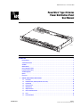
PowerWorx® Type 70 Series
Power Distribution Panel
User Manual
17068-A
Content
Page
INTRODUCTION . . . . . . . . . . . . . . . . . . . . . . . . . . . . . . . . . . . . . . . . . . . . . . . . . . . . . . . . . . . . . . . . . . . . . . . . . . . . . 3
Revision History. . . . . . . . . . . . . . . . . . . . . . . . . . . . . . . . . . . . . . . . . . . . . . . . . . . . . . . . . . . . . . . . . . . . . . . . 3
Trademark Information . . . . . . . . . . . . . . . . . . . . . . . . . . . . . . . . . . . . . . . . . . . . . . . . . . . . . . . . . . . . . . . . . . . 3
Standards . . . . . . . . . . . . . . . . . . . . . . . . . . . . . . . . . . . . . . . . . . . . . . . . . . . . . . . . . . . . . . . . . . . . . . . . . . . . 3
Admonishments . . . . . . . . . . . . . . . . . . . . . . . . . . . . . . . . . . . . . . . . . . . . . . . . . . . . . . . . . . . . . . . . . . . . . . . . 3
General Safety Precautions . . . . . . . . . . . . . . . . . . . . . . . . . . . . . . . . . . . . . . . . . . . . . . . . . . . . . . . . . . . . . . . . 4
Important Product Features . . . . . . . . . . . . . . . . . . . . . . . . . . . . . . . . . . . . . . . . . . . . . . . . . . . . . . . . . . . . . . . . 4
Standard Equipment . . . . . . . . . . . . . . . . . . . . . . . . . . . . . . . . . . . . . . . . . . . . . . . . . . . . . . . . . . . . . . . . . . . . . 5
Options . . . . . . . . . . . . . . . . . . . . . . . . . . . . . . . . . . . . . . . . . . . . . . . . . . . . . . . . . . . . . . . . . . . . . . . . . . . . . . 5
Accessories . . . . . . . . . . . . . . . . . . . . . . . . . . . . . . . . . . . . . . . . . . . . . . . . . . . . . . . . . . . . . . . . . . . . . . . . . . . 5
1
1088905 Rev A
GENERAL CHARACTERISTICS AND FEATURES . . . . . . . . . . . . . . . . . . . . . . . . . . . . . . . . . . . . . . . . . . . . . . . . . . . 8
1.1
Power Buses . . . . . . . . . . . . . . . . . . . . . . . . . . . . . . . . . . . . . . . . . . . . . . . . . . . . . . . . . . . . . . . . . . . .10
1.2
Redundant Power (Uninterrupted Power Fuse Panel) . . . . . . . . . . . . . . . . . . . . . . . . . . . . . . . . . . . . . . . . .10
1.3
Input Voltage . . . . . . . . . . . . . . . . . . . . . . . . . . . . . . . . . . . . . . . . . . . . . . . . . . . . . . . . . . . . . . . . . . . .10
1.4
Input Connectors. . . . . . . . . . . . . . . . . . . . . . . . . . . . . . . . . . . . . . . . . . . . . . . . . . . . . . . . . . . . . . . . . .11
1.5
Output Voltage . . . . . . . . . . . . . . . . . . . . . . . . . . . . . . . . . . . . . . . . . . . . . . . . . . . . . . . . . . . . . . . . . . .12
1.6
Output Connectors . . . . . . . . . . . . . . . . . . . . . . . . . . . . . . . . . . . . . . . . . . . . . . . . . . . . . . . . . . . . . . . .12
1.7
Chassis Ground Connection . . . . . . . . . . . . . . . . . . . . . . . . . . . . . . . . . . . . . . . . . . . . . . . . . . . . . . . . . .12
1.8
Fuses . . . . . . . . . . . . . . . . . . . . . . . . . . . . . . . . . . . . . . . . . . . . . . . . . . . . . . . . . . . . . . . . . . . . . . . . .12
1.9
Power-On Indicator . . . . . . . . . . . . . . . . . . . . . . . . . . . . . . . . . . . . . . . . . . . . . . . . . . . . . . . . . . . . . . . .13
Page 1
© 2001, ADC Telecommunications, Inc.
ADCP-80-524 • Issue 1 • November 2001
1.10 Fuse Alarm Indicator . . . . . . . . . . . . . . . . . . . . . . . . . . . . . . . . . . . . . . . . . . . . . . . . . . . . . . . . . . . . . . 13
1.11 Alarm Contact Operation . . . . . . . . . . . . . . . . . . . . . . . . . . . . . . . . . . . . . . . . . . . . . . . . . . . . . . . . . . . 13
1.12 Alarm Contact Connection . . . . . . . . . . . . . . . . . . . . . . . . . . . . . . . . . . . . . . . . . . . . . . . . . . . . . . . . . . 13
1.13 Fuse Designation Strips and Perforated Cards. . . . . . . . . . . . . . . . . . . . . . . . . . . . . . . . . . . . . . . . . . . . . 13
1.14 Fused Equipment Designation Card and Holder . . . . . . . . . . . . . . . . . . . . . . . . . . . . . . . . . . . . . . . . . . . . 14
1.15 Voltage Designation Label . . . . . . . . . . . . . . . . . . . . . . . . . . . . . . . . . . . . . . . . . . . . . . . . . . . . . . . . . . 14
1.16 Material and Finish . . . . . . . . . . . . . . . . . . . . . . . . . . . . . . . . . . . . . . . . . . . . . . . . . . . . . . . . . . . . . . . 14
1.17 Cooling . . . . . . . . . . . . . . . . . . . . . . . . . . . . . . . . . . . . . . . . . . . . . . . . . . . . . . . . . . . . . . . . . . . . . . . 15
1.18 Protective Cover . . . . . . . . . . . . . . . . . . . . . . . . . . . . . . . . . . . . . . . . . . . . . . . . . . . . . . . . . . . . . . . . . 15
1.19 Dimensions . . . . . . . . . . . . . . . . . . . . . . . . . . . . . . . . . . . . . . . . . . . . . . . . . . . . . . . . . . . . . . . . . . . . 15
1.20 Weight . . . . . . . . . . . . . . . . . . . . . . . . . . . . . . . . . . . . . . . . . . . . . . . . . . . . . . . . . . . . . . . . . . . . . . . 16
1.21 Color . . . . . . . . . . . . . . . . . . . . . . . . . . . . . . . . . . . . . . . . . . . . . . . . . . . . . . . . . . . . . . . . . . . . . . . . . 16
1.22 Mounting . . . . . . . . . . . . . . . . . . . . . . . . . . . . . . . . . . . . . . . . . . . . . . . . . . . . . . . . . . . . . . . . . . . . . . 16
1.23 Environmental Characteristics . . . . . . . . . . . . . . . . . . . . . . . . . . . . . . . . . . . . . . . . . . . . . . . . . . . . . . . 17
2
ACCESSORIES . . . . . . . . . . . . . . . . . . . . . . . . . . . . . . . . . . . . . . . . . . . . . . . . . . . . . . . . . . . . . . . . . . . . . . . . 17
3
UNPACKING AND INSPECTION . . . . . . . . . . . . . . . . . . . . . . . . . . . . . . . . . . . . . . . . . . . . . . . . . . . . . . . . . . . . . 18
4
INSTALLATION . . . . . . . . . . . . . . . . . . . . . . . . . . . . . . . . . . . . . . . . . . . . . . . . . . . . . . . . . . . . . . . . . . . . . . . . 18
4.1
Recommended Installation Tools . . . . . . . . . . . . . . . . . . . . . . . . . . . . . . . . . . . . . . . . . . . . . . . . . . . . . 18
4.2
Use of Screws in Installation Package . . . . . . . . . . . . . . . . . . . . . . . . . . . . . . . . . . . . . . . . . . . . . . . . . . 20
4.3
Protective Cover . . . . . . . . . . . . . . . . . . . . . . . . . . . . . . . . . . . . . . . . . . . . . . . . . . . . . . . . . . . . . . . . . 21
4.4
Cable Management Bar (Accessory for Fuse Panels) . . . . . . . . . . . . . . . . . . . . . . . . . . . . . . . . . . . . . . . . 21
4.5
Rack Mounting . . . . . . . . . . . . . . . . . . . . . . . . . . . . . . . . . . . . . . . . . . . . . . . . . . . . . . . . . . . . . . . . . . 22
4.6
General Wiring Recommendations . . . . . . . . . . . . . . . . . . . . . . . . . . . . . . . . . . . . . . . . . . . . . . . . . . . . 24
4.7
Chassis Ground Connection . . . . . . . . . . . . . . . . . . . . . . . . . . . . . . . . . . . . . . . . . . . . . . . . . . . . . . . . . 25
4.8
Output Power Connectors . . . . . . . . . . . . . . . . . . . . . . . . . . . . . . . . . . . . . . . . . . . . . . . . . . . . . . . . . . . 26
4.9
External Alarm Contact Connectors . . . . . . . . . . . . . . . . . . . . . . . . . . . . . . . . . . . . . . . . . . . . . . . . . . . . 26
4.10 Input Power Connectors . . . . . . . . . . . . . . . . . . . . . . . . . . . . . . . . . . . . . . . . . . . . . . . . . . . . . . . . . . . . 27
4.11 Designation Strips and Perforated Cards . . . . . . . . . . . . . . . . . . . . . . . . . . . . . . . . . . . . . . . . . . . . . . . . 28
4.12 Fuse Designation Card Holder and Card . . . . . . . . . . . . . . . . . . . . . . . . . . . . . . . . . . . . . . . . . . . . . . . . . 28
4.13 Voltage Designation Label . . . . . . . . . . . . . . . . . . . . . . . . . . . . . . . . . . . . . . . . . . . . . . . . . . . . . . . . . . 29
5
TESTING . . . . . . . . . . . . . . . . . . . . . . . . . . . . . . . . . . . . . . . . . . . . . . . . . . . . . . . . . . . . . . . . . . . . . . . . . . . . 29
5.1
Quality Control . . . . . . . . . . . . . . . . . . . . . . . . . . . . . . . . . . . . . . . . . . . . . . . . . . . . . . . . . . . . . . . . . . 29
5.2
Resistance Test . . . . . . . . . . . . . . . . . . . . . . . . . . . . . . . . . . . . . . . . . . . . . . . . . . . . . . . . . . . . . . . . . 29
5.3
Wiring Connections Torque Measurements . . . . . . . . . . . . . . . . . . . . . . . . . . . . . . . . . . . . . . . . . . . . . . . 29
5.4
Power Indication Test . . . . . . . . . . . . . . . . . . . . . . . . . . . . . . . . . . . . . . . . . . . . . . . . . . . . . . . . . . . . . 29
5.5
Connection Polarity Test . . . . . . . . . . . . . . . . . . . . . . . . . . . . . . . . . . . . . . . . . . . . . . . . . . . . . . . . . . . 30
5.6
Fuse Alarm Test . . . . . . . . . . . . . . . . . . . . . . . . . . . . . . . . . . . . . . . . . . . . . . . . . . . . . . . . . . . . . . . . . 30
6
OPERATION . . . . . . . . . . . . . . . . . . . . . . . . . . . . . . . . . . . . . . . . . . . . . . . . . . . . . . . . . . . . . . . . . . . . . . . . . . 30
7
MAINTENANCE . . . . . . . . . . . . . . . . . . . . . . . . . . . . . . . . . . . . . . . . . . . . . . . . . . . . . . . . . . . . . . . . . . . . . . . . 30
8
7.1
Inspection . . . . . . . . . . . . . . . . . . . . . . . . . . . . . . . . . . . . . . . . . . . . . . . . . . . . . . . . . . . . . . . . . . . . . 30
7.2
Cleaning . . . . . . . . . . . . . . . . . . . . . . . . . . . . . . . . . . . . . . . . . . . . . . . . . . . . . . . . . . . . . . . . . . . . . . 31
7.3
Adjustments . . . . . . . . . . . . . . . . . . . . . . . . . . . . . . . . . . . . . . . . . . . . . . . . . . . . . . . . . . . . . . . . . . . . 31
7.4
LED Replacement . . . . . . . . . . . . . . . . . . . . . . . . . . . . . . . . . . . . . . . . . . . . . . . . . . . . . . . . . . . . . . . . 31
CUSTOMER INFORMATION AND ASSISTANCE. . . . . . . . . . . . . . . . . . . . . . . . . . . . . . . . . . . . . . . . . . . . . . . . . . . 32
_________________________________________________________________________________________________________
Page 2
© 2001, ADC Telecommunications, Inc.
ADCP-80-524 • Issue 1 • November 2001
INTRODUCTION
®
This manual describes the PowerWorx Type 70 Series Power Distribution Panels and provides
installation, test, operation, and maintenance procedures. Two types of PowerWorx Type 70
power distribution fuse panels are available: the traditional power distribution fuse panel and
the uninterrupted power distribution fuse panel. Within this manual, the fuse panels are
referred to as the “traditional fuse panel” and “uninterrupted fuse panel.”
Revision History
ISSUE
DATE
Issue 1
11/2001
REASON FOR CHANGE
Original
Trademark Information
ADC and PowerWorx are registered trademarks of ADC Telecommunications, Inc.
Standards
Type 70 series fuse panels are compliant with all major standards including UL, NEC 1999, and
CSA standards. The fuse panel design places great emphasis on high reliability and simplicity
of operation.
Admonishments
Important safety admonishments are used throughout this manual to warn of possible hazards to
persons or equipment. An admonishment identifies a possible hazard and then explains what
may happen if the hazard is not avoided. The admonishments — in the form of Dangers,
Warnings, and Cautions — must be followed at all times. These warnings are flagged by use of
the triangular alert icon (seen below), and are listed in descending order of severity of injury or
damage and likelihood of occurrence.
Danger: Danger is used to indicate the presence of a hazard that will cause severe personal
injury, death, or substantial property damage if the hazard is not avoided.
Warning: Warning is used to indicate the presence of a hazard that can cause severe personal
injury, death, or substantial property damage if the hazard is not avoided.
Caution: Caution is used to indicate the presence of a hazard that will or can cause minor
personal injury or property damage if the hazard is not avoided.
Page 3
© 2001, ADC Telecommunications, Inc.
ADCP-80-524 • Issue 1 • November 2001
General Safety Precautions
-
Caution: The fuse panel uses electrical voltage and amperage levels which, per GR-1089, may
be considered an electrical hazard. Care should be exercised to assure that only qualified
personnel are allowed to install, operate, maintain, or otherwise come in contact with this
equipment when the panel is energized. Only insulated tools should be used on energized
elements of the panel.
Caution: All fuse panel wiring and cabling should be connected with the system office battery
input off or disconnected at the office distribution panel.
Caution: A replacement fuse must be the same type and must have exactly the same current
rating as the fuse being replaced.
Important Product Features
Both the traditional and uninterrupted fuse panel provide dc power over two separate buses
(feeds). However, with the uninterrupted fuse panel, when one bus loses input power, the other
bus supplies the output power for both buses.
Application: Type 70 series fuse panels are used to supply protected dc power to the various
types of telecommunications products typically used in central offices, multimedia headends,
remote sites, and other locations.
Input Power: Type 70 series fuse panels contain two buses (feeds) that accept –24 Vdc or –48
Vdc input power. The traditional fuse panel is rated at 65 Amps input current per bus for a total
output current of 130 Amps per fuse panel. The uninterrupted fuse panel is rated at 60 Amps
input current per bus but the total output current cannot exceed 60 Amps per panel. During
back-up operation, the uninterrupted can supply an output current of up to 30 Amps per bus or
one half of the 60 Amps input current provided by the working power source.
Output Power: Type 70 series fuse panels provide fuse protected output power with up to 8
fuse positions per bus. The selectable current rating for each fuse can be standard amperage
capacity type 70 fuses up to 10 Amps.
Type 70 series fuse panels incorporate several important features:
• Self-configuring input voltage (–24 Vdc or –48 Vdc) capability with up to 65 Amps per
bus (traditional fuse panel) and 60 Amps per bus (uninterrupted fuse panel) to simplify
installation and allow their use in most dc voltage applications
• A colored indicator that projects from the center of a blown type 70 fuse to quickly and
easily identify the affected fuse position
• Alarm contact connections built into the fuse panel for connection to external visual,
audio, and remote alarms
• Field-replaceable high-brilliance Power-On green and Alarm red LED indicators
• Easily-removable smoked plastic protective cover over connectors to enhance safety and
panel accessibility
• Two-post grounding to ensure robust and reliable ground connectivity
Page 4
© 2001, ADC Telecommunications, Inc.
ADCP-80-524 • Issue 1 • November 2001
Standard Equipment
Type 70 series fuse panels have two power buses (feeds). The capacity of each bus is eight fuse
positions with up to 10 Amps per fuse position (within the maximum bus capacity). Each bus
has Power-On and Alarm indicators on the front of the chassis and input, output, ground, and
alarm contact connections on the rear of the chassis.
The current capacity of each bus of the traditional power fuse panel is 65 Amps maximum (130
Amps per panel). The current capacity of each bus of the uninterrupted power fuse panel is 60
Amps maximum (60 Amps per panel).
The power dissipation of each fuse panel is 40 watts maximum at 130 Amps.
The dimensions of each fuse panel are 1.75 inches (4.45 centimeters) high, 17.13 inches (43.51
centimeters) wide, and 10.01 inches (25.42 centimeters) deep (does not include depth of
protective cover and connectors, fuses, and visual indicators that extend beyond the chassis.
Two sets of mounting brackets are provided with each fuse panel, one set for 19-inch (48.3 cm)
rack installations and one set for 23-inch (58.4 cm) rack installations. The fuse panel can be
flush or recess mounted in equipment racks with WECO or EIA hole spacing.
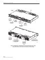
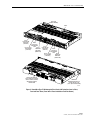
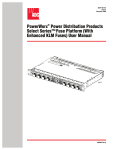
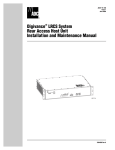
A typical traditional power fuse panel with protective cover in place is shown in Figure 1. A typical
uninterrupted power fuse panel with protective cover in place is shown in Figure 2.
Fuse panels are shipped without fuses. The required fuses are available separately as accessory
items.
Options
All fuse panels are available with the following options:
• Two types of output connectors: screw-down terminal strip connectors or set screw barrel
terminal strip connectors
• Two types of input connectors are available: two-hole compression-lug (stud-type) or set
screw barrel connectors
• The fuse panel color is either putty white or black color
Accessories
The following accessories are available:
• Standard type 70 fuses with standard values from 0.2 Amp to 10.0 Amps
• Cable management bar kit
• Four sizes of compression connector lugs for input power connections
• Fused equipment designation card kit
• Fuse designation card kit
Page 5
© 2001, ADC Telecommunications, Inc.
ADCP-80-524 • Issue 1 • November 2001
UL/CSA/CE
LABEL
BUS A
FUSE FAILURE
INDICATOR
(RED LED)
BUS A TYPE 70
FUSE HOLDER
(8 PER BUS)
VENTS
BUS A
POWER-ON
INDICATOR
(GREEN LED)
BUS B
FUSE FAILURE
INDICATOR
(RED LED)
BUS B TYPE 70
FUSE HOLDER
(8 PER BUS)
BUS B INPUT
CONNECTORS
(SET SCREW
BARREL TYPE
SHOWN)
PROTECTIVE COVER
IN PLACE OVER
OUTPUT POWER, GROUND,
AND ALARM CONTACT
CONNECTIONS
BUS B
POWER-ON
INDICATOR
(GREEN LED)
UNIVERSAL
MOUNTING BRACKETS (2)
(INSTALLED FOR 19-IN.
(48.76 CM) RACK MOUNTING)
BUS A INPUT
CONNECTORS
(SET SCREW
BARREL TYPE
SHOWN)
Figure 1. PowerWorx Type 70 Traditional Fuse Panel with Protective Cover in Place,
Front and Rear Views (Panel with 8 Fuses Installed on Each Bus Shown)
Page 6
© 2001, ADC Telecommunications, Inc.
17067-A
ADCP-80-524 • Issue 1 • November 2001
HEAT SINK
(PATENT PENDING)
VENTS
BUS A
FUSE FAILURE
INDICATOR
(RED LED)
BUS A
FUSE VALUE
DESIGNATION
BUS B
STRIP
FUSE FAILURE
BUS A TYPE 70
BUS A
INDICATOR
FUSE HOLDER
POWER-ON
(RED LED)
(8 PER BUS)
INDICATOR
(GREEN LED)
BUS B
FUSE VALUE
DESIGNATION
STRIP
BUS B TYPE 70
BUS B
FUSE HOLDER
POWER-ON
(8 PER BUS)
INDICATOR
(GREEN LED)
PROTECTIVE COVER IN
PLACE OVER INPUT POWER,
OUTPUT POWER, GROUND,
AND ALARM CONTACT
CONNECTIONS
UNIVERSAL
MOUNTING BRACKETS (2)
(INSTALLED FOR 19-IN.
(48.76 CM) RACK MOUNTING)
16149-B
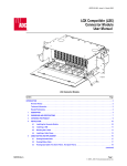
Figure 2. PowerWorx Type 70 Uninterrupted Fuse Panel with Protective Cover in Place,
Front and Rear Views (Panel with 8 Fuses Installed on Each Bus Shown)
Page 7
© 2001, ADC Telecommunications, Inc.
ADCP-80-524 • Issue 1 • November 2001
1
GENERAL CHARACTERISTICS AND FEATURES
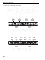
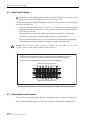
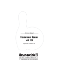
This section describes the general characteristics and features of the traditional and
uninterrupted fuse panels. The front of a typical traditional power fuse panel is shown in
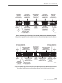
Figure 3. The front of a typical uninterrupted power fuse panel is shown in Figure 4. The rear
side of the traditional power fuse panel (with protective cover removed to view the optional
connections) is shown in Figure 5. The rear side of the uninterrupted power fuse panel (with the
protective cover removed to view the optional connections) is shown in Figure 6. Options and
features other than those described may be available by special order.
BUS A
FUSE FAILURE
INDICATOR
(RED LED)
BUS A
POWER-ON
INDICATOR
(GREEN LED)
BUS B
FUSE FAILURE
INDICATOR
(RED LED)
BUS B
POWER-ON
INDICATOR
(GREEN LED)
16151-B
BUS A TYPE 70
FUSE HOLDER
(8 PER BUS)
BUS B TYPE 70
FUSE HOLDER
(8 PER BUS)
Figure 3. ADC PowerWorx Type 70 Traditional Fuse Panel, Front View
(Panel with 8 Fuses Installed on Each Bus Shown)
BUS A
FUSE FAILURE
INDICATOR
(RED LED)
BUS A
FUSE VALUE
DESIGNATION
STRIP
BUS A
POWER-ON
INDICATOR
(GREEN LED)
BUS B
FUSE FAILURE
INDICATOR
(RED LED)
BUS B
FUSE VALUE
DESIGNATION
STRIP
BUS B
POWER-ON
INDICATOR
(GREEN LED)
16152-B
BUS A TYPE 70
FUSE HOLDER
(8 PER BUS)
BUS B TYPE 70
FUSE HOLDER
(8 PER BUS)
Figure 4. PowerWorx Type 70 Uninterrupted Fuse Panel, Front View
(Panel with 8 Fuses Installed on Each Bus Shown)
Page 8
© 2001, ADC Telecommunications, Inc.
ADCP-80-524 • Issue 1 • November 2001
BUS B INPUT
CONNECTORS
(TWO HOLE
COMPRESSION
LUG-STUD TYPE) (2)
TO
BATTERY
B
TO
RETURN
B
BATTERY B
OUTPUT POWER
CONNECTORS (SET
SCREW BARREL
TERMINAL TYPE)
BUS A AND BUS B
ALARM CONTACT
CONNECTOR
(WIRE-WRAP PIN
BLOCK TYPE)
BATTERY A
OUTPUT POWER
CONNECTORS (SET
SCREW BARREL
TERMINAL TYPE)
BUS A INPUT
CONNECTORS
(TWO HOLE
COMPRESSION
LUG-STUD TYPE) (2)
BATTERY B
OUTPUT RETURN
CONNECTORS (SET
SCREW BARREL
TERMINAL TYPE)
CHASSIS
GROUND
TERMINALS
BATTERY A
OUTPUT RETURN
CONNECTORS (SET
SCREW BARREL
TERMINAL TYPE)
TO
BATTERY
A
PROTECTIVE COVER
MOUNTING STANDOFFS
(2 SETS OF 4)
TO
RETURN
A
16155-A
Figure 5. PowerWorx Type 70 Fuse Panel, Rear View with Protective Cover Removed (Panel with
Compression Lug Input Connectors and Set Screw Barrel Terminal Strip Output Connectors Shown)
BUS A INPUT CONNECTORS
(SET SCREW BARREL TYPE)
BUS B INPUT CONNECTORS
(SET SCREW BARREL TYPE)
TO
BATTERY
B
TO
RETURN
B
INTERNAL
CONNECTIONS.
DO NOT REMOVE
CAPS OR
TURN SCREWS
BUS B OUTPUT POWER
CONNECTORS (SCREWDOWN BARRIER
TERMINAL STRIP TYPE)
BUS B OUTPUT RETURN
CONNECTORS (SCREWDOWN BARRIER
TERMINAL STRIP TYPE)
PROTECTIVE COVER
MOUNTING STANDOFFS
(2 SETS OF 2)
BUS A AND BUS B
ALARM CONTACT
CONNECTOR
(WIRE-WRAP PIN
BLOCK TYPE)
CHASSIS
GROUND
TERMINALS
BUS A OUTPUT POWER
CONNECTORS (SCREWDOWN BARRIER
TERMINAL STRIP TYPE)
BUS A OUTPUT RETURN
CONNECTORS (SCREWDOWN BARRIER
TERMINAL STRIP TYPE)
TO
BATTERY
A
INTERNAL
TO
CONNECTIONS. RETURN
DO NOT REMOVE
A
CAPS OR
TURN SCREWS
16154-B
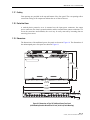
Figure 6. PowerWorx Type 70 Fuse Panel, Rear View with Protective Cover Removed (Panel with Set
Screw Barrel Input Connectors and Screw-Down Barrier Terminal Strip Connectors Shown)
Page 9
© 2001, ADC Telecommunications, Inc.
ADCP-80-524 • Issue 1 • November 2001
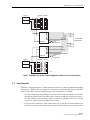
1.1
Power Buses
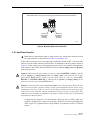
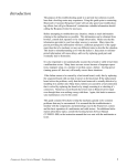
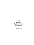
Each fuse panel has two separate power buses (feeds). Each bus distributes the input power to
the output power circuits. In each bus circuit, current flows from the input power bus, through
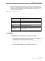
the fuse, to the output power circuit. A typical fuse panel block diagram is shown in Figure 7.
The current capacity of each bus of the traditional power fuse panel is 65 Amps maximum. The
output fusing of the traditional fuse panel should not exceed 65 Amps per bus. This provides a
total capacity of 130 Amps per panel. The maximum current per bus is marked on the fuse
panel.
The current capacity of each bus of the uninterrupted power fuse panel is 60 Amps maximum.
However, the output fusing of the uninterrupted fuse panel should not exceed 30 Amps per bus.
This provides a total capacity of 60 Amps per panel. The maximum current per bus is marked
on the fuse panel.
Each of the feed buses has a capacity of eight fuse positions. Other fuse capacity configurations
may be available by special order. When a fuse fails, the input power bus is disconnected from
the corresponding output circuit. This causes the alarm LED for the bus to light and also opens
or closes the alarm relay contacts (form C contacts).
1.2
Redundant Power (Uninterrupted Power Fuse Panel)
The uninterrupted power fuse panel provides redundant power to fused equipment through the
use of Schottky steering diodes. When power to one bus is interrupted, the Schottky steering
diodes enable the other bus to supply power to the entire fuse panel and to maintain output
power for both buses (bus A and bus B). If bus A loses power, bus B will support the power load
of bus A while maintaining its original power load. Likewise, if bus B loses power, bus A will
support the power load of bus B while maintaining its original power load.
1.3
Input Voltage
The fuse panel can accommodate either –24 Vdc on both buses or –48 Vdc on both buses. The
voltage level is sensed by the fuse panel circuitry. The input voltage used with the fuse panel can
have the following characteristics:
• –24 Vdc nominal, within range of –21 Vdc to –30 Vdc
• –48 Vdc nominal, within range of –42 Vdc to –56 Vdc
Fuse panels for use with other input voltage and polarity power may be available by special
order.
Page 10
© 2001, ADC Telecommunications, Inc.
ADCP-80-524 • Issue 1 • November 2001
–24V/–48V
BATTERY
BATTERY A
RETURN
1
2
3
4
5
6
7
8
RETURN A
BUS A
C
NO
NC
POWER A LED
FUSE
ALARM A LED
RETURN A
POWER B LED
FUSE
ALARM B LED
RETURN B
BATTERY B
RETURN B
BATTERY
C
NO
NC
BUS B
–24V/–48V
SYSTEM ALARM
CONNECTIONS
RETURN
1
2
3
4
5
6
7
8
16758-A
Figure 7. PowerWorx Type 70 Fuse Panel Block Diagram (Traditional Power Fuse Panel Shown)
1.4
Input Connectors
Each bus is equipped with two (2) input connectors on the rear of the fuse panel through which
input power is applied. The two input power connectors are labeled BATT (battery) and RTN
(return) on the fuse panel. The following types of input connectors are available:
• Two-hole compression lug (stud type) connectors: Each connector consists of two studs
mounted on a plated copper bar and two nuts. Each set of studs can accept various size 2hole lugs which can be used with a number of wire sizes ranging from #14 to #2 AWG
copper wire. Various lugs are available as accessories.
• Set screw barrel connectors: Each connector has two (2) barrels. On each connector, the
barrel that is closest to the outside of the fuse panel (barrel without a cap) is used to secure
Page 11
© 2001, ADC Telecommunications, Inc.
ADCP-80-524 • Issue 1 • November 2001
the wire to the connector. The barrel on each connector that is closest to the center of the
fuse panel (barrel with a cap over it) is not used or accessed. The wire is inserted into the
connector and the set screw is tightened down, compressing the wire. The set screw barrel
connectors can accept up to #6 AWG copper wire.
1.5
Output Voltage
The output voltage will be the same voltage as the applied input voltage when the fuse does not fail.
1.6
Output Connectors
Each output circuit has two connectors through which the output power is accessed for
connection to telecommunications equipment. The following types of output connectors are
available:
• Screw-down barrier terminal strip: Eight terminals with 6-32 screws are mounted in two
barrier type terminal strips per bus (one strip for input and one strip for return). The
terminals are on 0.375 inch (9.525 mm) centers with a maximum distance between
barriers (maximum connecting terminal width) of 0.325 inch (8.255 mm). Terminals can
accept #12 to #22 AWG copper wire with crimp-on spade lug or ring connectors or wires
with the insulation stripped back.
• Set screw barrel terminal strip: Eight barrel terminals are mounted in two set screw barrel
terminal strips per bus (one strip for input and one strip for return). The terminals are on
0.197 inch (5.004 mm) centers. Terminals can accept #12 to #26 AWG copper wire with
insulation stripped back.
1.7
Chassis Ground Connection
Two #10 studs mounted on 0.625 inch (15.875 mm) centers are provided for grounding the fuse
panel chassis. This chassis ground connection can be used to attach a separate grounding
conductor when mounting the fuse panel in non-grounded or non-conducting material or when
required by local practice. The studs can accommodate 2-hole lugs and up to #6 AWG wire.
Two crimp ring lug terminals for use with #10 AWG wire are enclosed with the fuse panel. The
fuse panel can be properly grounded using only one grounding stud.
1.8
Fuses
The fuse panel accommodates industry standard type 70 fuses with values from 0.02 Amp to
10.0 Amps in any fuse position within the maximum capacity of the bus (total fuse load cannot
exceed bus capacity). The maximum fuse value that can be used in each fuse position is 10.0
Amps which is marked on the front panel.
The type 70 fuse contains a colored indicator that designates the fuse value. When the fuse
blows, the indicator extends out of the fuse to indicate that the fuse has blown. Fuse panels are
shipped without fuses installed. Standard type 70 fuses are available from ADC.
Page 12
© 2001, ADC Telecommunications, Inc.
ADCP-80-524 • Issue 1 • November 2001
1.9
Power-On Indicator
A visual power-on indicator (green LED) for each power bus is mounted on the front panel of
the fuse panel. A lighted LED indicates that power is applied to the bus input connectors. An
unlighted LED indicates that power is not applied to the bus input connectors. The LED can
easily be replaced in the field if it fails.
1.10 Fuse Alarm Indicator
A visual fuse alarm indicator (red LED) is provided on the front panel for each power bus. The
fuse alarm indicator lights when any fuse on the corresponding bus fails. The fuse alarm
indicator is off when all fuses on the corresponding bus are operational. Loss of power to a bus
will not cause the fuse alarm indicator corresponding to that bus to be lighted. The LED can be
easily replaced in the field if it fails.
1.11 Alarm Contact Operation
Each bus contains circuitry that opens and closes a set of alarm contacts when any fuse on the
bus fails or when the input power to the bus is lost. These contacts may be used to open or close
a loop connected to an external alarm system.
The alarm circuitry provides Form C alarm relay contacts. During normal operation, the
normally open (NO) contacts remain open and the normally closed (NC) contacts remain
closed. When a fuse fails on either bus or power to either bus is lost, the NO contacts close
creating a connection between NO and common (C) and the NC contacts open creating an open
circuit between NC and common. The current rating for each set of alarm relay contacts (three
sets are provided) is 1.0 Amp maximum.
1.12 Alarm Contact Connection
Alarm contact connections are provided through three sets of wire wrap pins located on the rear
side of the fuse panel. Each set of wire wrap pins is labeled with a suggested use for monitoring
the fuse panel: audio, visual, and remote. The wire wrap pins can accept #22 to #26 AWG
copper wire.
1.13 Fuse Designation Strips and Perforated Cards
Plastic designation strips with clear plastic covers are mounted above the fuse holders for each
bus. Four card sheets, each with three perforated strips, are provided with the fuse panel. The
perforated strips may be marked with the circuit designations/fuse values for each circuit/fuse
on the bus. The perforated strips are then inserted into the designation strips so that the
information on the perforated strip is positioned above the corresponding fuses. Additional
perforated strip cards and plastic covers can be ordered from ADC if required.
Page 13
© 2001, ADC Telecommunications, Inc.
ADCP-80-524 • Issue 1 • November 2001
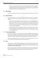
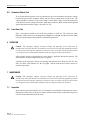
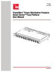
1.14 Fused Equipment Designation Card and Holder
Two fuse designation cards, shown in Figure 8, and a card holder with a clear plastic cover are
provided with the fuse panel. The card holder may be attached to the fuse panel, the fuse panel
mounting brackets, to the rack, or a location close to the fuse panel. One of the cards may be
filled out with circuit information for each of the circuits and inserted in the card holder. The
card holder has a pressure sensitive adhesive backing for attachment. Additional fused
equipment designation cards, card holders, and plastic covers can be ordered from ADC if
required.
1.60 IN.
(4.06 CM)
1.60 IN.
(4.06 CM)
2.36 IN.
(5.99 CM)
2.36 IN.
(5.99 CM)
20 POSITION CARD
10 POSITION A AND B CARD
12486-C
Figure 8. Fuse Designation Cards
1.15 Voltage Designation Label
A voltage designation label, shown in Figure 9, is provided with the fuse panel. The label may
be filled out with the actual voltage present on the buses and placed on the panel. The voltage
designation label has a pressure sensitive adhesive backing for attachment.
0.38 IN.
(0.96 CM)
14228-A
1.00 IN.
(2.54 CM)
Figure 9. Voltage Designation Label
1.16 Material and Finish
The fuse panel chassis and brackets are made of 16-gauge cold rolled steel. The panel and
brackets are finished with powder paint.
Page 14
© 2001, ADC Telecommunications, Inc.
ADCP-80-524 • Issue 1 • November 2001
1.17 Cooling
Vent openings are provided in the top and bottom of the fuse panel. The vent openings allow
convection cooling of all components without the use of fans or blowers.
1.18 Protective Cover
A smoked plastic protective cover is mounted over the input power connectors, the output
power connectors, the chassis ground terminals, and the external alarm contact connections. To
access the connectors and terminals, the cover may be easily removed by loosening (but not
removing) four screws.
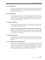
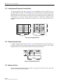
1.19 Dimensions
The dimensions of the traditional power fuse panel are shown in Figure 10. The dimensions of
the uninterrupted power fuse panel are shown in Figure 11.
10.01 IN.
(25.42 CM)
11.35 IN.
(28.82 CM)
17.13 IN.
(43.51 CM)
19.0 IN.
(48.26 CM)
18.31 IN.
(46.51 CM)
1.13 IN.
1.75 IN.
(2.86 CM) (4.45 CM)
16158-B
Figure 10. Dimensions of Type 70 Traditional Power Fuse Panel
(with Mounting Brackets Attached for 19-Inch [48.26 cm] Rack Mounting)
Page 15
© 2001, ADC Telecommunications, Inc.
ADCP-80-524 • Issue 1 • November 2001
10.01 IN.
(25.42 CM)
11.35 IN.
(28.82 CM)
17.13 IN.
(43.51 CM)
19.0 IN.
(48.26 CM)
18.31 IN.
(46.51 CM)
1.13 IN.
1.73 IN.
(2.86 CM) (4.39 CM)
16157-B
Figure 11. Dimensions of Type 70 Uninterrupted Power Fuse Panel
(with Mounting Brackets Attached for 19-Inch [48.26 cm] Rack Mounting)
1.20 Weight
The weight of both the traditional and uninterrupted fuse panel is approximately 14 pounds
(6.35 kilograms). The actual weights are dependent upon the configurations of the panels.
1.21 Color
The color of the fuse panel and mounting brackets is either putty white or black.
1.22 Mounting
The fuse panel can be mounted in either a 19- or 23-inch (48.26 or 58.42 cm) equipment rack.
Both the traditional and the uninterrupted panel are equipped with two sets (one set for 19-inch
racks and one set for 23-inch racks) of mounting brackets. The panel can be flush mounted or
recessed 1, 2, 3, or 4 inches (25.4, 50.8, 76.2, or 101.6 mm) from the front of the rack. The
Page 16
© 2001, ADC Telecommunications, Inc.
ADCP-80-524 • Issue 1 • November 2001
mounting brackets allow mounting with WECO 1.00-inch (2.54 cm) hole spacing or EIA 1.25inch (3.18 cm) hole spacing. The slotted mounting hole pattern in the mounting brackets
compensates for vertical rack differences and allows mounting the fuse panel in either 1.75- or
2-inch (4.45 or 5.08 cm) rack spaces.
1.23 Environmental Characteristics
The environmental characteristics of the PowerWorx Type 70 Series Power Distribution Fuse
Panel are listed in Table 1.
Table 1. PowerWorx Type 70 Fuse Panel Environmental Characteristics
2
PARAMETER
DESCRIPTION
Operating temperature
–5° C to +50° C
Storage temperature
–45° C to +85° C
Humidity range
0% to 95% humidity (non-condensing)
Altitude range
–197 ft. (0.06 km) to 13,000 ft. (3.96 km) above sea level
Fire rating
All components UL94-V1 or better
Acoustic noise
0 dBA above ambient
Heat dissipation (fully loaded
traditional panel)
40 watts maximum@ 65 A per bus, 80 watts maximum @ 130 A
total fuse panel load
Heat dissipation (no load)
1 watt per bus
ACCESSORIES
The following accessories for the PowerWorx Type 70 fuse panel are available:
• Standard Type 70 fuses with current capacity of from 0.2 Amp to 10.0 Amps
• Cable management bar with mounting screws. Provides cable tie points. Installed at rear
of fuse panel by fastening ends of bar to both sides of the panel
• Four sizes of two-hole compression lugs for #2, #4, #6, and #14 AWG wire for input
power connection
• Kit of perforated fuse value designation cards and plastic covers
• Kit of fused equipment designation cards, a card holder, and a plastic cover
Page 17
© 2001, ADC Telecommunications, Inc.
ADCP-80-524 • Issue 1 • November 2001
3
UNPACKING AND INSPECTION
Unpack and inspect the various components as follows:
1. Inspect the exterior of the shipping container for evidence of handling that may have
damaged the components in the container.
2. Unpack each container while carefully checking the contents for damage and verify with
the packing slip.
3. File a claim with the commercial carrier and notify ADC Customer Service if damage is
detected or if parts are missing. Save damaged cartons for inspection by the carrier.
4. Refer to Section 8, Customer Information and Assistance, at the back of this manual, for
repair, replacement, and warranty information.
5. Save all shipping containers for use if the equipment requires return shipment at a future date.
4
INSTALLATION
Fuse panels must be installed in a central office, equipment room, or restricted access location.
The following guidelines should be used when mounting the fuse panel in a rack.
• Mount the fuse panel in the uppermost area of the rack to reduce exposure of the power
wiring.
• Provide a minimum of 1.75 inches (4.45 cm) of air space (one rack space) between the top
of the fuse panel and the next item in the rack for cooling.
• Adding a fuse panel to a rack may displace a device which may require relocation.
Caution: This equipment employs electrical voltage and amperage levels which may be
considered an electrical hazard. Care should be exercised to assure that only qualified
personnel are allowed to install, operate, maintain, or otherwise come in contact with this
equipment when the fuse panel is energized. Only insulated tools should be used on energized
elements of the fuse panel.
Warning: Never install telephone equipment in a wet location or during a lightning storm.
When installing or modifying telephone lines, disconnect lines at the network interface before
working with uninsulated lines or terminals to prevent electrical shock.
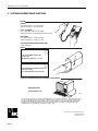
4.1
Recommended Installation Tools
Use common hand tools, such as a Phillips screwdriver, a wire wrap gun and bits, a wire
stripper, and a wire lug crimper to install the fuse panel. In addition to these tools, the following
tools are recommended:
Page 18
© 2001, ADC Telecommunications, Inc.
ADCP-80-524 • Issue 1 • November 2001
• Power screwdriver with Phillips head bit and slotted head bit
PHILLIPS SCREW
HEAD BIT
16776-A
• Set of sockets and driver
16794-A
• Set of open end or box end wrenches
16795-A
Page 19
© 2001, ADC Telecommunications, Inc.
ADCP-80-524 • Issue 1 • November 2001
• Torque screwdriver calibrated in pound-force inches or Newton meters with Phillips head
bit and slotted head bit
16797-A
4.2
Use of Screws in Installation Package
Caution: When installing the fuse panel, use only the hardware supplied with the panel. Use of
any other hardware could cause damage to the panel. If parts are missing, please contact ADC.
Several types of screws are provided with the fuse panel. The screws used with the rackmounting brackets are thread-forming screws which help to provide a solid ground path
between the panel chassis and the rack. Use the power screwdriver to install these screws.
4.2.1
Screws to Attach Brackets to Fuse Panel
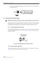
To fasten the mounting brackets to the fuse panel, use the 5/15-inch (7.94 mm) long, black
chromate finish 8-32 flat-head screws as shown in Figure 12. Eight screws (four for each
bracket) are provided.
THREAD FORMING SCREW,
FLAT HEAD UNDERCUT,
PHILLIPS DRIVE
5/16-IN.
(7.936 mm)
8 - 32
THREAD
16977-A
Figure 12. Screw for Attaching Brackets to Power Panel Chassis
4.2.2
Screws to Attach Brackets to Rack
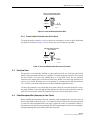
To fasten the mounting brackets to the rack, use the four nickel plated 12-24 screws as shown in
Figure 13. Four screws (two for each bracket) are provided.
Page 20
© 2001, ADC Telecommunications, Inc.
ADCP-80-524 • Issue 1 • November 2001
PAINT CUTTING, TAPPING SCREW,
PAN HEAD, COMBINATION DRIVE
3/8-IN.
(9.53 mm)
12 - 24
THREAD
16592-A
Figure 13. Screw for Attaching Bracket to Rack
4.2.3
Screws to Attach Protective Cover to Fuse Panel
To fasten the plastic protective cover over the power connections, use the tin plate finish 6-32
pan-head screws shown in Figure 14. Four screws (two for each end) are provided.
MACHINE SCREW, PAN HEAD,
PHILLIPS DRIVE
3/8-IN.
(9.53 mm)
6 - 32
THREAD
16593-B
Figure 14. Screw for Attaching Protective Cover to Fuse Panel
4.3
Protective Cover
The protective cover should be installed over the connectors at the rear of the fuse panel when
all the wiring connections and tests are completed. To install the plastic protective cover, thread
the four 3/8-inch (9.53 mm) long, Phillips-drive, 6-32 pan-head screws into the standoffs
located on each output power screw-down barrier strip. Rotate each screw approximately two
turns to get it started. Hold the cover so the lettering is oriented properly and then place the
cover over the screw heads. Slide the cover to the left and then tighten the screws.
To remove the protective cover, loosen but do not remove the four screws that secure the cover to
the panel. Slide the cover to the right and then pull the cover directly outward and away from the
panel. The screws do not need to be completely removed to remove the protective cover.
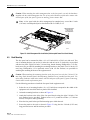
4.4
Cable Management Bar (Accessory for Fuse Panels)
Before installing the fuse panel in the rack, mount the cable management bar (accessory item) on
the rear of the panel as shown in Figure 15. Use the 0.25-inch (6.35 mm) long 4-40 screws provided
to secure the cable management bar to the panel. Tighten all screws to 9 pound force-inches (1
Newton meter) of torque to insure grounding. The cable management bar can be recess mounted by
using the mounting holes closest to the front of the fuse panel.
Page 21
© 2001, ADC Telecommunications, Inc.
ADCP-80-524 • Issue 1 • November 2001
Caution: When attaching the cable management bar to the fuse panel, use only the hardware
supplied with the cable management bar. Use of any other hardware could cause contact with
internal parts of the fuse panel. If parts are missing, please contact ADC.
Note: A fuse panel with the cable management bar attached may exceed the 12-inch
(3.05 mm) overall depth objective described in GR-63 CORE, 02-14.
MOUNTING BRACKET
INSTALLED FOR
19-IN. (48.26 CM)
RACK MOUNTING
ATTACH TO
EITHER SET
OF 3 HOLES
CABLE
MANAGEMENT
BAR
16387-B
Figure 15. Cable Management Bar Installation (Uninterrupted Power Fuse Panel Shown)
4.5
Rack Mounting
The fuse panel can be mounted in either a 19- or 23-inch (48.26 or 58.42 cm) wide rack. Two
sets of mounting brackets, one set for 19-inch racks and one set for 23-inch racks, are provided
with the fuse panel. Eight 5/16-inch (7.94 mm) long, thread-forming, Phillips-drive, 8-32 flathead screws are provided for attaching the mounting brackets to the panel. Four 3/8-inch (9.53
mm) long, Phillips-drive, 12-24 pan-head screws (with #12 flat washers) are provided for
attaching the mounting brackets to the equipment rack.
Caution: When attaching the mounting brackets to the fuse panel, use only the 5/16-inch (7.94
mm) long, black chromate finish, thread forming, flathead screws provided with the panel. Use
of any other hardware could cause contact with internal parts of the panel. If parts are missing,
contact ADC to order replacement parts.
Use the following procedure to install the fuse panel in the equipment rack:
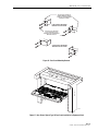
1. Select the set of mounting brackets (19- or 23-inch) that correspond to the width of the
equipment rack into which the fuse panel will be installed.
2. Orient the mounting brackets as shown in Figure 16.
3. Attach the brackets to the sides of the fuse panel chassis using the eight 5/16-inch (7.94
mm) flathead screws provided. Tighten screws to 15 pound force-inches (1.7 Newton
meters) of torque to insure grounding.
4. Place the fuse panel in the specified mounting space within the rack.
5. Secure the panel to the rack as shown in Figure 17 using the four 3/8-inch (9.525 mm)
long pan-head screws and flat washers provided.
Page 22
© 2001, ADC Telecommunications, Inc.
ADCP-80-524 • Issue 1 • November 2001
USE 5/16-INCH (7.94 MM) 8-32
THREAD-FORMING FLAT-HEAD
SCREWS TO SECURE MOUNTING
BRACKETS TO PANEL
19-INCH RACK MOUNTING
BRACKET INSTALLATION
USE 3/8-INCH (9.53 MM) LONG
12-24 SCREWS AND #12 FLAT
WASHERS TO SECURE MOUNTING
BRACKETS TO RACK
23-INCH RACK MOUNTING
BRACKET INSTALLATION
16965-C
Figure 16. Fuse Panel Mounting Brackets
16386-B
Figure 17. Rear View of Typical Type 70 Fuse Panel Installation in Equipment Rack
Page 23
© 2001, ADC Telecommunications, Inc.
ADCP-80-524 • Issue 1 • November 2001
4.6
General Wiring Recommendations
Route and connect ground, power, and alarm cables to the panel connectors according to local
practice and the specified procedures. The connections to the fuse panel are shown in Figure 18.
After routing the cables, tie them to the cable management bar (optional accessory). Replace the
protective cover on the fuse panel after all the wiring connections are made and all tests are
completed.
Caution: Connect both buses of the fuse panel to only –24 Vdc or –48 Vdc.
Caution: Connect only the input voltage wire [the wire labeled BATTERY or BATT, or labeled
with the negative (–) voltage polarity and/or the voltage value] to the connector on the fuse
panel labeled BATT (battery). Connect only the input return wire [the wire labeled RTN,
RETURN, or BATTERY GROUND, or labeled with the positive (+) voltage polarity] to the
connector on the fuse panel labeled RTN (return). If the wires are reversed, voltage could be
present on the fuse panel chassis and current could flow through the unprotected return wiring
in the fuse panel. This condition can cause damage to equipment in the frame in which the fuse
panel is installed and to equipment in adjacent frames!
CONNECT OUTPUT
POWER TERMINALS
TO OUTPUT
POWER CIRCUITS
CONNECT REMOTE
ALARM TERMINALS
TO REMOTE ALARMS
CONNECT OUTPUT
POWER TERMINALS
TO OUTPUT
POWER CIRCUITS
CONNECT TO
BUS B BATTERY*
OUTPUT
POWER
CONNECTORS
OUTPUT
POWER
CONNECTORS
CONNECT TO
BUS B RETURN**
OUTPUT
RETURN
CONNECTORS
OUTPUT
RETURN
CONNECTORS
CONNECT OUTPUT
RETURN TERMINALS
TO OUTPUT
RETURN CIRCUITS
CONNECT TO
EQUIPMENT
RACK
CONNECT INPUT
CONNECTOR TO
BUS A BATTERY*
CONNECT INPUT
CONNECTOR TO
BUS A RETURN**
CONNECT OUTPUT
RETURN TERMINALS
TO OUTPUT
RETURN CIRCUITS
*NOTE: CONNECT INPUT VOLTAGE WIRE LABELED "BATTERY," "BATT," "NEGATIVE," "NEG," OR "-"
AND/OR THE VOLTAGE VALUE TO THE "BATT" CONNECTOR ("HOT" WIRE).
**NOTE: CONNECT INPUT RETURN WIRE LABELED "RTN," "RETURN," "BATTERY GROUND,"
"POSITIVE," "POS," OR "BATTERY GROUND" TO THE "RTN" CONNECTOR.
16159-A
Figure 18. Rear View of Type 70 Fuse Panel Cabling (Panel with Compression Lug Input
Connectors and Screw-Down Barrier Terminal Strip Output Connectors Shown)
Page 24
© 2001, ADC Telecommunications, Inc.
ADCP-80-524 • Issue 1 • November 2001
4.7
Chassis Ground Connection
Mounting the fuse panel on a metal equipment rack using the metal mounting brackets provided
with the fuse panel provides a sufficient return path to meet equipment grounding requirements.
However, a separate grounding conductor is often required by local practice or local inspectors.
A separate chassis grounding conductor is always needed when the fuse panel is mounted to
non-grounded or non-conducting material such as a plastic rack or cabinet. When the panel
requires separate chassis grounding, the chassis grounding conductor must be sized to match the
upstream protection device feeding the panel. This provides an adequate return path capable of
allowing the fuse to fail in the unlikely event of a battery wire to chassis fault.
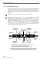
Connect one or both of the chassis ground connectors (labeled C. GND) to the equipment rack
ground (see Figure 19), using the following chassis grounding recommendations:
• Chassis grounding conductor connection point: Two #10 studs (with nuts) on 0.625 inch
(15.875 mm) centers are provided for connecting a grounding conductor to the fuse panel.
• Chassis ground conductor: Use two #10 AWG wires if using both chassis ground
connectors or one #6 AWG wire if using one chassis ground connector. Two #10 crimp
ring terminals (for use with #10 AWG wires) are included with the fuse panel.
• Place the ring terminals over the chassis grounding studs and tighten the stud nuts to
approximately 15 pound-force inches (1.7 Newton meters) of torque.
• Connect the ground conductors to an approved office ground source per local code or
practice.
USE TWO #10 AWG WIRES IF USING BOTH CHASSIS GROUND CONNECTORS OR ONE #6 AWG WIRE IF USING ONLY ONE
CHASSIS GROUND CONNECTOR.
TWO #10 CRIMP RING TERMINALS FOR ATTACHING THE #10 WIRES TO THE CHASSIS CONNECTORS ARE PROVIDED
WITH THE FUSE PANEL.
PLACE THE RING TERMINALS OVER THE CHASSIS SCREWS AND TIGHTEN THE NUTS DOWN ON THE TERMINALS. IF NOT
USING TERMINALS, WRAP THE WIRE(S) AROUND THE CHASSIS SCREW(S) AND TIGHTEN THE NUTS DOWN ON THE WIRES.
CONNECT THE WIRE(S) TO THE EQUIPMENT RACK.
GROUND SCREW AND NUT
GROUND SCREW AND NUT
16160-A
Figure 19. Chassis Ground Connection
Page 25
© 2001, ADC Telecommunications, Inc.
ADCP-80-524 • Issue 1 • November 2001
4.8
Output Power Connectors
Note: Before connecting the output or input power wires, measure the resistance of each
bus input connector as specified in Subsection 5.2, Resistance Test.
Connect the output BATT and RTN terminals for each fuse circuit on each set of terminal strips
as follows (see Figure 20):
• Screw-down barrier terminal strip: Use #12 to #22 AWG wire. Wire leads should be
equipped with crimp-on spade lugs or ring connectors that have a maximum width of
0.325 inches (8.255 mm).
The terminals also accommodate copper wire without lugs (insulation stripped back).
Torque the screws to approximately 9 pound-force inches (1 Newton meter).
• Set screw barrel terminal strip: Use #12 to #24 AWG wire with insulation stripped back.
Tighten the screws to approximately 4.5 pound-force inches (1 Newton meter).
Caution: For screw-down barrier terminal strip outputs, use #12 AWG wire to prevent
personnel contact with the voltages (NEBs standard, Class A2).
CONNECT USING CRIMP-ON SPADE LUGS OR RING CONNECTORS THAT HAVE A MAXIMUM WIDTH OF 0.325 IN.
(8.255 MM) ON #12 TO #22 AWG WIRE OR USING #12 TO #22 AWG WIRE WITH INSULATION STRIPPED BACK.
TORQUE THE SCREWS TO APPROXIMATELY 9 POUND-FORCE INCHES (1 NEWTON METER).
CONNECT TO OUTPUT POWER CIRCUITS
CONNECT TO OUTPUT RETURN CIRCUITS
16766-A
Figure 20. Output Connector Connection (Screw-Down Barrier Terminal Strip Connectors Shown)
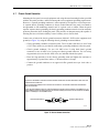
4.9
External Alarm Contact Connectors
Connect each set of external alarm contacts to a local alarm system as required (see Figure 21).
Wrap terminal block pins using #22 to #26 AWG copper wire with insulation stripped back.
Page 26
© 2001, ADC Telecommunications, Inc.
ADCP-80-524 • Issue 1 • November 2001
WRAP TERMINAL BLOCK PINS USING #22 TO #26 AWG COPPER WIRE WITH INSULATION STRIPPED BACK.
CONNECT TO
APPROPRIATE
TERMINALS
OF ALARMS
CONNECT TO
APPROPRIATE
TERMINALS
OF ALARMS
16161-B
Figure 21. Wire Wrap Alarm Contact Connection
4.10 Input Power Connectors
Note: Before connecting the input or output power wires, measure the resistance at each
bus input connector as specified in Subsection 5.2, Resistance Test.
Connect the input power wires to the input power connectors labeled “BATT” and connect the
return wires to the return connectors labeled “RTN” for both buses in the fuse panel as shown in
Figure 22. Connect input power to the appropriate power sources in accordance with applicable
local electrical codes and/or National Electrical Codes but do not apply power to the panel
until directed to do so.
Caution: Connect only the input voltage wire [the wire labeled BATTERY or BATT, or labeled
with the negative (–) voltage polarity and/or the voltage value] to the connector on the fuse
panel labeled BATT (battery). Connect only the input return wire [the wire labeled RTN,
RETURN, or BATTERY GROUND, or labeled with the positive (+) voltage polarity] to the
connector on the fuse panel labeled RTN (return).
Caution: Caution should be taken to not reverse input wires to the fuse panel. Within the fuse
panel, the internal battery (negative voltage) wiring is protected and the internal return wiring
is not protected by fuses. If the wires are reversed, voltage could be present on the fuse panel
chassis and current could flow through the unprotected return wiring in the fuse panel. This
condition can cause damage to equipment in the frame in which the fuse panel is installed and
to equipment in adjacent frames
• Compression lug connectors: Use the included 2-hole lugs with #6 AWG copper wire
(insulation stripped back) or optional 2-hole lugs available as accessories with appropriate
AWG copper wire. Tighten the nuts to approximately 16 pound-force inches (1.8 Newton
meters).
Page 27
© 2001, ADC Telecommunications, Inc.
ADCP-80-524 • Issue 1 • November 2001
• Set screw barrel connectors: Use only the barrel connectors on each connector assembly
that are closest to the outside of the fuse panel. Use up to #6 AWG copper wire with
insulation stripped back.
Note: Do not loosen the set screws in the two barrel connectors that are closest to the
center of the panel. Accessing these connectors may render the warranty void.
USE THE INCLUDED 2-HOLE LUGS WITH #2 AWG COPPER WIRE WITH INSULATION STRIPPED BACK OR USE APPROPRIATE
OPTIONAL 2-HOLE LUGS AVAILABLE AS ACCESSORIES WITH APPROPRIATE SIZE AWG COPPER WIRE.
TORQUE THE NUTS TO APPROXIMATELY 16 POUND-FORCE INCHES (1.8 NEWTON METERS).
CONNECT INPUT VOLTAGE WIRE LABELED "BATTERY," "BATT,"
"NEGATIVE," "NEG," OR "-" AND/OR THE VOLTAGE VALUE
("HOT" WIRE)
CONNECT INPUT RETURN WIRE LABELED "RTN," "RETURN,"
"BATTERY GROUND," "POSITIVE," "POS." OR "+."
CAUTION: CARE SHOULD BE TAKEN TO NOT REVERSE THE INPUT WIRES
TO THE FUSE PANEL. WITHIN THE FUSE PANEL, THE INTERNAL BATTERY
(NEGATIVE VOLTAGE) WIRING IS FUSED, BUT THE INTERNAL RETURN
WIRING IS NOT FUSED.
16163-C
Figure 22. Input Power Connection (Compression Lug Connectors Shown)
4.11 Designation Strips and Perforated Cards
Separate the perforated strips from the card and mark the strip with the circuit designation/fuse
value for each circuit/fuse on the bus. Insert the perforated strip into the designation strip, under
the clear plastic, and position the strip so that the designation on the perforated strip is
positioned above the corresponding fuse
4.12 Fuse Designation Card Holder and Card
Attach the fuse designation card holder to the fuse panel, to one of the panel mounting brackets,
to a part of the rack, or at a location close to the panel, as desired. Remove the backing from the
back of the card holder and press the card holder against the mounting surface.
Fill out one of the cards (see Figure 8) with required circuit information and insert it in the card
holder.
Page 28
© 2001, ADC Telecommunications, Inc.
ADCP-80-524 • Issue 1 • November 2001
4.13 Voltage Designation Label
Write the voltage used in the fuse panel on the voltage designation label (see Figure 9) and
attach the label to the back of the panel.
5
TESTING
Caution: This equipment employs electrical voltage and amperage levels which may be
considered an electrical hazard. Care should be exercised to assure that only qualified personnel
are allowed to install, operate, maintain, or otherwise come in contact with the fuse panel when
it is energized. Only insulated tools should be used on energized elements of the panel.
5.1
Quality Control
Each unit is thoroughly tested at the ADC factory. The following tests are recommended,
however, to assure that no damage has occurred during shipping or handling. Both bus A and
bus B circuits need to be tested. The tests in Subsection 5.2, Resistance Test and Subsection 5.3,
Wiring Connections Torque Measurements must be performed without power applied to the
fuse panel.
5.2
Resistance Test
Caution: Before performing this test, verify that the input and output power is not applied to the
fuse panel connectors,
Measure the resistance at each bus input connector using a multi meter connected to the BATT
and RTN input terminals. A resistance of at least 500 ohms should be read on the meter (some
meters will indicate a resistance of several Megohms because their input voltage is not high
enough to break down the forward conductance of the diodes used in the alarm circuit). Any
resistance higher than 500 ohms is acceptable.
5.3
Wiring Connections Torque Measurements
Measure the torque of all input, output, and fuse failure alarm relay contact connections
included in the non-powered testing paragraphs above using a torque screwdriver that is
calibrated in pound-force inches or Newton meters. The torque specifications are printed on the
rear of the fuse panel adjacent to each connector.
5.4
Power Indication Test
After checking input resistance and verifying the wiring connections torque, power may be
applied to the fuse panel. Upon power application, the alarm indicators should not light unless
there is a fuse that has failed. The alarm relay contacts should provide an open circuit between the
common (C) terminals and the normally open (NO) terminals and a closed circuit between the
common (C) and normally closed (NC) terminals.
Page 29
© 2001, ADC Telecommunications, Inc.
ADCP-80-524 • Issue 1 • November 2001
5.5
Connection Polarity Test
To verify that the input power wires are connected to the correct terminals, measure the voltage
between the input return connector (RTN) and the chassis ground using a multi meter. The
voltage should be less than 2.0 Vdc. If the voltage is more than 2.0 Vdc, reverse the input power
wires and measure the voltage between the input return connector (RTN) and the chassis ground
again to determine that the voltage is less than 2.0 Vdc.
5.6
Fuse Alarm Test
Place a fuse that has failed in one of the fuse positions on each bus. The visual fuse alarm
indicators (LED) for the bus will change from unlighted to a red light, and the fuse failure alarm
relay will operate. Replace the failed fuses with known good fuses.
6
OPERATION
Caution: This equipment employs electrical voltage and amperage levels which may be
considered an electrical hazard. Care should be exercised to assure that only qualified personnel
are allowed to install, operate, maintain, or otherwise come in contact with the fuse panel when
it is energized. Only insulated tools should be used on energized elements of the panel.
All fuse panel circuits are operational as soon as power is applied to the input connectors. The
alarm indicator should not light when power is applied.
Operation of the fuse panel consists of removing and replacing fuses when they fail. If a fuse
fails, the alarm LED indicator for the bus lights, and the external and remote alarms are
activated (if present).
7
MAINTENANCE
Caution: This equipment employs electrical voltage and amperage levels which may be
considered an electrical hazard. Care should be exercised to assure that only qualified personnel
are allowed to install, operate, maintain, or otherwise come in contact with the fuse panel when
it is energized. Only insulated tools should be used on energized elements of the panel.
7.1
Inspection
Inspect the fuse panel periodically (every six months is recommended) for damage to the fuses,
damaged or broken wires on the power outputs and the external alarm connections. Inspect for
excessive dust and dirt that block the vents.
Page 30
© 2001, ADC Telecommunications, Inc.
ADCP-80-524 • Issue 1 • November 2001
7.2
Cleaning
If excessive dirt is found during the inspection, brush or wipe dust and dirt from the fuse panel
with a soft bristle brush or soft cloth. Care should be taken not to damage the fuses or any
wiring.
7.3
Adjustments
No adjustments in the field are indicated or required. If a circuit is not operating properly,
contact ADC Customer Assistance (see Section 8, Customer Information and Assistance).
7.4
LED Replacement
The power-on and fuse alarm LEDs may be replaced as follows:
1. Pull LED out slowly from the front of the fuse panel.
2. Disconnect both tabs on the LED from the mating terminals (quick-connects or fastons) on
the wires.
3. On the replacement LED, connect the tin tab to the mating terminal on the red wire, and
connect the brass tab to the mating terminal on the black wire.
4. Push the LED back into the panel.
Page 31
© 2001, ADC Telecommunications, Inc.
ADCP-80-524 • Issue 1 • November 2001
8
CUSTOMER INFORMATION AND ASSISTANCE
PHONE:
EUROPE
Sales Administration: +32-2-712-65 00
Technical Assistance: +32-2-712-65 42
U.S.A. OR CANADA
Sales: 1-800-366-3891 Extension 73000
Technical Assistance: 1-800-366-3891 Extension 73475
ELSEWHERE
Sales Administration: +1-952-938-8080
Technical Assistance: +1-952-917-3475
SYSTEM INTEGRATION DIVISION (SID)
+1-952-294-3600
WRITE:
U.S.A.
ADC TELECOMMUNICATIONS, INC
PO BOX 1101,
MINNEAPOLIS, MN 55440-1101, USA
U.S.A.
ADC EUROPEAN CUSTOMER SERVICE, INC
BELGICASTRAAT 2,
1930 ZAVENTEM, BRUSSELS, BELGIUM
PRODUCT INFORMATION AND TECHNICAL ASSISTANCE:
WWW.ADC.COM
[email protected]
13944-G
Contents herein are current as of the date of publication. ADC reserves the right to change the contents without prior notice.
In no event shall ADC be liable for any damages resulting from loss of data, loss of use, or loss of profits and ADC further
disclaims any and all liability for indirect, incidental, special, consequential or other similar damages. This disclaimer of
liability applies to all products, publications and services during and after the warranty period. This publication may be
varified at any time by contacting ADC's Technical Assistance Center.
© 2001, ADC Telecommunications, Inc.
All Rights Reserved
Printed in U.S.A.
Page 32