1
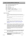
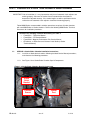
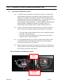
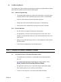
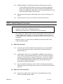
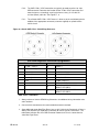
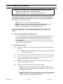
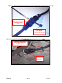
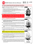
5.2.2:
The SAE J1708 / J1587 connection can typically be made near the 6 or 9 pin
OBD connector. Determine the location for the J1708 / J1587 connection and
route the harness accordingly securing the harness every 12-18” with UV
resistant (Black) cable ties. See Figures 7, 8.
5.2.1:
The e-Stroke SAE J1708 / J1587 harness is blunt cut at the end allowing for the
addition of the appropriate connector (customer supplied) or spliced into the
vehicle circuit.
Figure 8: e-Stroke SAE J1708 / J1939 Wiring Reference
SAE OBD Diagnostic Connector Designations
6-Pin Connector
9-Pin Connector
A
J1708 / J1587(+)
A
Power (-)
B
J1708 / J1587(-)
B
Power (+)
C
Power (+)
C
CAN J1939 HI (+)
D
N/A
D
CAN J1939 LO (-)
E
Power (-)
E
CAN J1939 Shield
F
N/A
F
J1708 / J1587 (+)
G
J1708 / J1587 (-)
CAN J1939 HI (+) CHASSIS
NEW FLYER ONLY
CAN J1939 LO (-)CHASSIS
NEW FLYER ONLY
H
J
SAE J1939 / J1708 Notes:
1. Always reference Vehicle OEM Wiring Schematics for additional wiring information: wire
color, locations.
2. Consult vehicle manufacturer for recommended connection methods.
3. Some 2009 and newer New Flyer Buses have a split J1939 circuit, Powertrain & Chassis.
Always consult New Flyer OEM wiring schematic for vehicle specific connections. The
table above indicates the 9-Pin OBD connector Powertrain & Chassis connections for
some New Flyer Buses.
EB 08-003
rev. 02
11 of 16