1
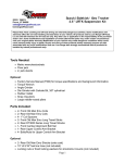
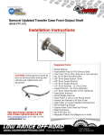
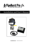
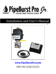
Instructions Created by an:
86-88.5 Suzuki Samurai Proportioning Valve Kit
(SKU# SB-PPV1)
Installation Instructions
CAUTION: Safety glasses should be
worn at all times when working with
vehicles and related tools and
equipment.
Suggested Tools:
•
•
•
•
•
•
•
•
For additional copies of these
and other instructions go to:
www.lowrangeoffroad and click on the
“Instructions” tab.
Tubing Wrench: 10mm
Socket: 10 mm
Ratchet
Combination Wrench: 3/8,7/16 & 1/2
Brake Fluid, DOT 3
PB Blaster
Twin Post Lift (Optional)
Floor Jack and (4) Jack Stands (Optional)
A word about Brake Fluid
3
2
1. Brake fluid will tarnish and in
some cases remove paint. If
brake fluid should accidentally
come in contact with painted
surfaces, flush immediately with
clean water.
2.
Brake fluid can absorb moisture
from the air. Moisture can lower
the boiling point of the brake fluid
and cause critical internal brake
components to rust. For these
reasons you should keep the
container closed when not
pouring from it. Further, to insure
you are using good, clean,
contaminate free brake fluid,
always use fluid from a sealed
container.
3. Always use the manufacturer
recommend brake fluid. Suzuki
recommends using DOT 3 Brake
Fluid in their Samurai’s and
Sidekicks.
4
5
1
7
6
Qty
Number
Figure A
Description
1
1
Inlet Hard Line
1
2
PV Inlet Fitting
1
3
Proportioning Valve
1
4
PV Outlet Fitting
1
5
Outlet Hard Line
3
6
Metric Union
1
7
Metric Plug (not used
in this application
Step 1
Install and tighten the outlet fitting using
a 7/16” open end wrench.
Step 2
Install and tighten the inlet fitting in the
same way.
Step 3
Set up the rest of the proportioning
valve assembly as shown here. Leave
all these fittings loose for now and set
this assembly aside.
Step 4
Disconnect the front brake line using a
10 mm tubing wrench.
Caution: Brake fluid will leak out. You
may want to put a cloth or a pan
underneath the brake line fitting to catch
the drips.
Step 5
Carefully bend the brake line slightly
downward.
Caution: Do not kink the brake line.
Note: The corners of
these fittings are easily
rounded. Always use a
tubing (or flare nut)
wrench to loosen brake
lines the first time.
Step 6
Step 7
Position the proportioning valve
assembly as shown and connect the
brake line you disconnected earlier to
the metric union.
Connect the inlet hardline to the master
cylinder. Leave all fittings hand tight for
now.
Toward the
Existing
Brake Line
Toward
Master
Cylinder
Tech Tip 7
Be sure the inlet of the proportioning
valve is oriented toward the master
cylinder and the outlet is oriented toward
the brake line going toward the wheels.
Step 8
Position the proportioning valve as
shown here.
Tightening all the fittings.
Step 9
Tighten the fitting at the master cylinder
using a 10 mm metric tubing wrench.
Step 10
Hold the proportioning valve inlet fitting
with a 7/16” wrench and tighten the inlet
hard line fitting using a 3/8 open end
wrench.
Step 11
Step 12
Repeat Step 10 on the proportioning
valve outlet fitting.
Hold the metric union with a 1/2” open
end wrench and tighten the fitting with a
10 mm open end wrench.
Step 13
Tech Tip 13
Repeat the previous step on the other
fitting connected to the metric coupler.
This is what the proportioning valve
assembly should look like when
finished.
Brake System Parts Identification
Proportioning
Valve
Right Rear
6 Way
Connector
Left Rear
Right Front
Left Front
Master
Cylinder
Figure B
Swapping Two Brake Lines at the 6 Way Connector.
This procedure converts the braking system from a “diagonal spit” braking system to a “frontrear split” system. Diagonal split means that one piston in the master cylinder controls the
Right Front and the Left Rear Wheels and the other piston controls the Left Front and the
Right Rear Wheels (See Figure C). After completing the procedures outlined below the
system will be a front-to-rear split braking system (See Figure D). Meaning one piston in the
master cylinder will control both front wheels and other piston will control both rear wheels.
Converting to a front-to-rear split system will allow for an adjustable proportioning valve to be
installed controlling the amount of braking done by the rear wheels.
Diagonal Split System
Forward
Figure C
Front-to-Rear Split System
Forward
Figure D
Lifting and Supporting the Vehicle
Tech Tip
Step 14 Optional
When working on suspension, brakes or
drive train parts it is a good idea to
spray all fasteners with penetrating oil a
day ahead. If not done a day ahead, an
hour or even minutes before is helpful.
Lift and support the vehicle on a twin
post lift.
Front
Floor Jack
Rear
Floor Jack
Note: We used a twin post lift, but this
job could also be done with a floor jack
and (4) safety stands. It is also possible
to do this job with the wheels on the
ground if you desire.
Step 15
Step 16
Remove the brake line shield by
removing the (2) bolts using a 10 mm
socket.
Set the shield aside.
Tech Tip 16
Step 17
Our objective is to swap these two brake
lines.
Note: This will allow the front brake line
of the master cylinder to control both
rear brakes and the rear brake line of the
master cylinder to control both front
brakes.
Disconnect these two lines from the 6
way connector using a 10mm tubing
wrench.
Note: Fluid will run out, so place a pan
under the fittings before you disconnect
them.
Step 18
Carefully bend each brake line and
reconnect them as shown here.
Caution: Be careful. If you try to make
a bend that is too sharp the tubing will
kink restricting flow of the fluid. Further,
once the brake line becomes kinked any
attempt to straighten it usually results in
breaking the brake line.
Step 20
Replace the brake line shield.
Caution: Be sure the shield does not
rub or contact the brake lines. Anything
that is in constant contact with the brake
lines can rub through, over time causing
a leak.
Step 19
Double check all the brake lines at the 6
way connection. Be sure all the fittings
are tight and the brake lines are routed
in a safe damage fee location.
Bypassing the OEM Proportioning Valve
Step 21
Loosen all four of the brake lines at the
proportioning valve using a 10mm
tubing wrench. (See Figure B for
proportioning valve location)
Step 22
Disconnect all four brake lines from the
proportioning valve.
Caution: These fittings can become
rusted or corroded. You may want to
spray them with a good penetrating
Step 23
Dismount the proportioning valve using
a 10mm socket.
Step 24
Remove the proportioning valve and set
it aside.
Note: This part will not be needed for
this install.
Step 25
Step 26
Carefully bend the (2) inlet brake lines
from a 90° angel to about a 45° angle
as shown.
Carefully bend the (2) outlet brake lines
from a 0° (or straight) angle to about a
45° angle as shown.
Step 27
Install the (2) supplied metric couplers
as shown.
Caution:
Do not cross-thread these
fittings.
You may need to bend the
brake lines a little more or less to get the
fittings to start threading properly.
Step 28
Hold the metric coupler using a 1/2”
wrench and tighten the fittings using a
10 mm tubing wrench.
Step 29
Tech Tip 29
Position the brake lines so that they do
not rub, get dented or damaged in any
way.
This is what they should look like when
completed.
Final Checks
Step 30
Step 31
Double check to see that all the fittings
are tight.
Double check all the brake line
connections at the master cylinder. Be
sure all the fittings are tight and the
brake lines are routed in a safe damage
fee environment.
Step 32
Bleed the brake system according
Suzuki Service Instructions.
Note: For detailed instructions on
bleeding Samurai brakes, go to
Click on
www.lowrangeoffroad.com.
Instructions/Samurai Instructions/
Samurai Brake System Bleed. Or click
HERE if you are viewing these
instructions via computer, tablet or
smart phone.
Important Note: Come back to
these instructions after
successfully bleeding the system.
You will need to adjust the
proportioning valve. See the
instructions on the next page.
Adjusting the Proportioning Valve
Step 33
1. Rotate proportioning valve dial counterclock-wise completely. This will fully
decrease rear brake pressure.
2. Check tires for proper tire pressure. Tires with improper tire pressure will
greatly effect this calibration procedure.
3. Locate an open dry hard surfaced parking lot (with no other vehicles around) to
perform this calibration procedure. Calibration procedure requires at least 2
people to perform (1 Driver, 1 Observer).
4. Drive vehicle slowly and apply brakes to ensure calipers are functioning. If
vehicle pulls hard in one direction when brakes are applied, calipers need
inspection. Do not perform this calibration procedure if calipers are not functioning
properly. Consult Suzuki service manual for inspection procedure.
5. In an open lot, drive vehicle 20 mph and apply brakes in an attempt to lock
tires. The Observer needs to watch behavior of tires outside the vehicle. When
braking, the Observer will see one of three possible situations:
! A) Front and rear tires lock simultaneously and equally.
! B) Front tires lock completely with rear tires slightly chirping (on the verge of
locking).
! C) Front tires not locking at all and rear locking completely.
6. Proper brake bias will result when situation B in step 5 is reached. If situation A
occurs, rotate proportioning valve dial clockwise 1/4 turn and repeat step 5. If
situation C occurs, rotate proportioning valve counterclockwise 1/4 turn and
repeat step 5. Although unlikely, if adjustment is necessary and no adjustment
is left in proportioning valve dial, contact Low Range Off-Road for assistance.
Congratulations!
You have finished the proportioning
valve installation.
We hope these
instructions have been helpful. If you
have suggestions how we could make
our instructions (or products better
please
email
us
at
[email protected].
As always, If you experience any difficulty during the installation of this product
please contact Low Range Off-Road Technical Support at 801-805-6644 M-F
7:30am-5:30pm MST. Thank you for purchasing from Low Range Off-Road.
These instructions are designed as a general installation guide. Installation of many Low Range
Off-Road products require specialized skills such as metal fabrication, welding and mechanical
trouble shooting. If you have any questions or are unsure about how to proceed, please contact
our shop at 801-805-6644 or seek help from a competent fabricator. Using fabrication tools such
as welders, torches and grinders can cause serious bodily harm and death. Please operate
equipment carefully and observe proper safety procedures.
Rock crawling and off-road driving are inherently dangerous activities. Some modifications will
adversely affect the on-road handling characteristics of your vehicle. All products sold by Low
Range Off-Road are sold for off road use only. Any other use or application is the responsibility
of the purchaser and/or user. Some modifications and installation of certain aftermarket parts may
under certain circumstances void your original dealer warranty. Modification of your vehicle may
create dangerous conditions, which could cause roll-overs resulting in serious bodily injury or
death. Buyers and users of these products hereby expressly assume all risks associated with any
such modifications and use.
Revised 05/12/14©
Copyright 2014 Low Range Off-Road, LC All Rights Reserved