1
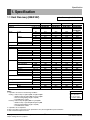
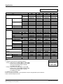
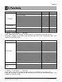
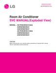
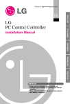
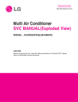
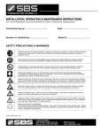
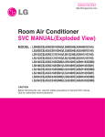
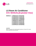
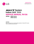
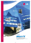
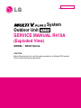
Internal Use Only
http://biz.lgservice.com
System
Outdoor Unit R410A
SERVICE MANUAL R410A
(Exploded View)
MODEL : ARUN Series
CAUTION
Before Servicing the unit, read the safety precautions in General SVC manual.
Only for authorized service personnel.
ARUN Series
1. Specifications ...............................................................................3
2. Function ........................................................................................5
3. Dimensions ...................................................................................6
4. Piping Diagrams ...........................................................................8
5. Wiring Diagrams .........................................................................13
6. Exploded View & Replacement Parts List................................16
Copyright ©2008 LG Electronics. Inc. All right reserved.
Only for training and service purposes
-2-
LGE Internal Use Only
Specification
1. Specification
1.1 Heat Recovery(208/230V)
HP(Equivalent horsepower)
Ton
Model Name
Capacity
Cooling
Heating
Input
Casing Color
Heat Exchanger
Compressor
Fan
Cooling
Heating
Type
Piston Displacement
Number of Revolution
Motor Output x Number
Starting Method
Oil Type
Oil Charge
Type
Motor Output x Number
Air Flow Rate(High)
Drive
Discharge
Pipe Connctions Liquid(flare)
Suction Gas
Discharge Gas
Dimensions (WxHxD)
Net Weight
Communication Cable
Refigerant
Refigerant name
Control
Power Supply
Heat Recovery(208/230V, 60Hz)
8
6.5
ARUB076BT2
ARUB076BT2
10
8.0
ARUB096BT2
ARUB096BT2
12
9.5
ARUB115BT2
ARUB115BT2
16
12.5
ARUB154BT2
Combination Unit
ARUB076BT2
Independent Unit
ARUB076BT2
22.4
28.0
33.6
44.8
kW
19,300
24,100
28,900
38,500
kcal/h
76,400
95,500
114,700
152,900
Btu/h
25.2
31.5
37.8
50.4
kW
21,700
27,100
32,500
43,300
kcal/h
86,000
107,500
129,000
172,000
Btu/h
6.20
7.8
10.8
12.40
kW
7.00
8.8
11.1
14.00
kW
Warm Gray
Warm Gray
Warm Gray
Warm Gray
Gold fin
Gold fin
Gold fin
Gold fin
DC Scroll
DC Scroll
DC Scroll
DC Scroll
38.3 + 59.8
38.3 + 59.8
38.3 + 59.8
(38.3 + 59.8)x2
cm3/rev
3,600 + 3,500
3,600 + 3,500
3,600 + 3,500
(3,600 + 3,500)x2
R.P.M
(4,130 + 5,280)x1 (4,130 + 5,280)x1 (4,130 + 5,280)x1 (4,130 + 5,280)x2
W
Direct On Line
Direct On Line
Direct On Line
Direct On Line
FVC68D(PVE)
FVC68D(PVE)
FVC68D(PVE)
FVC68D(PVE)
5,600
5,600
5,600
5,600x2
cc
Propeller fan
Propeller fan
Propeller fan
Propeller fan
350 x 2
350 x 2
350 x 2
350 x 4
W
190
190
190
380
CMM
6,700
6,700
6,700
13,400
cfm
DC INVERTER
DC INVERTER
DC INVERTER
DC INVERTER
TOP
TOP
TOP
TOP
Side / Top
9.52(3/8)
9.52(3/8)
12.7(1/2)
12.7(1/2)
mm(inch)
19.05(3/4)
22.2(7/8)
28.58(1 1/8)
28.58(1 1/8)
mm(inch)
15.88(5/8)
19.05(3/4)
19.05(3/4)
22.2(7/8)
mm(inch)
1,280x1,607x730
1,280x1,607x730
1,280x1,607x730
(1,280x1,607x730)x2
mm
50-3/8 x 63-5/16 x 28-11/16 50-3/8 x 63-5/16 x 28-11/16 50-3/8 x 63-5/16 x 28-11/16 (50-3/8 x 63-5/16 x 28-11/16)x2
inch
285
285
285
285+285
kg
628
628
628
628+628
lbs
CVV-SB 1.25x2C CVV-SB 1.25x2C CVV-SB 1.25x2C CVV-SB 1.25x2C
mm2
R410A
R410A
R410A
R410A
EEV
EEV
EEV
EEV
3, 208/230, 60
3, 208/230, 60
3, 208/230, 60
3, 208/230, 60
Ø, V, Hz
Notes:
1. Capacities are based on the following conditions:
Cooling * Indoor temp. 27°C[80.6°F]DB/ 19°C[66.2°F]WB
* Outdoor temp. 35°C[95°F]DB/ 24°C[75.2°F]WB
* Interconnecting Piping Length 7.5m(25ft)
* Level Difference of Zero
Heating * Indoor temp. 20°C[68°F]DB/ 15°C[59°F]WB
* Outdoor temp. 7°C[44.6°F]DB/ 6°C[42.8°F]WB
* Interconnecting Piping Length 7.5m(25ft)
* Level Difference of Zero
2. Capacities are net capacities
3. Due to our policy of innovation some specifications may be changed without prior notification
4. EEV : Electronic Expansion Valve
Copyright ©2008 LG Electronics. Inc. All right reserved.
Only for training and service purposes
-3-
Conversion Formula
kcal/h= kW x 860
Btu/h = kW x 3412
cfm = m3/min x 35.3
l/s = CMM x 1000/60
LGE Internal Use Only
Specification
Heat Recovery(208/230V, 60Hz)
HP(Equivalent horsepower)
Ton
Model Name
Capacity
Cooling
Heating
Input
Casing Color
Heat Exchanger
Compressor
Fan
Cooling
Heating
Type
Piston Displacement
Number of Revolution
Motor Output x Number
Starting Method
Oil Type
Oil Charge
Type
Motor Output x Number
Air Flow Rate(High)
Drive
Discharge
Pipe Connctions Liquid(flare)
Suction Gas
Discharge Gas
Dimensions (WxHxD)
Net Weight
Communication Cable
Refigerant
Refigerant name
Control
Power Supply
18
20
14.5
16.0
ARUB192BT2
Combination Unit ARUB173BT2
ARUB096BT2
Independent Unit ARUB096BT2
ARUB076BT2
ARUB096BT2
50.4
56.0
kW
43,300
48,200
kcal/h
172,000
191,100
Btu/h
56.7
63.0
kW
48,800
54,200
kcal/h
193,500
225,000
Btu/h
14.00
15.60
kW
15.80
17.60
kW
Warm Gray
Warm Gray
Gold fin
Gold fin
DC Scroll
DC Scroll
(38.3 + 59.8)x2
(38.3 + 59.8)x2
cm3/rev
(3,600+3,500)x2 (3,600+3,500)x2
R.P.M
(4,130 + 5,280)x2 (4,130 + 5,280)x2
W
Direct On Line
Direct On Line
FVC68D(PVE)
FVC68D(PVE)
5,600x2
5,600x2
cc
Propeller fan
Propeller fan
350 x 4
350 x 4
W
380
380
CMM
13,400
13,400
cfm
DC INVERTER
DC INVERTER
TOP
TOP
Side / Top
15.88(5/8)
15.88(5/8)
mm(inch)
28.58(1 1/8)
28.58(1 1/8)
mm(inch)
22.2(7/8)
22.2(7/8)
mm(inch)
(1,280x1,607x730)x2 (1,280x1,607x730)x2
mm
(50-3/8 x 63-5/16 x 28-11/16)x2 (50-3/8 x 63-5/16 x 28-11/16)x2
inch
285+285
285+285
kg
628+628
628+628
lbs
CVV-SB 1.25x2C CVV-SB 1.25x2C
mm2
R410A
R410A
EEV
EEV
3, 208/230, 60
3, 208/230, 60
Ø, V, Hz
22
17.5
ARUB211BT2
ARUB115BT2
ARUB096BT2
61.6
53,000
210,200
69.3
59,600
236,500
18.60
19.90
Warm Gray
Gold fin
DC Scroll
(38.3 + 59.8)x2
(3,600+3,500)x2
(4,130 + 5,280)x2
Direct On Line
FVC68D(PVE)
5,600x2
Propeller fan
350 x 4
380
13,400
DC INVERTER
TOP
15.88(5/8)
34.9(1 3/8)
28.58(1 1/8)
(1,280x1,607x730)x2
(50-3/8 x 63-5/16 x 28-11/16)x2
285+285
628+628
CVV-SB 1.25x2C
R410A
EEV
3, 208/230, 60
Notes:
1. Capacities are based on the following conditions:
Cooling * Indoor temp. 27°C[80.6°F]DB/ 19°C[66.2°F]WB
* Outdoor temp. 35°C[95°F]DB/ 24°C[75.2°F]WB
* Interconnecting Piping Length 7.5m(25ft)
* Level Difference of Zero
Heating * Indoor temp. 20°C[68°F]DB/ 15°C[59°F]WB
* Outdoor temp. 7°C[44.6°F]DB/ 6°C[42.8°F]WB
* Interconnecting Piping Length 7.5m(25ft)
* Level Difference of Zero
2. Capacities are net capacities
3. Due to our policy of innovation some specifications may be changed without prior notification
4. EEV : Electronic Expansion Valve
Copyright ©2008 LG Electronics. Inc. All right reserved.
Only for training and service purposes
-4-
24
19.0
ARUB230BT2
ARUB115BT2
ARUB115BT2
67.2
57,800
229,300
75.6
65,000
258,000
21.60
22.20
Warm Gray
Gold fin
DC Scroll
(38.3 + 59.8)x2
(3,600+3,500)x2
(4,130 + 5,280)x2
Direct On Line
FVC68D(PVE)
5,600x2
Propeller fan
350 x 4
380
13,400
DC INVERTER
TOP
15.88(5/8)
34.9(1 3/8)
28.58(1 1/8)
(1,280x1,607x730)x2
(50-3/8 x 63-5/16 x 28-11/16)x2
285+285
628+628
CVV-SB 1.25x2C
R410A
EEV
3, 208/230, 60
Conversion Formula
kcal/h= kW x 860
Btu/h = kW x 3412
cfm = m3/min x 35.3
l/s = CMM x 1000/60
LGE Internal Use Only
Functions
2. Functions
Category
Reliability
Convenience
CAC network
Function
Other
Function
Defrost/ Deicing
High pressure switch
Low pressure switch
Phase protection
Restart delay(3-minutes)
Self diagnosis
Soft start
Trial operation
Auto operation(Artificial intelligence)
Auto restart operation
Network Solution(LGAP)
Power Distribution Indicator(PNU-D1S00)
Thermistor
Single Unit
Series Unit
O
O
O
O
O
O
O
O
O
O
O
O
-
O
O
O
O
O
O
O
O
O
O
O
O
-
O : Applied
X : Not applied
- : No reation
Option : Model name & price are different according to options, and assembled in factory with main unit
Accessory : Installed at field, ordered and purchased separately by the corresponding model name,
supplied with separated package.
Category
CAC Network
Program
Other
Device
Network Solution(LGAP)
Simple Central Controller
Function Controller
PC Central control Software
Deluxe Central Controller
Power Distribution Indicator(PDI)
CNU2(I-Gataway)
Dry contact(Outdoor Unit)
Dry contact(Indoor Unit)
AC Smart
ACP
AC Manager
LONWORKS Gateway (BNU-LW)
BACnet Gateway (BNU-BN)
LG MV
Y branch
Header branch
Air Guide
Super II
O
PQCSB101S0
PQCSC101S0
PQCSS513A0
PQCSW502A2
PQNUD1S00
PQNFG14B0
PRDSBM
PQDSB
PQCSW320A0E
PQCPA11A0E/B11A0E
PQCSS520A0E
PQNFB16A1
PQNFB17B0
Option
Accessory
Accessory
Accessory
O : Applied
X : Not applied
- : No reation
Option : Model name & price are different according to options, and assembled in factory with main unit
Accessory : Installed at field, ordered and purchased separately by the corresponding model name,
supplied with separated package.
Copyright ©2008 LG Electronics. Inc. All right reserved.
Only for training and service purposes
-5-
LGE Internal Use Only
L3
L5
D
H
Copyright ©2008 LG Electronics. Inc. All right reserved.
Only for training and service purposes
W
L4
L6
-6160(6-5/16)
60(2-3/8)
LG Electronics USA, HVAC Division
1000 Sylvan Avenue, Englewood Cliffs, NJ 07632
www.lgusa.com / www.lghvac.com
L7
L1
D
mm(inch)
mm(inch)
mm(inch)
mm(inch)
mm(inch)
mm(inch)
mm(inch)
mm(inch)
D
L1
L2
L3
L4
L5
L6
L7
82(3-3/16)
99(3-7/8)
704(27-11/16)
900(35-3/8)
670(26-5/16)
692(27-3/16)
1427(56-1/8)
730(28-11/16)
1607(63-5/16)
1280(50-3/8)
CHASSIS CODE: UW1
mm(inch)
H
76, Seongsan-dong, Changwon City, Gyeongnam,
641-713, Korea
www.lgeaircon.com
mm(inch)
W
[Unit: mm(inch)]
ARUB076BT2
ARUB096BT2
ARUB115BT2
Outdoor Unit(208/230V)
Dimensions
3. Dimensions
LGE Internal Use Only
L2
L3
L6
L2
D
Front side
250mm(9-13/16 inch) or more
60(2-3/8)
900mm(35-7/16 inch)
or more
250mm
(9-13/16 inch)
or more
L8
160(6-5/16)
LG Electronics USA, HVAC Division
1000 Sylvan Avenue, Englewood Cliffs, NJ 07632
www.lgusa.com / www.lghvac.com
Front side:1500mm(59-1/16 inch), Suction side:500mm(19-11/16 inch)
2. If the above wall heights are exceeded, then h1/2 and h2/2 should be added to the front and
suction side service spaces respectively as shown in the following figure.
3. When installing the units, the most appropriate pattern should be selected from those shown.
In order to obtain the best fit in the space available, always bear in mind the need to leave
enough room for a person to pass between units and wall and for the air to circulate freely.
Your layout should take into account the possibility of short circuits.
4. The Units should be installed to leave sufficient space in front for the on site refrigerant piping
work to be carried out comfortably.
L7
L1
D
H
Notes:
1. Height of walls in case of pattern1:
W
L5
1500mm(59-1/16 inch) h2
L4
Front side
-7Suction side
Copyright ©2008 LG Electronics. Inc. All right reserved.
Only for training and service purposes
250mm
(9-13/16 inch)
or more
W
H
D
L1
L2
L3
L4
L5
L6
L7
L8
CHASSIS CODE: UW1
82(3-3/16)
99(3-7/8)
704(27-11/16)
10(3/8)
900(35-3/8)
670(26-5/16)
692(27-3/16)
1427(56-1/8)
730(28-11/16)
1607(63-5/16)
1280(50-3/8)
[Unit: mm(inch)]
ARUB154BT2
ARUB173BT2
ARUB192BT2
ARUB211BT2
ARUB230BT2
mm(inch)
mm(inch)
mm(inch)
mm(inch)
mm(inch)
mm(inch)
mm(inch)
mm(inch)
mm(inch)
mm(inch)
mm(inch)
76, Seongsan-dong, Changwon City, Gyeongnam,
641-713, Korea
www.lgeaircon.com
500mm h1
(19-11/16 inch)
Outdoor Unit(208/230V)
Dimensions
LGE Internal Use Only
Piping Diagrams
4. Piping Diagrams
4.1 Heat Pump Model
4.1.1 ARUB076BT2, ARUB096BT2, ARUB115BT2
Cooling Operation
: Low temp./Low pressure gas
: High temp./High pressure liquid
: High temp./High pressure gas
Indoor unit
Heat Exch.
EEV
Fan
HR unit
Filter
s
s
s
Indoor unit
s
s
Filter
s
s
s
Indoor unit
Heat Exch.
EEV
Fan
s
s
Indoor unit
Heat Exch.
EEV
Fan
s
Filter
s
Fan
EEV
s
Heat Exch.
Filter
s
Hot Gas
By pass
4 Way Valve
High Pressure Gas Pipe
Low Pressure Gas Pipe
Liquid Pipe
O/S
O/S
s
(Low pressure Gas Pipe)
s
(Liquid pipe)
Liquid Injection
CON
Comp
(High pressure Gas Pipe)
Accum
s
INV
Comp
Sub-Cooler
Outdoor unit
Pressure sensor
Pressure switch
s
Check valve
EEV
Service Valve
Sensor
Strainer
Solenoid
Copyright ©2008 LG Electronics. Inc. All right reserved.
Only for training and service purposes
*(
-8-
) To be used only for series
LGE Internal Use Only
Piping Diagrams
Heating Operation
: Low temp./Low pressure gas
: High temp./High pressure liquid
: High temp./High pressure gas
Indoor unit
Heat Exch.
EEV
Fan
Filter
HR unit
s
s
s
Filter
s
Fan
s
s
s
EEV
s
s
s
Indoor unit
Heat Exch.
s
s
Indoor unit
Heat Exch.
EEV
Fan
Filter
Fan
s
Indoor unit
Heat Exch.
EEV
Filter
s
Hot Gas
By pass
4 Way Valve
High Pressure Gas Pipe
Low Pressure Gas Pipe
Liquid Pipe
O/S
O/S
s
s
(Low pressure Gas Pipe)
s
Liquid Injection
(Liquid pipe)
CON
Comp
Accum
(High pressure Gas Pipe)
INV
Comp
Sub-Cooler
Outdoor unit
Pressure sensor
EEV
Service Valve
Pressure switch
Sensor
Strainer
s
Check valve
Solenoid
Copyright ©2008 LG Electronics. Inc. All right reserved.
Only for training and service purposes
*( ) To be used only for series
-9-
LGE Internal Use Only
Piping Diagrams
Oil Return/ Defrost Operation
: Low temp./Low pressure gas
: High temp./High pressure liquid
: High temp./High pressure gas
Indoor unit
Heat Exch.
EEV
Fan
HR unit
Filter
s
s
s
Indoor unit
s
s
Filter
s
s
s
Indoor unit
Heat Exch.
EEV
Fan
s
s
Indoor unit
Heat Exch.
EEV
Fan
s
Filter
s
Fan
EEV
s
Heat Exch.
Filter
s
Hot Gas
By pass
4 Way Valve
High Pressure Gas Pipe
Low Pressure Gas Pipe
Liquid Pipe
O/S
O/S
s
(Low pressure Gas Pipe)
s
(Liquid pipe)
Liquid Injection
CON
Comp
(High pressure Gas Pipe)
Accum
s
INV
Comp
Sub-Cooler
Outdoor unit
Pressure sensor
EEV
Service Valve
Pressure switch
Sensor
Strainer
s
Check valve
Solenoid
Copyright ©2008 LG Electronics. Inc. All right reserved.
Only for training and service purposes
*(
- 10 -
) To be used only for series
LGE Internal Use Only
Piping Diagrams
Simultaneous Operation Mode 1 (Cooling Based operation)
: Low temp./Low pressure gas
: High temp./High pressure liquid
: High temp./High pressure gas
Indoor unit
Cooling
"ON"
Heat Exch.
EEV
Fan
Filter
HR unit
s
s
s
Filter
s
Fan
s
s
s
Cooling
"ON"
EEV
s
s
s
Indoor unit
Heat Exch.
s
s
Indoor unit
Cooling
"ON"
Heat Exch.
EEV
Fan
Filter
s
Indoor unit
Heat Exch.
EEV
Fan
Filter
Heating
"ON"
s
Hot Gas
By pass
4 Way Valve
High Pressure Gas Pipe
Low Pressure Gas Pipe
Liquid Pipe
O/S
O/S
Pressure sensor
Pressure switch
INV
Comp
CON
Comp
Accum
Check valve
s
EEV
s
s
Liquid Injection
Sensor
s
Sub-Cooler
Service Valve
Outdoor unit
Copyright ©2008 LG Electronics. Inc. All right reserved.
Only for training and service purposes
Solenoid
- 11 -
Strainer
LGE Internal Use Only
Piping Diagrams
Simultaneous Operation Mode 2 (Heating Based operation)
: Low temp./Low pressure gas
: High temp./High pressure liquid
: High temp./High pressure gas
Indoor unit
Heating
"ON"
Heat Exch.
EEV
Fan
Filter
HR unit
s
s
s
Fan
Filter
s
EEV
s
s
s
Heating
"ON"
s
s
s
Indoor unit
Heat Exch.
s
s
Indoor unit
Heating
"ON"
Heat Exch.
EEV
Fan
Filter
Cooling
"ON"
s
Indoor unit
Heat Exch.
EEV
Fan
Filter
s
Hot Gas
High Pressure Gas Pipe
Bypass
4 Way Valve
Low Pressure Gas Pipe
Liquid Pipe
O/S
O/S
Pressure sensor
Pressure switch
INV
Comp
CON
Comp
Accum
Check valve
s
EEV
s
s
Liquid Injection
Sensor
s
Sub-Cooler
Service Valve
Outdoor unit
Copyright ©2008 LG Electronics. Inc. All right reserved.
Only for training and service purposes
Solenoid
- 12 -
Strainer
LGE Internal Use Only
Wiring Diagrams
5. Wiring Diagrams
5.1 Heat Pump Model
3Ø 208/230V 3N
60Hz
5.1.1 3Ø 208/230V(ARUB076BT2, ARUB096BT2, ARUB115BT2)
Copyright ©2008 LG Electronics. Inc. All right reserved.
Only for training and service purposes
- 13 -
LGE Internal Use Only
Wiring Diagrams
■ Main PCB
CN29 TO INVERTER BOARD
SW01S RESET
( INVERTER PCB COMMUNICATION TERMINAL)
(RESET BUTTON)
CN38 EEV-OUT
CN04 FLASH_WRITE
( OUTDOOR ELECTRONIC EXPANSION VALVE)
(ONBOARDING TERMINAL)
CN40 EEV-SC
CN05 TO JIG
( SUBCOOLING CIRCUIT ELECTRONIC EXPANSION VALVE)
(JIG CONNECTION TERMINAL: LGMV)
CN44 P(I) S/W
SW02V AUTO ADDRES
( INV COMP HIGH PRESSUR SWITCH))
(AUTO ADDRESSING SWITCH)
CN41 CEN CONTROL
CN43 P(C) S/W
(CENTRAL CONTROL TERMINAL)
( CONSTANT COMP HIGH
PRESSURE SWITCH)
CN33
CN17 LIQ(C)
SC-OUT
( CONSTANT COMP LIQUID VALVE
(SC CIRCUIT OUTLET TEMP SENSOR)
CN16 LIQ(I)
SC-IN
( INVERTER COMP LIQUID VALVE
(SC CIRCUIT INTLET TEMP SENSOR)
SUCTION
CN15 AC FAN
(SUCTION TEMPERATURE SENSOR)
( AC FAN POWER SUPPLY)
CN34
CN14 MAGNET(C)
DISCHARGE(I)
( CONSTANT COMP MAGNETIC
SWITCH)
(INV DISCHARGE TEMP SENSOR)
CN13 HOT GAS
HEX1
( HOT GAS SOLENOID VALVE)
(OUTDOOR HEX TEMP SENSOR 1)
HEX2
CN11 HEATER(C)
(OUTDOOR HEX TEMP SENSOR 2)
( CONSTANT COMP HEATER)
CN35
CN10 HEATER(I)
( INVERTER COMP HEATER)
AIR
(OUTDOOR TEMPERATURE SENSOR)
CN09 4WAY
SUCTION
(4 WAY REVERSING VALVE)
(SUCTION TEMPERATURE SENSOR)
CN08 AC 220 V
(220 V POWER INPUT TERMINAL)
JIG1, JIG2
( JIG POWER TERMINAL : AC 220V)
Copyright ©2008 LG Electronics. Inc. All right reserved.
Only for training and service purposes
CN27 STD_COMP CT1
(CONSTANT COMP CURRENT SENSOR)
CN32 P-SENSOR(L)
(LOW PRESSURE SENSOR)
- 14 -
DISCHARGE(C)
(CONST COMP DISCHARGE
TEMP SENSOR)
CN30 P-SENSOR(H)
(HIGH PRESSURE SENSOR)
LGE Internal Use Only
Wiring Diagrams
■ FAN PCB(UW1)
■ Noize Filter
CN_MICOM WRITING
INV Onboarding Terminal
CN FAN RIGHT
Left Fan Motor Hall Sensor
CN DC LINK
700V DC LINK
CN HEAT SINK
Heat Sink Temp. Sensor
CN INV_COM
Communication Terminal to
INV PCB
CN FAN LEFT
Right Fan Motor Hall Sensor
CN 15V
DC 15V Power Input Terminal
CN HALL SENSOR(R)
Left Fan Motor Hall Sensor
CN HALL SENSOR(L)
Right Fan Motor Hall Sensor
TO MAIN PCB
220V Power Output Terminal
TO INV. PCB
220V Power Output Terminal
■ Inveter PCB (3Ø 208/230V)
CN_06AC220V INPUT
220V Power Input Terminal
CN12 DC_LINK(700V)
(700V DC LINK)
CN13 15V OUTPUT
DC 15V Output Terminal
CN_L1(R)
R Phase Terminal
CN04 PFC LGMV
PFC Onboarding Terminal
CN_L2(S)
S Phase Terminal
CN_L3(T)
T Phase Terminal
CN14 UVW OUT
UVW Output Terminal
CN-FLASH WRITE(INV)
CN-FLASH WRITE(PFC)
CN03 INV LGMV
INV Onboarding Terminal
CN05 COOLING FAN
CN02 Main
Communication Terminal to Main PCB
Copyright ©2008 LG Electronics. Inc. All right reserved.
Only for training and service purposes
CN01 FAN
Communication Terminal to Fan PCB
- 15 -
LGE Internal Use Only
Explodede View
6. Exploded View
Outdoor Unit
UW1 Chassis (208/230V, ARUB076BT2/096BT2/115BT2)
268711C
268711A
268711B
649950A
566001
649950B
W6631A
Copyright ©2008 LG Electronics. Inc. All right reserved.
Only for training and service purposes
W6200
- 16 -
W6640
W6631B
LGE Internal Use Only
Explodede View
435512
554030B
552115C
W5210B
137213A
554030D
435312
552115D
352114B
559010
352111B
546810
349600
559010
546810
263230B
554030A
552115B
W5210B
263230C
554030C
346811
552115A
352114A
137213B
437212
649950A
552204A
352111B
552204B
649950B
561410D
561410B
435310
552204
165010B
552201B
566000
561410A
W52240B
552204A
561410C
165010A
552202
55211G
235042
W52240E
552102
552201A
W52240D
552201A
554160A
548490
553000A
437211
566000B
W52240A
352111A
263230A 55211F
W52240A
554160B
552102
552203C
552203B
553000B
552203A
THERMISTOR 1
THERMISTOR 2
THERMISTOR 3
263230A
263230B
263230C
Liquid Pipe + sub Cooler IN + Sub Cooler OUT
Inv. discharge + HEX(Front) + HEX (back)
Air + suction Pipe
Copyright ©2008 LG Electronics. Inc. All right reserved.
Only for training and service purposes
- 17 -
Housing color : yellow
Housing color : purple
Housing color : black
LGE Internal Use Only
P/NO : MFL54555502
JUNE, 2008