1
TPA6011A4
SLOS392 – FEBRUARY 2002
APPLICATION INFORMATION
input resistance
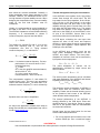
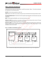
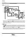
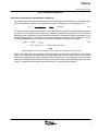
Each gain setting is achieved by varying the input resistance of the amplifier, which can range from its smallest
value to over six times that value. As a result, if a single capacitor is used in the input high-pass filter, the –3 dB
or cutoff frequency also changes by over six times. If an additional resistor is connected from the input pin of
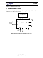
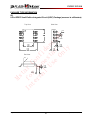
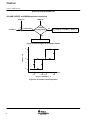
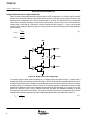
the amplifier to ground, as shown in the figure below, the variation of the cutoff frequency is much reduced.
Rf
C
Ri
IN
Input Signal
Figure 34. Resistor on Input for Cut-Off Frequency
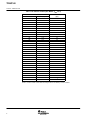
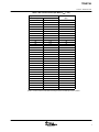
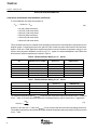
The input resistance at each gain setting is given in Figure 34.
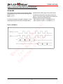
The –3-dB frequency can be calculated using equation 1.
ƒ *3 dB +
1
2p CR
(1)
i
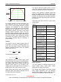
input capacitor, Ci
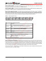
In the typical application an input capacitor (Ci) is required to allow the amplifier to bias the input signal to the
proper dc level for optimum operation. In this case, Ci and the input impedance of the amplifier (Ri) form a
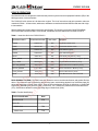
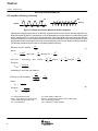
high-pass filter with the corner frequency determined in equation 2.
–3 dB
f c(highpass) +
(2)
1
2 p Ri Ci
fc
www.ti.com
23