1
AIR CONDITIONING 18-3
+
high-side pressure of approximately 2700 kPa (430 psi
20
psi) and reclose the circuit at approximately 1379 kPaT2OO
psi
50 psi).
Low-Pressure Cut-Off Switch
Compressor protection is provided on some-cars by a
low-pressure cut-off switch which will open in the event of
a low-charge condition.
compressor cycling during engine idle for a predetermined
time after the vehicle has come to rest from road speed. If
the idle period continues for an extended time, the A/C
system may return to a conventional C.C.O.T. mode for a
short time to prevent system freeze-up. The A/C control
relay and constant run relays are both controlled by the
Electronic Control Module (ECM) which determines
operating conditions by evaluating input from the
distributor (engine speed), vehicle speed sensor, air sensor
and A/C compressor "on" signal.
Pressure Cycling Switch
The refrigeration cycle (on and off operation of the
compressor) is controlled by a switch which senses the
low-side pressure as an indicator of evaporator temperature.
The pressure cycling switch is the freeze protection device
in the system and senses refrigerant pressure on the suction
side of the system. This switch is located on a standard
Schrader-type valve low-side fitting.
Additional compressor protection results from the
operating characteristics of the low-side pressure cycling
system. If a massive discharge occurs in the low side of the
system or the orifice tube becomes plugged, low-side
pressures could be insufficient to close the contacts of the
pressure switch. In the event of a low charge, insufficient
cooling accompanied by rapid compressor clutch cycling
will be noticed at high air temperatures.
Power Steering Cut-Off Switch
Engine idle quality on some cars is maintained by
cutting off the compressor when high power steering loads
are imposed.
W ide-Open Throttle (WOT) Compressor Cut-Out
Switch
A switch located on the accelerator pedal assembly of
vehicles with automatic transmission opens the circuit to the
compressor clutch during full throttle acceleration. The
switch activates a relay that controls the compressor clutch.
A pressure sensitive switch located in the transmission
overrides the compressor cut-out switch if the transmission
is in high gear when full throttle acceleration is called for.
Air Conditioning Time Delay Relay
This relay on some cars controls the current to the
entire air conditioning system and provides a short delay of
air conditioning operation upon start up. Whenever the air
conditioning system is operating, current is also applied to
the idle stop solenoid (automatic transmissions only) to
increase engine idle speed. The relay is controlled by the
engine temperature (Hot Light) switch. When the engine
temperature switch makes contact, the relay interrupts
current to the A/C system and holds the system off while
the switch is closed. When the engine temperature switch
closes, a short time delay is provided to prevent the relay
from responding to brief closures of the switch, thereby
preventing compressor clutch chatter.
Compressor Control Relay
The compressor on some cars is cut off under certain
other engine operating conditions by one or more A/C
control relays; wide-open throttle, low air temperature,
engine overheat and low engine speed.
Constant Run Relay
Engine idle quality on some cars is maintained by a
"constant run" system (constant run relay) that eliminates
Air Temperature Sensor
An air temperature sensor is used on some cars to
prevent compressor operation below a specific air
temperature when compressor damage could occur.
DIAGNOSIS
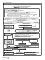
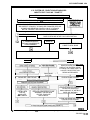
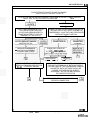
TESTING THE REFRIGERANT SYSTEM
If a malfunction in the refrigerant system is suspected
due to abnormal system pressures, check the following:
1. Check outer surfaces of radiator and condenser cores
to be sure air flow is not blocked by.dirt, leaves or
other foreign material. Be sure to check between the
condenser and radiator as well as the outer surfaces.
2. Restrictions or kinks in evaporator core or condenser
core, hoses, tubes, etc.
3. Refrigerant leaks.
4. Check all air ducts for leaks or restrictions. Low air
flow rate may indicate a restricted evaporator core.
5 . Compressor clutch slippage.
6. Improper drive belt tension.
7. Plugged accumulator or expansion (orifice) tube.
8. Excessive moisture in refrigerant system.
LEAK TESTING THE REFRIGERANT SYSTEM
Whenever a refrigerant leak is suspected in the system
or a service operation performed which results in disturbing
lines or connections, it is advisable to test for leaks. Liquid
Leak Detectors
There are a number of locations (fittings, valves, etc.)
on the air conditioning system where a liquid leak detector
solution may be used to pinpoint refrigerant leaks.
By applying test solution to the area in question with
the swab that is attached to the bottle cap, bubbles will form
within seconds if there is a leak.
For restricted access areas, such as sections of the
evaporator and condenser, an electronic leak detector, such
as 5-23400 or equivalent, is more practical for determining
and locating leaks.
RED DYE LEAK DETECTOR
All Series
Some vehicles with factory-installed air conditioning
are charged with a red dye leak detector. A bright red color
(usually oil) will appear at the point of leakage. The dye is
mixable both in the liquid R-12 and in the compressor oil.
The dye leaves the compressor in the oil which is carried
along with hot R-12 discharge gas. In the condenser, the dye
and the oil are dissolved in the liquid R-12. The resulting
mixture usually has a faint pink color. The darkness or
lightness of the color depends upon the oil moving through
the compressor. Leak detection in the condenser and liquid
line may be slower due to the low amount of red dye in the
oil. In the evaporator when the R-12 flashed to a gas the dye
remains in the oil. It is then returned to the compressor by