1
Electromagnetic Inductive RFID System
V670 Series
User's Manual
CF Reader/Writer
V670-CF01
ID Tag
V670-D13F03
V670-D13F01
V670-D13F01H
Cat. No. Z204-E1-02
Standard Conformity (Be sure to read.)
SECTION 1
Product Outline
SECTION 2
Communications Preparations
SECTION 3
Functions
SECTION 4
Commands
SECTION 5
Troubleshooting
SECTION 5
SECTION 6
Appendices (Specifications and Dimensions, Characteristics Data Based on
Operating Conditions, Memory Map, Maintenance and Inspection,
Table of JIS8 Unit Code (ASCII), Degree of Protection)
SECTION 6
SECTION
ÇÕǹÇ?Ç
Introduction ëÊ
1 èÕ1 ëÊ
SECTION
2 èÕ2 ëÊ
SECTION
3 èÕ3 ëÊ
SECTION
4 èÕ4
Introduction
Electromagnetic Inductive RFID System
V670-CF01
V670-D13F03
V670-D13F01
V670-D13F01H
CF Reader/Writer
ID Tag
ID Tag
ID Tag
User's Manual
Introduction
Introduction
Introduction
OMRON products are manufactured for use according to proper procedures by a qualified operator and only for the
Introduction
purposes described in this manual. Observe the following precautions when using a V670-series Electromagnetic
Inductive RFID System.
• Read and understand this manual before attempting to use the product and use the product correctly.
• Keep this manual in a safe but accessible location so that it can be used as reference when required.
READ AND UNDERSTAND THIS DOCUMENT
Please read and understand this document before using the products. Please consult your OMRON representative if you have any questions or comments.
WARRANTY
OMRON’s exclusive warranty is that the products are free from defects in materials and workmanship for a period of one year (or other period if specified)
from date of sale by OMRON.
OMRON MAKES NO WARRANTY OR REPRESENTATION, EXPRESS OR IMPLIED, REGARDING NON-INFRINGEMENT, MERCHANTABILITY, OR
FITNESS FOR PARTICULAR PURPOSE OF THE PRODUCTS. ANY BUYER OR USER ACKNOWLEDGES THAT THE BUYER OR USER ALONE HAS
DETERMINED THAT THE PRODUCTS WILL SUITABLY MEET THE REQUIREMENTS OF THEIR INTENDED USE. OMRON DISCLAIMS ALL OTHER
WARRANTIES, EXPRESS OR IMPLIED.
LIMITATIONS OF LIABILITY
OMRON SHALL NOT BE RESPONSIBLE FOR SPECIAL, INDIRECT, OR CONSEQUENTIAL DAMAGES, LOSS OF PROFITS OR COMMERCIAL LOSS
IN ANY WAY CONNECTED WITH THE PRODUCTS, WHETHER SUCH CLAIM IS BASED ON CONTRACT, WARRANTY, NEGLIGENCE, OR STRICT
LIABILITY.
In no event shall responsibility of OMRON for any act exceed the individual price of the product on which liability is asserted.
IN NO EVENT SHALL OMRON BE RESPONSIBLE FOR WARRANTY, REPAIR, OR OTHER CLAIMS REGARDING THE PRODUCTS UNLESS OMRON’S
ANALYSIS CONFIRMS THAT THE PRODUCTS WERE PROPERLY HANDLED, STORED, INSTALLED, AND MAINTAINED AND NOT SUBJECT TO
CONTAMINATION, ABUSE, MISUSE, OR INAPPROPRIATE MODIFICATION OR REPAIR.
SUITABILITY FOR USE
THE PRODUCTS CONTAINED IN THIS DOCUMENT ARE NOT SAFETY RATED. THEY ARE NOT DESIGNED OR RATED FOR ENSURING SAFETY OF
PERSONS, AND SHOULD NOT BE RELIED UPON AS A SAFETY COMPONENT OR PROTECTIVE DEVICE FOR SUCH PURPOSES. Please refer to
separate catalogs for OMRON's safety rated products.
OMRON shall not be responsible for conformity with any standards, codes, or regulations that apply to the combination of products in the customer’s
application or use of the product.
At the customer’s request, OMRON will provide applicable third party certification documents identifying ratings and limitations of use that apply to the
products. This information by itself is not sufficient for a complete determination of the suitability of the products in combination with the end product,
machine, system, or other application or use.
The following are some examples of applications for which particular attention must be given. This is not intended to be an exhaustive list of all possible uses
of the products, nor is it intended to imply that the uses listed may be suitable for the products:
• Outdoor use, uses involving potential chemical contamination or electrical interference, or conditions or uses not described in this document.
• Nuclear energy control systems, combustion systems, railroad systems, aviation systems, medical equipment, amusement machines, vehicles, safety
equipment, and installations subject to separate industry or government regulations.
• Systems, machines, and equipment that could present a risk to life or property.
Please know and observe all prohibitions of use applicable to the products.
NEVER USE THE PRODUCTS FOR AN APPLICATION INVOLVING SERIOUS RISK TO LIFE OR PROPERTY WITHOUT ENSURING THAT THE
SYSTEM AS A WHOLE HAS BEEN DESIGNED TO ADDRESS THE RISKS, AND THAT THE OMRON PRODUCT IS PROPERLY RATED AND
INSTALLED FOR THE INTENDED USE WITHIN THE OVERALL EQUIPMENT OR SYSTEM.
PERFORMANCE DATA
Performance data given in this document is provided as a guide for the user in determining suitability and does not constitute a warranty. It may represent the
result of OMRON’s test conditions, and the users must correlate it to actual application requirements. Actual performance is subject to the OMRON Warranty
and Limitations of Liability.
CHANGE IN SPECIFICATIONS
Product specifications and accessories may be changed at any time based on improvements and other reasons.
It is our practice to change model numbers when published ratings or features are changed, or when significant construction changes are made. However,
some specifications of the product may be changed without any notice. When in doubt, special model numbers may be assigned to fix or establish key
specifications for your application on your request. Please consult with your OMRON representative at any time to confirm actual specifications of purchased
products.
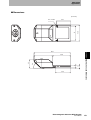
DIMENSIONS AND WEIGHTS
Dimensions and weights are nominal and are not to be used for manufacturing purposes, even when tolerances are shown.
ERRORS AND OMISSIONS
The information in this document has been carefully checked and is believed to be accurate; however, no responsibility is assumed for clerical, typographical,
or proofreading errors, or omissions.
PROGRAMMABLE PRODUCTS
OMRON shall not be responsible for the user’s programming of a programmable product, or any consequence thereof.
COPYRIGHT AND COPY PERMISSION
This document shall not be copied for sales or promotions without permission. This document is protected by copyright and is intended solely for use in
conjunction with the product. Please notify us before copying or reproducing this document in any manner, for any other purpose. If copying or transmitting
this document to another, please copy or transmit it in its entirety.
2
Electromagnetic Inductive RFID System
User's Manual
Introduction
Introduction
Standard Conformity
FCC NOTICE
This device complies with part 15 of the FCC Rules. Operation is subject to the following two conditions:
(1) This device may not cause harmful interference.
(2) This device must accept any interference received, including interference that may cause undesired operation.
FCC WARNING
Changes or modifications not expressly approved by the party responsible for compliance could void the user's authority to operate the equipment.
Standard Conformity
1. FCC Rules (Federal Communications Commission)
This product complies with Part 15 Subpart C of the FCC Rules.
FCC ID: E4E 6CY CIDV6700104
2. EC Declaration of Conformity
Hereby, OMRON Corporation declares that this RFID System and all of its components are in compliance with essential
requirements and other relevant provisions of the Radio and Telecommunications Terminal Equipment Directive 1995/5/
EC, and satisfy tests for the appropriate requirements of the following relevant standards.
Radio: EN 300 330-2V1.1.1 (06-2001)
EN 300 330-1V1.3.1 (06-2001)
EMC: EN 301 489-3V1.4.1 (08-2002)
EN 301 489-1V1.4.1 (08-2002)
Safety: EN 61010-1: 2001 (2nd Edition)
English
Hereby, Omron, declares that the RFID System, Antenna V670-H11 Series, V670-H51 Series, V670-H51Q Series, and Controller V670-CD1D Series are
in compliance with the essential requirements and other relevant provisions of Directive 1999/5/EC.
Finnish
Omron vakuuttaa täten että RFID Säännös, Antenni V670-H11 Series, V670-H51 Series, V670-H51Q Series, jar Kontrollida V670-CD1D Series tyyppinen laite on direktiivin 1999/5/EY oleellisten vaatimusten ja sitä koskevien direktiivin muiden ehtojen mukainen.
Dutch
Hierbij verklaart Omron dat het toestel de RFID Systeem, Antenne V670-H11 ´Serie, V670-H51 ´Serie, V670-H51Q ´Serie, en Controleur V670-CD1D
´Serie in overeenstemming is met de essentiële eisen en de andere relevante bepalingen van richtlijh 1999/5/EG.
French
Par la présente Omron déclare que la RFID Système, Antenne V670-H11 Série, V670-H51 Série, V670-H51Q Série, et Contrôler V670-CD1D Série sont
conforme aux exigences essentielles et aux autres dispositions pertinentes de la directive 1999/5/CE.
Swedish
Härmed intygar Omron att den RFID System, Antenn V670-H11 Serie, V670-H51 Serie, V670-H51Q Serie, och Kontrollant V670-CD1D Serie stär l överensstämmelse med de väsentliga egenskapskrav och övriga relevanta bestämmelser som framgår av direktiv 1999/5/EG.
Danish
Undertegnede Omron erklærer herved, at følgende den RFID System, Antenne V670-H11 Serie, V670-H51 Serie, V670-H51Q Serie, og Kontrollør V670CD1D Serie overholder de væsentlige krav og øvrige relevante krav i direktiv 1999/5/EF.
German
Hiermit erklärt Omron, die RFID System, Antenne V670-H11 Serie, V670-H51 Serie, V670-H51Q Serie, und Kontrolleur V670-CD1D Serie in Übereinstimmung mit den grundlegenden Anforderungen und den anderen relevanten Vorschriften der Richtlinie 1999/5/EG befindet. (BMWi)
Greek
ME THN ΠAPOYSA Omron ∆HΛONEI RFID O’YO’ΓΗΜΑ, KEPAIA V670-H11 O’EIPA, V670-H51Q O’EIPA, KAI KOYPOΛHPΨ V670-CD1D
O’EIPA SYMMOPF ONETAI ΠPOS TIS OYSIO∆EIS AΠAITHSEIS KAI TIS ΛOIΠES SXETIKES ∆IATAΞEIS THS O∆HΓIAS 1999/5/EK.
Italian
Con la presente Omron dichiara che la RFID Sistema, Antena V670-H11Serie, V670-H51 Serie, V670-H51Q Serie, e Controlleur V670-CD1D Serie sono
conforme ai requisiti essenziali ed alle altre disposizioni pertinenti stabilite dalla direttiva 1999/5/CE.
Spanish
Por medio de la presente Omron declara que el RFID Sistema, Antena V670-H11 Serie, V670-H51 Serie, V670-H51Q Serie, y Controlador V670-CD1D
Serie esta conforme a los requisitos esenciales y cualesquiera otras disposiciones aplicables o exigibles de la Directiva 1999/5/CE.
Portuguese
Omron declara que a RFID Sistema, Antena V670-H11 Série, V670-H51 Série, V670-H51Q Série, e Controlador V670-CD1D Série ser conforme com os
tequisitos essenciais e outras disposições da Directiva 1999/5/CE.
Romanian
Prin prezenta, Omron declar c acest V670-CF01 este conform cu cerin ele principale çi cu celelalte prevederi relevanate ale Directivei 1999/5/EC.
Electromagnetic Inductive RFID System
User's Manual
3
Introduction
Introduction
Standard Conformity
4
Precautions for Safe Use
For safety, be sure to observe the following precautions:
1. Do not operate this device in any flammable, explosive or corrosive gas environment.
2. Do not disassemble, repair, or modify this device.
3. Use only the recommended Handy Terminals. Proper operation many not be possible if any other Handy Terminal is
used.
p.12
4. Insert the CF Reader/Writer into the CF card slot with the indicator on the CF Reader/Writer facing upward.
5. Be sure to attach the Protective Covers to the Handy Terminal. Be sure to tighten the mounting screws securely. The
Protective Covers are not designed to withstand dropping.
6. Do not apply excessive force to the surface of the antenna when communicating with an ID Tag.
7. If the system gives out a foul smell or if the CF Reader/Writer becomes abnormally hot, emits smoke, or exhibits any
other abnormal condition, immediately stop using the system, turn OFF the power, and contact your OMRON representative.
8. Dispose of this product as industrial waste.
Electromagnetic Inductive RFID System
User's Manual
Introduction
Introduction
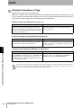
Precautions for Correct Use
1. Installation Environment
Do not install the product in the following locations
• Where it is exposed to direct sunlight
• Where it is exposed to corrosive gases, dust, metal chips, or salt
• Where the operating temperature exceeds the range given in the specifications
• Where there are sudden changes in temperature (including locations subject to condensation)
• Where the humidity exceeds the range given in the specifications
• Where vibration or shock exceeding the values given in the specifications is imposed directly on the product.
• Where the product is subject to splashing water, oil, or chemicals
Precautions for Correct Use
Please observe the following precautions to prevent failure to operate, malfunctions, or undesirable effects on product performance.
2. ID Tag Installation
• This device uses the frequency band 13.56 MHz to communicate with Tags. This frequency band is also used as the
ISM band (one of frequencies assigned to medical or industrial heaters). These heaters may affect communications
with a Tag or may damage the Tag if the heater is located near this device. Do not install ID Tags near devices that
use the frequency band 13.56 MHz.
3. Power Supply
• Use the power supply specified in this manual.
p.68
4. Installation
• Always turn OFF the power supply to the Handy Terminal before inserting or removing the CF Reader/Writer.
• To protect the system from damage due to static electricity, use a wrist strap or other means of preventing static discharge when touching signal wires for terminals or connectors.
• Insert securely into the CF Port.
5. Cleaning
• Do not use any thinner. Resin material and case paint are dissolved by thinner.
6. Communications
• Power is supplied when opening the COM port on the CF Reader/Writer. Wait for at least 500 ms after opening the
COM port before starting communications.
Electromagnetic Inductive RFID System
User's Manual
5
Introduction
Introduction
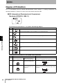
About this Manual
About this Manual
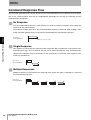
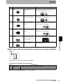
Meaning of Visual Guides
Indicates precautions to be observed in operating the product, advice on operating methods, and important information for maintaining product performance.
Indicates the page numbers where related information can be found.
Indicates information related to troubleshooting.
6
Electromagnetic Inductive RFID System
User's Manual
Introduction
Introduction
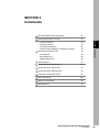
CONTENTS
2
Standard Conformity
4
About this Manual
6
SECTION 1 Product Outline
9
Features
10
Part Names and Functions
11
System Configuration
12
Application Flowchart
13
SECTION 2 Communications Preparations
15
Connection
16
Tags
17
Protective Covers
21
Setting Handy Terminal Communications Conditions
25
Communications Test
26
SECTION 3 Functions
Contents
Introduction
29
Communications Designation Function
30
Setting Operating Parameters
31
Memory Check Function
32
Write Protection
33
Electromagnetic Inductive RFID System
User's Manual
7
Introduction
Introduction
SECTION 4 Commands
Contents
CF Reader/Writer Operation Status
36
Command Response Format
37
Command Response Flow
40
Command List
41
Communications Designations
43
Communications Commands
44
Communications Subcommand
52
Controller Control Commands
53
Host Commands
55
Appraisal Commands
56
End Code List
59
SECTION 5 Troubleshooting
61
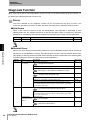
Diagnosis Function
62
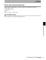
Errors and Countermeasures
63
SECTION 6 Appendices
67
Specifications and Dimensions
68
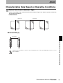
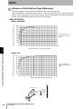
Characteristics Data Based on Operating Conditions
79
Memory Map
83
Maintenance and Inspection
84
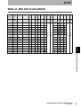
Table of JIS8 Unit Code (ASCII)
85
Degree of Protection
86
Manual Revision History
8
35
Electromagnetic Inductive RFID System
User's Manual
90
SECTION 1
SECTION 1
Product Outline
10
Part Names and Functions
11
System Configuration
12
Application Flowchart
13
Electromagnetic Inductive RFID System
User's Manual
Product Outline
Features
9
SECTION 1
Product Outline
Features
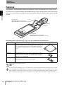
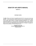
The V670-CF01 CF Reader/Writer combines the V670-series Antenna and Controller into a single unit with a
SECTION 1
CF interface. It has superior portability and operability because it can be used by slotting it into a CF card slot
(Type II) on a Handy Terminal. Tag data can be read and written using serial communications from the Handy
Terminal.
Features
Protective Cover
V670-A75SH155S (For Sharp model)
V670-A75SY8046 (For Symbol Technology model)
CF Reader/Writer
V670-CF01
Handy Terminal
RZ-N155S (Manufactured by Sharp)
PDT8046 (Manufactured by Symbol Technology)
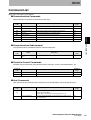
The following three types of ID Tags (“Tags”) can be used with the CF Reader/Writer.
Model
Description
V670-D13F03
The V670-D13F03 ID Tag has a memory capacity of 128 bytes. It is a 40 ×
40 mm square tag with water-resistant properties. It also uses a highly efficient, non-volatile ferroelectric memory, called FeRAM, as internal memory. FeRAM has a semipermanent life (i.e., it can be accessed 1 billion
times).
V670-D13F01
The V670-D13F01 ID Tag is an 8 × 16 mm rectangular tag. It is highly
chemical resistant because a PPS case and highly chemical-resistant
epoxy resin is used on the exterior. It has the same memory capacity and
performance as the V670-D13F03.
V670-D13F01H
The V670-D13F01H ID Tag has the same performance and construction
as the V670-D13F01. It has holes for easy mounting.
Refer to Tags for detailed Tag specifications.
p.70
Ferroelectric memory (FeRAM) is a type of non-volatile memory that can write data much faster than previous types of memory,
such as EEPROM and flash ROM, and it has a semipermanent writing life. Furthermore, the previous types of memory could no
longer hold data if nothing had been written to the memory for a certain period (approximately 10 years). FeRAM, on the other
hand, is far better for data storage because it can hold data as long as data is read or written within a specific period of time.
10
Electromagnetic Inductive RFID System
User's Manual
SECTION 1
Product Outline
Part Names and Functions
SECTION 1
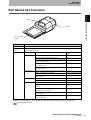
Indicator
Part Names and Functions
Antenna
CF card section
(Type II)
Name
Details
Antenna
The Antenna is brought close to the Tags in order to communicate with them.
CF card section
(Type II)
The interface for connection with a Handy Terminal. Conforms to the CF Card specification: Compact Flash
Specification Revision 2.0.
Indicator
Status
Description
Lit time and number of
flashes
Green, lit
Command received from Handy Terminal
3s
Communications with Tag ended normally
5s
When the result is “A” (low noise level) for the Noise Mea- 5 s
surement command (NS)
When the result is “0” (normal) for the Error Noise Detec- 5 s
tion command (EN)
When the result is “A” (excellent) for the Stability Evalua- 5 s
tion command (SF)
Green, flashing
After completing initialization when power is turned ON
6 times
During communications with a Tag
Until communications end
When the result is “B” (good) for the Stability Evaluation
command (SF)
8 times
Red, lit*
When an error occurs in communications with a Tag
5s
When a CPU error occurs
Until power is turned OFF
Red, flashing
When an error occurs because there is no Tag
10 times
When an error occurs in communications with the Handy
Terminal
5 times
When the result is “B” (high noise level) for the Noise
Measurement command (NS)
15 times
When the result is “1” (error) for the Error Noise Detection 15 times
command (EN)
When the result is “C” (No good) for the Stability Evaluation command (SF)
15 times
* When a CPU error occurs, the indicator will remain lit until the power supply is turned OFF.
p.62 Diagnosis Function
Electromagnetic Inductive RFID System
User's Manual
11
SECTION 1
Product Outline
System Configuration
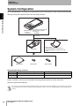
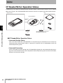
The CF Reader/Writer is inserted into a Handy Terminal CF card slot (Type II) and it controls communications
SECTION 1
with Tags using serial communications from the Handy Terminal.
System Configuration
• Manufactured
by Sharp
RZ-N155S
Recommended Handy Terminals
• Manufactured by Symbol
Technology
PDT8046
CF card slot
Protective Cover
V670-CF01
V670-D13F03
V670-D13F01
• V670-A75SH155S (For Sharp model)
• V670-A75SY8046 (For Symbol Technology
model)
V670-D13F01H
Recommended Handy Terminals
Manufacturer
Symbol Technology*
SHARP
Model
PDT8046
RZ-N155S
OS
PocketPC2002
Windows CE.NET4.2
* The Handy Terminal manufactured by Symbol Technology is recommended for use in the USA, Canada,
Europe, and China. Contact your local Symbol Technology representative for further information.
http://www.symbol.com/index.htm
Use one of the recommended Handy Terminals listed in the above table. The CF Reader/Writer may not operate correctly if any
other Handy Terminal is used. For Handy Terminal operating procedures, refer to the operating instructions provided by the manufacturer.
12
Electromagnetic Inductive RFID System
User's Manual
SECTION 1
Product Outline
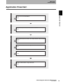
Communications preparation
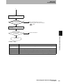
Application Flowchart
Trial operation
SECTION 1
Preparation
Application Flowchart
Connect the CF Reader/Writer.
p.16
Set the Handy Terminal communications conditions.
p.25
Test communications between the Handy Terminal and CF Reader/
Writer.
p.27
Test communications between Tags and the CF Reader/Writer.
p.27
Check the ambient environment.
Communications
p.79
Actual communications using commands.
p.35
Electromagnetic Inductive RFID System
User's Manual
13
SECTION 2
Communications Preparations
SECTION 2
16
Tags
17
Protective Covers
21
Setting Handy Terminal Communications Conditions
25
Communications Test
26
Electromagnetic Inductive RFID System
User's Manual
Communications Preparations
Connection
15
SECTION 2
Communications Preparations
Connection
1. Turn OFF the power supply to the Handy Terminal.
Always turn OFF the power supply to the Handy Terminal before connecting or disconnecting the CF Reader/Writer. For
Handy Terminal operating procedures, refer to the operating instructions provided by the manufacturer.
SECTION 2
Connection
2. Attach the Protective Cover to the end of the Handy Terminal.
Refer to Protective Covers for the attachment method for the Protective Cover.
p.21 Protective Covers
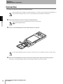
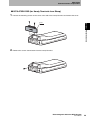
3. Insert the CF Reader/Writer into the Handy Terminal CF card slot.
Insert the CF Reader/Writer into the CF card slot as shown above. Insert it completely to the back of the CF card slot.
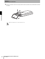
4. After the CF Reader/Writer has been inserted, turn ON the power supply to the Handy Terminal.
The indicator on the CF Reader/Writer will flash after the Handy Terminal power has been turned ON.
16
Electromagnetic Inductive RFID System
User's Manual
SECTION 2
Communications Preparations
Tags
Installation Environment
Do not use Tags in the following locations.
• Locations with corrosive gases, flammable gases, or dust
temperature fluctuations that may cause condensation
• Inside microwave ovens
Tags
Mounting Method
SECTION 2
• Locations with an ambient temperature not between −10 and 70°C and locations subject to sudden
Observe the following precautions when mounting Tags.
• Do not chip or make holes in Tags.
• Do not apply excessive force to Tags.
• Do not mount Tags side-by-side or close to metallic objects.
* Tags may warp if used in an environment subject to repeated high and low temperatures, but this will
not affect Tag functions.
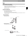
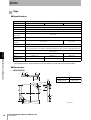
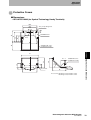
■ V370-D13F01(H)
• Mounting Direction
Mount section
Marking surface
• Mounting Example
Use two M3 screws to mount a Tag.
Mounting Hole Dimensions
Two, M3 holes
20.5±0.1
(Unit: mm)
Electromagnetic Inductive RFID System
User's Manual
17
SECTION 2
Communications Preparations
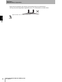
* Tags must be mounted on flat surfaces. Do not mount Tags on curved surfaces.
The Tag may be damaged due to tightening stress if it is mounted on a curved surface.
SECTION 2
Tighten the M3 screws to a torque of 5 N·m or less.
Tags
18
Electromagnetic Inductive RFID System
User's Manual
SECTION 2
Communications Preparations
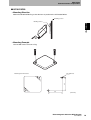
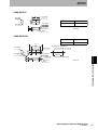
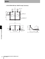
■ V670-D13F03
• Mounting Direction
Mount the V670-D13F03 Tag so that the front is parallel to the CF Reader/Writer.
Mounting section
Marking surface
SECTION 2
Tags
• Mounting Example
Use two M3 screws to mount a Tag.
Mounting Hole Dimensions
32
Two, M3 holes
32
(Unit: mm)
Electromagnetic Inductive RFID System
User's Manual
19
SECTION 2
Communications Preparations
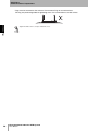
* Tags must be mounted on flat surfaces. Do not mount Tags on curved surfaces.
The Tag may be damaged due to tightening stress if it is mounted on a curved surface.
SECTION 2
Tighten the M3 screws to a torque of 0.6 N·m or less.
Tags
20
Electromagnetic Inductive RFID System
User's Manual
SECTION 2
Communications Preparations
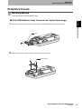
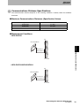
Protective Covers
Mounting Method
Protective Covers are mounted with screws.
SECTION 2
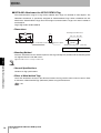
■ V670-A75SY8046 (for Handy Terminals from Symbol Technology)
1. Loosen the screws on the cover at the end of the Handy Terminal and remove the cover.
Protective Covers
Cover
2. Remove the screws from the hand strap bar and remove the bar.
Hand strap bar
Electromagnetic Inductive RFID System
User's Manual
21
SECTION 2
Communications Preparations
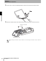
3. Insert the pin as shown in the following diagram to attach the hand strap to the Protective Cover.
Pin
SECTION 2
Protective Covers
4. Secure the Protective Cover to the Handy Terminal with two #4-40 screws and two #2-56 screws.
Mounting screws (#4-40)
Mounting screws (#2-56)
Tighten mounting screws #4-40 to a torque of 0.3 N·m or less, and mounting screws #2-56 to a torque of 0.15 N·m or
less.
22
Electromagnetic Inductive RFID System
User's Manual
SECTION 2
Communications Preparations
■ V670-A75SH155S (for Handy Terminals from Sharp)
1. Loosen the mounting screws on the cover at the end of the Handy Terminal and remove the cover.
SECTION 2
Cover
Protective Covers
2. Remove the screws shown below from the Handy Terminal.
Electromagnetic Inductive RFID System
User's Manual
23
SECTION 2
Communications Preparations
3. Secure the Protective Cover to the Handy Terminal with the four M2 screws provided with the Protective Cover.
SECTION 2
Protective Covers
Tighten the mounting screws to a torque of 0.15 N·m or less.
24
Electromagnetic Inductive RFID System
User's Manual
SECTION 2
Communications Preparations
Setting Handy Terminal Communications Conditions
1. Set the same communications conditions for the Handy Terminal and the CF Reader/Writer.
The default settings for the CF Reader/Writer are as follows: Baud rate: 38,400 bps, Data bits: 8 bits, Parity: even, Stop bits: 1 bit.
Refer to Interface Specifications for details on the communications settings for the CF Reader/Writer.
Setting Handy Terminal Communications Conditions
p.68 Interface Specifications
SECTION 2
For Handy Terminal operating procedures, refer to the operating instructions provided by the manufacturer.
Electromagnetic Inductive RFID System
User's Manual
25
SECTION 2
Communications Preparations
Communications Test
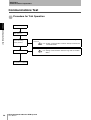
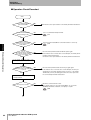
Procedure for Trial Operation
SECTION 2
Turn ON the power.
Communications Test
Visually check operating
status indicator.
Check communications between Handy Terminal and CF Reader/Writer using a Test
Test online using
command.
Handy Terminal.
p.27 Testing Communications between Handy Terminal and
CF Reader/Writer
Checking operation using actual commands.
Trial operation of system.
Trial operation completed.
26
Electromagnetic Inductive RFID System
User's Manual
p.27 Testing Communications between Tags and CF Reader/
Writer
SECTION 2
Communications Preparations
Testing Communications between Handy Terminal and CF
Reader/Writer
A Test command is used to test communications between the CF Reader/Writer and Handy Terminal.
This enables checking the CF card slot connection and communications processing before performing
trial operation of the system.
SECTION 2
1. Send a Test command from the Handy Terminal.
p.55 Test (TS)
2. The CF Reader/Writer will return the received data if the communications network is operating normally.
Refer to Errors and Countermeasures if there is no response from the CF Reader/Writer.
Communications Test
Refer to Test (TS) for information on using the Test command.
p.63 Errors and Countermeasures
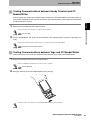
Testing Communications between Tags and CF Reader/Writer
Actual commands are used to test communications between Tags and the CF Reader/Writer.
1. Enter the Read command from the Handy Terminal.
Refer to Commands for information on how to use the command.
p.35 Commands
2. Bring the antenna on the CF Reader/Writer close to the Tag.
Keep the surface of the antenna on the CF Reader/Writer parallel to the Tag surface.
Electromagnetic Inductive RFID System
User's Manual
27
SECTION 2
Communications Preparations
3. When the CF Reader/Writer is within the communications area, the data in the Tag’s internal memory
will be read and displayed on the Handy Terminal.
SECTION 2
Communications Test
28
Electromagnetic Inductive RFID System
User's Manual
SECTION 3
Functions
Setting Operating Parameters
31
Auto Command Abort Time
31
Write Verification
31
Memory Check Function
32
Write Protection
33
Electromagnetic Inductive RFID System
User's Manual
Functions
30
SECTION 3
Communications Designation Function
29
SECTION 3
Functions
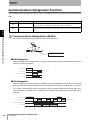
Communications Designation Function
The CF Reader/Writer automatically detects Tags for the communications commands given in the following
table.
Symbol
Name
SA
Description
Single Auto command
After the Single Auto command has been received, a communication is executed when a
Tag is detected in the communications area and a response is returned.
Repeat Auto command
The operation specified under SA is repeatedly executed. The CF Reader/Writer communicates only once with each Tag, even if that Tag continues to be in the communications
area.
RA
SECTION 3
Communications Designations (SA/RA)
Communications Designation Function
SA and RA automatically detect Tags and communicate with them.
CF Reader/Writer
Tag
Communications are started when a
Tag enters the communications area.
■ SA Designation
When the Single Auto command (SA) is specified, command processing is completed when communications have been completed.
Host to CF Reader/Writer
SA command
Response
CF Reader/Writer to Host
- Processing completed -
Communications
Between CF Reader/Writer and Tag
Tag
(Tag movement)
■ RA Designation
When the Repeat Auto command (RA) is specified, the CF Reader/Writer waits for the next Tag each
time communications are completed. Once communications have been performed with a Tag, there
are no more communications with that Tag until the Tag has moved outside the communications area.
This processing is repeated until it is ended when the Command Processing Abort command (AA) is
received.
Host to CF Reader/Writer
CF Reader/Writer to Host
Between CF Reader/Writer and Tag
AA command
RA command
Waiting for a new Tag
Communications A
Tag A
(Tag movement)
30
Electromagnetic Inductive RFID System
User's Manual
Response
Response
Response
Waiting for a Tag
Communications B
Waiting for a new Tag
Communications C
Tag B
Tag C
Response
- Processing completed -
SECTION 3
Functions
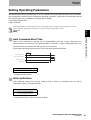
Setting Operating Parameters
The operating parameters outlined below can be set to optimize CF Reader/Writer performance and reliability,
and to optimize the system itself. If changing the operating parameters, always do so with the power turned
ON. Normally, there are no problems in using the default settings.
• Auto command abort time
• Write verification
The CF Reader/Writer is initialized when the power is turned OFF and the operating parameter settings are not stored.
Refer to Parameter Setting (SP) for information on using the Parameter Setting (SP) command.
SECTION 3
p.53
When an Auto command is received, the CF Reader/Writer waits until a Tag is detected in the
communications area and then starts communications. If, however, a Tag is not detected within a set
period, processing is aborted and a No Tag error (72) is returned.
A command error will be returned if "00" is set as the Abort auto command time.
CF Reader/Writer to Tag
Transmission
Tag to CF Reader/Writer CF
Setting Operating Parameters
Auto Command Abort Time
Response
Reader/Writer to Host
Error 72
Auto command abort time
External input
Setting range
01 to 60 s
* The default setting is 10 s.
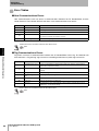
Write Verification
Write verification checks that any data written to Tags is correct. A verification error (71) will be
returned if the data is not written correctly.
Setting range
0 (write verification disabled)
1 (write verification enabled)
* The default setting is 1 (write verification enabled).
Electromagnetic Inductive RFID System
User's Manual
31
SECTION 3
Functions
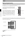
Memory Check Function
A check code can be added to the data in a Tag to detect errors from memory write life or unexpected causes.
The polynomial X16 + X12 + X5 + 1 is used to generate a CRC code as the check code.
Use the Memory Check command (MD) to write and verify commands.
Address
In the check block, which is specified using the start
00
address and the number of bytes, all but the last two bytes
01
are the calculation area. The last two bytes of the block are
the check code area.
SECTION 3
Area start address
When a Check Code Write command is sent, the CRC
Check code calculation area
(check block bytes − 2)
code for the data in the calculation area is calculated and
Memory Check Function
written to the check code area. When a Data Verify
command is sent, the CRC code for the data in the
calculation area is calculated and compared to the data in
CRC (leftmost)
the check code area. When the data matches, “0” is
CRC (rightmost)
Check code area (2 bytes)
returned as the response status flag to indicate that the
data is normal. If the data does not match, “1” is returned
as a warning.
Calculate and write the check code using the Memory Check command (MD) after writing data and verify the
check code before reading data. This enables detecting in advance data corruption in Tags that can occur
while the Tags are not being accessed.
Writing stage
Data write
Check code calculation
Reading stage
Check code verification
Data read
Refer to Memory Check (MD) when using the Memory Check function.
p.48
32
Electromagnetic Inductive RFID System
User's Manual
SECTION 3
Functions
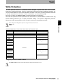
Write Protection
The write protection function is a protective function designed to prevent fixed data, such as palette
information or product information, stored in a Tag memory from being erased by accidental overwriting. Any
area of specified addresses can be write protected (a maximum of two areas) by setting protection information
in the Tag. A protection error will occur if a write is executed for any write-protected page.
Part of the user data area ($0000 to $0003) is used for protection area information.
To enable write protection, write the protection area information to a specified address and then use the Tag
Function Setting command (TF) to specify “Protection Setting” in the process designation parameter.
SECTION 3
Similarly, to disable write protection, specify “Disable” in the process designation parameter.
Refer to Tag Function Designation (TF) when using the write protection function.
p.49
Write Protection
Relationship between Protection Information and Protection Area
User address
Description
Data example
$0000
Start address of write protection area 1
05h
$0001
End address of write protection area 1
10h
$0002
Start address of write protection area 2
70h
$0003
End address of write protection area 2
75h
$0004
$0005
.
.
Write protection area
1
$0010
$0011
.
.
$006F
User area
$0070
.
.
Write protection area
2
$0075
$0076
$007F
* Range for protection area: 0004h to 007Fh
Area $0000 to $0003 cannot be used as data area if the write protection function is used.
Electromagnetic Inductive RFID System
User's Manual
33
SECTION 4
Commands
CF Reader/Writer Operation Status
36
Command Response Format
37
37
Response Frames
37
Data Type Designation
38
39
40
No Response
40
Single Response
40
Multiple Responses
40
Command List
41
Communications Designations
43
Communications Commands
44
Communications Subcommand
52
Controller Control Commands
53
Host Commands
55
Appraisal Commands
56
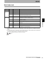
End Code List
59
Electromagnetic Inductive RFID System
User's Manual
Commands
Ranges for Start Address and Number of Bytes
Command Response Flow
SECTION 4
Command Frames
35
SECTION 4
Commands
CF Reader/Writer Operation Status
A command (1) sent from the connected Handy Terminal initiates communication between the CF Reader/
Writer and a Tag (2). The CF Reader/Writer then returns the result as a response (3) to the Handy Terminal.
Handy Terminal
Tag
CF Reader/Writer
Communications
SECTION 4
(1)
CF Reader/Writer Operation Status
Command
(2)
Communications between the CF
Reader/Writer and the Tag
(3)
Response
■ CF Reader/Writer Operation Status
• Command Standby Status
This is the status where the CF Reader/Writer is not processing any commands, but can accept any
command except subcommands. When a command is received, the CF Reader/Writer enters the
command processing status.
• Command Processing
Once a command has been received, the CF Reader/Writer ignores the next command until processing of the received command has been completed. Command processing abort and reset commands,
however, can always be received.
36
Electromagnetic Inductive RFID System
User's Manual
SECTION 4
Commands
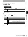
Command Response Format
Command Frames
Data
Command code
Terminator
*
2
n
CR
2
Name
Description
Command code
Specifies the command.
Data
Specifies the parameters for command execution (address, number of bytes, etc.) or specifies the data to
be written.
Terminator
Indicates the end of a command, using the two characters “*” ($2A) and the carriage return code ($0D).
SECTION 4
Response Frames
End code
Status
Retry flag flag
Data
Terminator
*
2
2
1
1
n
Command Response Format
Command code
CR
2
Name
Description
Command code
The same data as the sent command frame is added and returned.
End code
Shows the command execution result.
Retry flag
Always 0.
Status flag
A code that shows the status of command execution.
0
Normal
Indicates that the processing was completed normally.
1
Tag data status
Indicates that the verification result of the Memory Check command (MD)
detected an error, or that an overflow/underflow occurred in the calculation of a
Computation Write command (CW).
2
Abort status
Indicates a communication with a Tag was aborted after it was started, using
the aborting command (AA).
Data
Provides the data read according to the command.
Terminator
Indicates the end of a command, using the two characters “*” ($2A) and the carriage return code ($0D).
Electromagnetic Inductive RFID System
User's Manual
37
SECTION 4
Commands
Data Type Designation
The data type to be used when transmitting read or write data between the CF Reader/Writer and the
Handy Terminal can be specified in a command. Either ASCII or hexadecimal can be used.
■ ASCII (JIS8 Unit Code) Designation “A”
One byte of data in a Tag is transmitted directly as ASCII or JIS8 unit code. Each transmitted character
is equivalent to 1 byte of data in the Tag. Character data can be directly read or written, but do not use
the carriage return (CR) control code in send data. If the CR control code is used in write data, a command error will occur.
• Data Write Example
If “V670” is specified as the write data for 4 bytes of memory beginning with the address 10h, the data is written to the Tag memory
SECTION 4
as shown in the diagram.
Command
W
T
Command Response Format
Command
S
A
Communications designation
A
1
0
ASCII Antenna
desig- designanation
tion
0
1
0
Start address
0
4
V
6
No. of bytes
7
*
0
CR
Write data
• Data Read Example
Tag memory
If 4 bytes of memory is read starting with address 10h, the read
Address
10h
5
6
"V"
11h
3
6
"6"
12h
3
7
"7"
13h
3
0
"0"
data will be “V670” for the data shown in the diagram.
Response
R
D
Command
0
0
End code
0
Retry
flag
0
V
6
Status
flag
7
*
0
CR
Read data
■ Hexadecimal (JIS8 Unit Code) Designation “H”
One byte of Tag data is converted to two hexadecimal characters (00 to FF) and transmitted. Each
transmitted character is equivalent to 1 byte of data in the Tag. Always set write data in the 2-character
units 00 to FF (i.e., as an even number of characters). A command error will occur if an odd number of
characters is accidentally set.
• Data Write Example
If “56363730” is specified as the write data for 4 bytes of memory beginning with the address 10h, the
data is written to the Tag memory as shown in the diagram.
Command
W
T
Command
S
A
H
1
0
Communica- HEX Antenna
tions desig- desig- designanation
tion
nation
0
1
0
Start address
0
4
5
6
3
No. of bytes
6
3
7
3
*
0
CR
Write data
• Data Read Example
Tag memory
If you read 4 bytes of memory starting with address 10h, the read data
Address
10h
5
6
11h
3
6
12h
3
7
13h
3
0
will be "56363730" for the data shown in the diagram.
Response
R
D
Command
38
0
0
End code
0
0
5
6
Retry Status
flag
flag
Electromagnetic Inductive RFID System
User's Manual
3
6
Read data
3
7
3
0
*
CR
SECTION 4
Commands
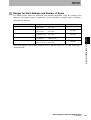
Ranges for Start Address and Number of Bytes
The following table shows the commands and available designation range for specifying start
addresses and number of bytes in commands. If a value outside the available range is specified, a
command error will occur.
Command code
Ranges for start address and number of bytes
Other restrictions
A) Start address:
B) No. of bytes:
0000h to 007Fh
01h to 80h
A+B ≤ 80h*
Write (WT)
A) Start address:
B) No. of bytes:
0000h to 007Fh
01h to 80h
A+B ≤ 80h*
Computation Write (CW)
A) Start address:
B) Calculation area:
0000h to 007Fh
01h to 04h
A+B ≤ 80h*
Data Fill (DF)
A) Start address:
B) End address:
0000h to 007Fh
0000h to 007Fh
A≤B
Memory Check (MD)
A) Start address:
B) No. of check bytes:
0000h to 007Dh
03h to 80h
A+B ≤ 80h*
command error.
Electromagnetic Inductive RFID System
User's Manual
Command Response Format
* If the start address is 20h and the number of bytes is 70h, the result is A + B = 90h, which gives a
SECTION 4
Read (RD)
39
SECTION 4
Commands
Command Response Flow
The command received from the Handy Terminal by the CF Reader/Writer may be different to the response
sent to the Handy Terminal from the CF Reader/Writer, depending on the type of command and the
communications designation.
No Response
If the CF Reader/Writer receives a reset command, it sends no response, performs reset processing,
and waits for the next command.
The indicator will light green when the CF Reader/Writer receives a command. After sending a command, check the indicator to be sure that the CF Reader/Write has received the command.
SECTION 4
Host device
CF Reader/Writer
Reset command
Executes reset processing
Command Response Flow
Single Response
One response is returned for one command when single auto (SA) is specified in a command for communicating with Tags, when commands that are not for communicating with Tags (communications
subcommand, controller control commands, or host commands) are specified, when appraisal commands are specified, etc.
Host device
CF Reader/Writer
Command
Response
Multiple Responses
Multiple responses are returned for one command when repeat auto (RA) is specified in a command
for communicating with Tags.
Host device
CF Reader/Writer
Command
Response
40
Electromagnetic Inductive RFID System
User's Manual
Response
Response
Response
SECTION 4
Commands
Command List
There are 5 main types of commands.
■ Communications Commands
Communications commands to communicate with Tags.
Command
code
RD
Name
Read
Description
Reference
page
Reads Tag memory data.
p.44
WT
Write
Writes data to Tag memory.
p.45
CW
Computation Write
Writes memory data and the calculation result to Tags.
p.46
DF
Data Fill
Writes designated data to a designated area.
p.47
Memory Check
Sets and verifies Tag memory check codes.
p.48
TF
Tag Function Designation
Sets/clears the write protection for Tags.
p.49
ID
ID Read
Reads the Tag user ID.
p.51
The communications subcommand aborts command execution.
Command
code
AA
Name
Command Processing
Abort
Description
Aborts communications with a Tag.
Reference
page
Command List
■ Communications Subcommand
SECTION 4
MD
p.52
■ Controller Control Commands
Controller control commands stop communications with Tags, reset the CF Reader/Writer., etc.
Command
code
Name
Description
Reference
page
SP
Parameter Setting
Sets all CF Reader/Writer parameters.
p.53
XZ
Reset
Resets the CF Reader/Writer.
p.54
■ Host Commands
Host commands test communications between the CF Reader/Writer and the Handy Terminal.
Command
code
Name
Reference
page
Test
Checks the status of communications between the Handy Terminal
and the CF Reader/Writer.
Returns data received from the Handy Terminal to as is.
p.55
Version Information
Reads the CF Reader/Writer model information, software version,
and creation date.
p.55
TS
VS
Description
Electromagnetic Inductive RFID System
User's Manual
41
SECTION 4
Commands
■ Appraisal Commands
Appraisal commands investigate the occurrence of ambient noise and evaluate communications stability.
Command
code
Name
Description
Detects noise level.
NS
Noise Measurement
EN
Error Noise Detection
Detects noise above a certain level.
p.57
SF
Stability Evaluation
Reads data from the Tag and evaluates the received data.
p.58
SECTION 4
Command List
42
Electromagnetic Inductive RFID System
User's Manual
Reference
page
p.56
SECTION 4
Commands
Communications Designations
The following two communications designations can be specified using communications commands.
Communications designation code
SA
RA
Name
Description
Single auto
After the Single Auto command has been received, a communication is executed when a Tag is
detected in the communications area and a response is returned.
Repeat auto
The operation specified under SA is repeatedly executed. The CF Reader/Writer
communicates only once with each Tag, even if that Tag continues to be in the communications
area. Processing can be canceled by the Command Processing Abort command and the
Parameter Setting command (auto command abort time).
SECTION 4
Communications Designations
Electromagnetic Inductive RFID System
User's Manual
43
SECTION 4
Commands
Communications Commands
This section describes the commands used for communicating with Tags.
Read (RD)
Reads data from the area specified by start address and number of bytes.
Command
Command
code "RD"
Communications designation
2
2
Data Antenna
desig- designanation
tion
1
Communications
designation
Read area start
address
No. of read
bytes
4
2
1
*
CR
2
Specifies the method for communicating with a Tag.
Refer to Communications Designations for details.
SECTION 4
p.43
Communications Commands
Data designation
Specifies the data format when sending the read data response.
“A”: ASCII
“H”: Hexadecimal
Antenna designation
Always “1”.
Read area start address
Specifies the start address in the Tag memory area for reading data in four hexadecimal digits.
Specification range: 0000h to 007Fh
No. of read bytes
Specifies the number of bytes of data to be read from the Tag in two hexadecimal digits.
The maximum number of characters that can be read at one time is 256.
Specification range: 01h to 80h
Response
Command
code "RD"
End code
"00"
2
2
Read data
Retry Status
flag
flag
1
1
Read data
*
Specified number of bytes
CR
2
Data read from the Tag.
The number of characters is the number of read bytes in ASCII, and the
number of read bytes times 2 in hexadecimal.
Example: Reading 8 Bytes of Data Starting from Address 0000h (Single Auto, Hexadecimal)
Send data:
RDSAH1000008*[CR]
Receive data: RD00001234567812345678*[CR]
Specify the total number of read bytes so that the sum of the read area start address and the number of bytes does not
exceed the Tag memory capacity (128 bytes).
Example: The number of bytes can be specified between 01h and 70h for a start address of 0010h.
44
Electromagnetic Inductive RFID System
User's Manual
SECTION 4
Commands
Write (WT)
Writes the specified number of bytes of data starting from the specified start address to a Tag.
Command
Command
code "WT"
Write area start
address
Communica- Data Antenna
tions designa- desig- designanation
tion
tion
2
2
1
Communications
designation
1
No. of write
bytes
Write data
2
Specified number of bytes
4
*
CR
2
Specifies the method for communicating with a Tag.
Refer to Communications Designations for details.
p.43
Antenna designation
Always “1”.
Write area start address
Specifies the start address in the Tag memory area for writing data in four hexadecimal digits.
Specification range: 0000h to 007Fh
No. of write bytes
Specifies the number of bytes of data to be written to the Tag in two hexadecimal digits.
Specification range: 01h to 80h
Write data
Data written to Tags.
There will be 2 characters per byte if hexadecimal is specified.
Response
Command
code "WT"
End code
"00"
2
2
Retry Status
flag
flag
1
*
1
CR
2
Communications Commands
Specifies the data format when sending write data to Tags.
“A”: ASCII
“H”: Hexadecimal
SECTION 4
Data designation
Example: Writing 4 Bytes of Data (“11223344”) from Address 0010h (Single Auto, Hexadecimal)
Send data:
WTSAH100100411223344*[CR]
Receive data: WT0000*[CR]
Specify the total number of write bytes so that the sum of the write area start address and the number of bytes does not
exceed the Tag memory capacity (128 bytes).
Example: The number of bytes can be specified between 01h and 70h for a start address of 0010h.
Electromagnetic Inductive RFID System
User's Manual
45
SECTION 4
Commands
Computation Write (CW)
Performs a hexadecimal calculation using the data in Tag memory and the calculation data and writes
the result to the Tag. If an overflow occurs for addition or an underflow occurs for subtraction, the data
is not written to the Tag and “1” is returned for the status flag.
Command
Command
code "CW"
Communications designation
2
2
Proc- Antenna
ess designadesig- tion
nation
1
Communications
designation
Calculation area
start address
1
No. of bytes
in calculation
area
4
Calculation data
*
Specified number of bytes
2
CR
2
Specifies the method for communicating with a Tag.
Refer to Communications Designations for details.
p.43
SECTION 4
Communications Commands
Process designation
Specifies the calculation method.
“A”: Hexadecimal addition
“S”: Hexadecimal subtraction
Antenna designation
Always “1”.
Calculation area start
address
Specifies the start address in the Tag memory area for calculating data in four hexadecimal digits.
Specification range: 0000h to 007Fh
No. of bytes in calculation
area
Specifies the number of bytes of calculation data in the calculation area in two hexadecimal digits.
Specification range: 01h to 04h
Calculation data
Specifies in hexadecimal the number to be used in the calculation.
Response
Command
code "CW"
End code
"00"
2
2
Results data
Retry Status
flag
flag
1
1
Results data
*
Specified number of bytes
CR
2
Returns the calculation results data written to the Tag.
The data before the calculation was performed will be returned if addition gives an overflow or
subtraction gives an underflow. The status flag will be “1” in these cases.
Example: Writing 2 Bytes of Data, the Result of Subtracting the Subtraction Data “0002” from “0010”,
the Data Starting at Address 0001h (Single Auto, Initial Value: “0010”)
Send data:
CWSAS10001020002*[CR]
Receive data: CW0000000E*[CR]
This command performs hexadecimal calculations, so specify hexadecimal for all data being handled. Also, set the calculation area so that it is contained within one page. If the calculation area is not contained within one page, a command error will occur.
p.83 Memory Map
46
Electromagnetic Inductive RFID System
User's Manual
SECTION 4
Commands
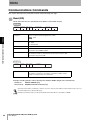
Data Fill (DF)
Writes one or two bytes of the same data to a specified Tag area. The write data is specified in hexadecimal.
Command
Command
code "DF"
Communications designation
2
2
Write area
start address
Data Antenna
desig- designanation
tion
1
Communications
designation
1
4
Write area
end address
Write data
4
1 or 2 bytes
worth of data
*
CR
2
Specifies the method for communicating with a Tag.
Refer to Communications Designations for details.
p.43
Specifies the size of the write data.
“B”: Bytes
“W”: Words (2 bytes)
Antenna designation
Always “1”.
Write area start address
The address in the Tag for writing data is specified in four hexadecimal digits.
Specification range: 0000h to 007Fh
Write area end address
The end address in the Tag for writing data is specified in four hexadecimal digits.
Specification range: 0000h to 007Fh
Write data
Data written to Tags.
Set one byte of hexadecimal if “B” is specified under Data designation, two bytes if “W” is
specified.
SECTION 4
Data designation
Command
code "DF"
End code
"00"
2
2
Retry Status
flag
flag
1
*
1
CR
Communications Commands
Response
2
Example: Writing Fill Data “00FF” from Address 0000h to 007Fh (Single Auto, Writing 2 Bytes)
Send data:
DFSAW10000007F00FF*[CR]
Receive data: DF0000*[CR]
The volume of data communications with the Handy Terminal can be reduced by writing fill data to a specified area, so
the use of this command can improve the efficiency of the system.
Electromagnetic Inductive RFID System
User's Manual
47
SECTION 4
Commands
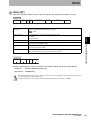
Memory Check (MD)
Calculates the check code for the specified block using the polynomial X16 + X12 + X5 + 1, and verifies
the result against the check code attached to the check block.
Command
Command
code "MD"
Communications designation
2
2
Proc- Antenna
ess
designadesigtion
nation
1
Communications
designation
Check block start
address
No. of check
block bytes
4
2
1
*
CR
2
Specifies the method for communicating with a Tag.
Refer to Communications Designations for details.
p.43
SECTION 4
Process designation
Specifies the check process.
“K”: Check code calculation
“C”: Check code verification
Antenna designation
Always “1”.
Communications Commands
Check block start address Specifies the check block start address in four hexadecimal digits.
Specification range: 0000h to 007Dh
No. of check block bytes
Specifies the number of check block bytes in two hexadecimal digits.
Specification range: 03h to 80h
Response
Command
code "MD"
End code
"00"
2
2
Status flag
Retry Status
flag
flag
1
*
1
CR
2
Shows the check code verification result.
“0”: Verification normal
“1”: Verification error
Example: Adding a Check Code to 4 Bytes of Data from Address 0010h (Single Auto)
Send data:
MDSAK1001006*[CR]
Receive data: MD0000*[CR]
* The specified number of bytes will be 6, with 2 bytes of check code attached to 4 bytes of data.
Do not write required data in the last two bytes of the area. These two bytes are used to record the check code.
Refer to Memory Check Function for details.
p.32
48
Electromagnetic Inductive RFID System
User's Manual
SECTION 4
Commands
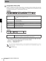
Tag Function Designation (TF)
Sets/clears write protection for Tags.
Command
Command
code "TF"
Communica- Proc- Antenna
desigess
tions desigdesig- nation
nation
nation
2
2
1
Communications
designation
*
CR
2
1
Specifies the method for communicating with a Tag.
Refer to Communications Designations for details.
p.43
Specifies setting or clearing the function.
“P”: Sets protection.
“R”: Clears protection.
Antenna designation
Always “1”.
SECTION 4
Process designation
Communications Commands
Response
Command
code "TF"
End code
2
2
Retry Status
flag
flag
1
1
*
CR
2
■ Setting Example
Relationship between Protection Information and Protection Area
User address
Description
Data example
$0000
Start address of write protection area 1
05h
$0001
End address of write protection area 1
10h
$0002
Start address of write protection area 2
70h
$0003
End address of write protection area 2
75h
$0004
$0005
.
.
Write protection area
1
$0010
$0011
.
.
$006F
User area
$0070
.
.
Write protection area
2
$0075
$0076
$007F
* Protection area setting range: 0004h to 007Fh
Electromagnetic Inductive RFID System
User's Manual
49
SECTION 4
Commands
• No Write Protection
When write protection is not set for the Tag:
Send data:
TFSAR1*[CR]
Receive data: TF0000*[CR]
• Write Protection Specified for One Location
When setting write protection for Tag memory addresses 0005h to 0010h
(single auto, hexadecimal)
Setting Protection Area Information
Send data:
WTSAH100000405100510*[CR]
Receive data: WT0000*[CR]
SECTION 4
Setting Write Protection
Send data:
TFSAP1*[CR]
Receive data: TF0000*[CR]
Communications Commands
When setting write protection for only one location, set the same data to addresses 0002h and 0003h and to addresses
0000h and 0001h.
• Write Protection Specified for Two Locations
When setting write protection for Tag memory addresses 0005h to 0010h and addresses 0070h to
0075h (single auto, hexadecimal)
Setting Protection Area Information
Send data:
WTSAH100000405107075*[CR]
Receive data:
WT0000*[CR]
Setting Write Protection
Send data:
TFSAP1*[CR]
Receive data:
TF0000*[CR]
Refer to Write Protection for details on write protection.
p.33
50
Electromagnetic Inductive RFID System
User's Manual
SECTION 4
Commands
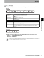
ID Read (ID)
Reads the Tag’s user ID.
Command
Command
code "ID"
Communica- Data Antenna
tions desig- desig- designanation
nation
tion
2
2
1
Communications
designation
*
CR
2
1
Specifies the method for communicating with a Tag.
Refer to Communications Designations for details.
p.43
Always “H” (hexadecimal).
Antenna designation
Always “1”.
SECTION 4
Data designation
Response
End code
"00"
2
2
Read data
Retry Status
flag
flag
1
1
Communications Commands
Command
code "RD"
Read data
*
Specified number of bytes
CR
2
User ID data read from a Tag.
00000000 to 3FFFFFFF
The leftmost 2 bits are system bits and are always 0.
Example: Reading Tag User ID (Single Auto, User ID: “12345678”)
Send data:
IDSAH1*[CR]
Receive data: ID000012345678*[CR]
All Tags store their own unique ID. The ID Read command can be used for very fast communications if all that is
required is to detect whether or not there is a Tag in the communications area.
Electromagnetic Inductive RFID System
User's Manual
51
SECTION 4
Commands
Communications Subcommand
The communications subcommand is used in combination with communications commands. No
communications processing is performed with Tags when the communications subcommand is used alone.
Command Processing Abort (AA)
Aborts processing of a command being executed and returns to the command standby status. Command Processing Abort can be executed during the processing of any command.
Command
Command
code "AA"
Proc- Antenna
desigess
desig- nation
nation
2
SECTION 4
Communications Subcommand
52
1
*
CR
2
1
Process designation
Always “0”.
Antenna designation
Always “1”.
Response
Command
code "AA"
End code
2
2
Retry
flag
Status
flag
1
1
*
CR
2
When command processing has been aborted after a Tag is detected, the status flag will be “2”.
Example: Aborting Command Processing during Execution
Send data:
AA01*[CR]
Receive data: AA0000*[CR]
Electromagnetic Inductive RFID System
User's Manual
SECTION 4
Commands
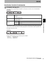
Controller Control Commands
Parameter Setting (SP)
This command sets communications conditions by setting the parameters in the CF Reader/Writer.
Command
Command
code "SP"
Process
code
Parameter data
(only when
changing)
(Upper) (Lower)
2
*
CR
2
2
Process code (upper digit) Specifies the process to be performed for the parameter.
“0”: Change
“1”: Read
“9”: Initialize (default setting)
Parameter*
Setting range
4
Set two decimal digits 01 to 60 (unit: 1 s). A command error will occur if 00 is set.
Default: 10 s.
C
0: OFF, 1: ON, Default: 1 (Write verification enabled)
* The parameter number for the parameter data is the number specified in the lower digit of the process
code. Set the parameter data within the setting range given for the parameter number specified in the
lower digit of the process code.
Response
Command
code "SP"
End code
2
2
Retry Status
flag
flag
1
Parameter data
(only when
reading)
1
*
CR
Controller Control Commands
Parameter data
(only when changing the
parameter)
SECTION 4
Process code (lower digit) Specifies the parameter.
“4”: Auto command abort time
“C”: Write verification
2
Example: Setting Character Interval Monitoring Time to 500 ms
Send data:
SP010500*[CR]
Receive data: SP0000*[CR]
Electromagnetic Inductive RFID System
User's Manual
53
SECTION 4
Commands
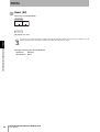
Reset (XZ)
Resets the CF Reader/Writer.
Command
Command
code "XZ"
*
CR
2
2
Response
No response is sent.
A response is not returned for the Reset (XZ) command. The indicator will flash green when this command is received.
SECTION 4
Check the indicator after sending this command to confirm that it has been received.
Controller Control Commands
54
Example: Resetting the CF Reader/Writer
Send data:
XZ*[CR]
Receive data: None
Electromagnetic Inductive RFID System
User's Manual
SECTION 4
Commands
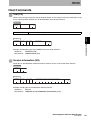
Host Commands
Test (TS)
Returns the message sent by the Handy Terminal directly as the response. The Test command is used
to test communications between the CF Reader/Writer and a Handy Terminal.
Command
Command
code "TS"
Message data
*
CR
2
2
Message data
Any character string for testing communications.
SECTION 4
Response
End code
2
2
Retry Status
flag
flag
1
Message data
*
CR
Host Commands
Command
code "TS"
2
1
Example: Sending Message Data “OMRON” from the Handy Terminal
Send data:
TSOMRON*[CR]
Receive data: TS0000OMRON*[CR]
Version Information (VS)
Reads the CF Reader/Writer model information, software version, and creation date and time.
Command
Command
code "VS"
*
CR
2
2
Response
Command
code "VS"
End code
2
2
Retry Status
flag
flag
1
Model information; software version; creation date and time
*
CR
2
1
Example: Reading the CF Reader/Writer Software Version
Send data:
VS*[CR]
Receive data: VS0000V670-CF01$00000000;1.00;2004/04/01*[CR]
Electromagnetic Inductive RFID System
User's Manual
55
SECTION 4
Commands
Appraisal Commands
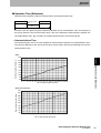
If errors are frequent during communications with Tags, one of the causes may be ambient noise. The
appraisal commands are used to investigate whether or not noise is the cause of errors. It can also be used to
check noise generation at installation sites before installing V670-series Tags or Antennas and Controllers.
Even if read results are normal, reception waveforms may exhibit interference. These commands can be used
to check for noise at the waveform level to provide more detailed information on the actual status of the
waveforms.
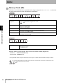
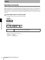
Noise Measurement Command (NS)
Investigates the noise level when commands are received.
SECTION 4
Command
Command
code "NS"
*
CR
2
2
Appraisal Commands
Response
Command
code "NS"
End code
2
2
Retry Status
flag
flag
1
Noise evaluation result
1
Result of
noise level
measurement
1
*
CR
2
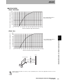
The noise level is evaluated as the maximum absolute value in the measured data.
“A”: Low noise level (0.0 V to 2.0 V); indicator will light green.
“B”: High noise level (2.0 V to 3.3 V); indicator will flash red.
Example: Investigating Ambient Noise Level
Send data:
NS*[CR]
Receive data: NS00000A*[CR]
56
Electromagnetic Inductive RFID System
User's Manual
SECTION 4
Commands
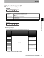
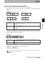
Error Noise Detection Command (EN)
The Error Noise Detection command detects noise above a specified level.
When deciding where to mount Tags and Antennas, use this command to investigate where the noise
level is high.
Command
Specifying Data 1 and Data 2
Command
code "EN"
Data
1
2
2
Data
2
*
Command
code "EN"
CR
2
4
2
Omitting Data 2
Data
1
2
2
*
Data
2
*
CR
2
4
Omitting Data 1 and Data 2
Command
code "EN"
CR
2
2
*
CR
SECTION 4
Command
code "EN"
Omitting Data 1
2
Specifies the error noise level in two decimal digits. (This setting may be omitted*).
Specification range: 00 to 33 (× 0.1 V)
Default: 2.0 V
When “00” is specified: 100%
Data 2
Measurement time
Specifies the error noise measurement time in four decimal digits. (This setting may be omitted*).
Specification range: 0000 to 0100 s
Default: 0060 s
When “0000” is specified: Noise level when command is received is returned in the response.
Appraisal Commands
Data 1
Error noise level
* When both data 1 and data 2 are omitted, noise detection is performed using the previously specified
values. If they are omitted the first time this command is set after turning ON the power supply, the
default settings will be used for noise detection.
Response
Command
code "EN"
End code
2
2
Retry Status Judgeflag
flag
ment
result
1
1
Maximum
noise level
1
2
*
CR
2
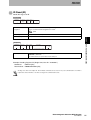
Judgment result
The noise level is evaluated as the maximum absolute value in the measured data.
“0”: Normal; indicator will light green.
“1”: Error; indicator will flash red.
Maximum noise level
Gives the maximum noise level (V) detected during the measurement period in two decimal digits.
Unit: 0.1 V
Example: Detecting Noise at 3.3 V or Greater during a Period of 5 s
Send data:
EN330005*[CR]
Receive data: EN0000020*[CR]
The Error Noise Detection command can be canceled using the Command Processing Abort command (AA), because
no response is given for a set period of time.
p.52
Electromagnetic Inductive RFID System
User's Manual
57
SECTION 4
Commands
Stability Evaluation Command (SF)
The Stability Evaluation command evaluates the stability of received data.
Data is read from the Tag, the received data is evaluated, and the evaluation results are returned in the
response and through the indicator. Forty bytes of data is read starting from address 0000h.
Evaluation Criteria
Response
Meaning
A
Evaluation criteria
Excellent Min. 80% within distribution range
B
Good
C
Min. 60% within distribution range
No good Less than 60% within distribution range
Command
SECTION 4
Appraisal Commands
58
Command
code "SF"
*
2
CR
2
Response
Command
code "SF"
End code
2
2
Retry Status Judgeflag
flag
ment
result
1
1
*
1
CR
2
Example: Investigating Communications Stability
Send data:
SF*[CR]
Receive data: SF0000A*[CR]
Electromagnetic Inductive RFID System
User's Manual
Indicator
Lit green.
Flashing green.
Flashing red.
SECTION 4
Commands
End Code List
Type
End code
Name
Description
Normal end
Host
communications
error*1
10
Parity error
A parity error has occurred in the characters in the command.
11
Framing error
A framing error has occurred in the characters in the command.
12
Overrun error
An overrun error has occurred in the characters in the command.
14
Format error
The command format is incorrect.
The character interval exceeds the set time.
18
Frame length error
A command string longer than 300 characters was received.
70
Communications error
An error occurred during communications with a Tag, and the
communications could not be completed normally.
71
Verification error
The correct data could not be written to the Tag (only possible when
verification is enabled).
72
No-tag error
There is no Tag in the CF Reader/Writer communications area.
7A
Address designation
error
The designated processing address is not suitable, and the execution is
impossible.
7D
Write protection error
Data was written to a write-protected page.
7E*2
Lock error
Write was specified for a locked area.
7F*2
Tag error
Communications were attempted with a Tag for which communications are
not enabled (e.g., no password setting).
Tag
communications
error
Command execution has ended correctly.
End Code List
00
SECTION 4
Normal end
*1 Communications between the CF Reader/Writer and the Handy Terminal are called host communication.
*2 “7E” (lock error) and “7F” (tag error) are most likely Tag errors. If these errors occur no matter how
many times communications are attempted, replace the Tag.
Refer to Part Names and Functions for details on the indicator.
p.11
Electromagnetic Inductive RFID System
User's Manual
59
SECTION 5
Troubleshooting
Diagnosis Function
62
Errors
62
Errors and Countermeasures
63
Troubleshooting
63
Error Tables
66
SECTION 5
Troubleshooting
Electromagnetic Inductive RFID System
User's Manual
61
SECTION 5
Troubleshooting
Diagnosis Function
When errors occur with the CF Reader/Writer, the type of error can be determined through the indicator, i.e.,
by whether the indicator lights red or flashes red.
Errors
The errors detected by the diagnostic function can be classified into two types of errors. One
terminates operation (fatal errors) and the other does not terminate any operation (nonfatal errors).
■ Fatal Errors
When a CPU error has occurred in the CF Reader/Writer, CPU operation is terminated and the
indicator lights red. The indicator will remain lit red until the power supply is turned OFF. Check the
information in the following table and take appropriate corrective actions before restarting operation.
Indicator
Status
Description
Error code
Lights red
CPU error
Turn OFF the power supply and then turn it back ON to return to initial status
---
If the above procedure does not correct the problem, the CF Reader/Writer may be faulty.
SECTION 5
■ Nonfatal Errors
Diagnosis Function
When errors occur during communications between the CF Reader/Writer and the Handy Terminal or
between the CF Reader/Writer and Tags, the indicator lights or flashes red. The indicator will turn OFF
after lighting or flashing and the command will be received. Check the information in the following table
and take appropriate corrective actions before restarting operation.
Indicator
Status
Description
Error code
Lights red
Error in communications with Tag
Ambient noise interference
70
p.56 Appraisal Commands
Tag write life expired (replace Tag).
71
Processing address specification
7A
p.39 Ranges for Start Address and Number of Bytes
Tag write protection settings
7D
p.49 Tag Function Designation (TF)
Flashes red Tag missing error
Model or specifications of the Tags being used
7E, 7F
Settings (e.g., lock setting) of the Tags being used
7E, 7F
Tag operating environment (Tags destroyed by unanticipated usage.)
Try communicating with a different Tag. If communications are possible,
there is an error in the Tag.
71, 7E, 7F
Distance between CF Reader/Writer and Tag
72
p.75 Communications Distance Specifications
Communications
error with the Handy
Terminal
Tag operating environment (Tags destroyed by unanticipated usage.)
Try communicating with a different Tag. If communications are possible,
there is an error in the Tag.
72
Command format
14
p.35 Commands
Handy Terminal communications specifications
p.68 Interface Specifications
If the problem cannot be solved after performing the above checks, the CF Reader/Writer may be faulty.
62
Electromagnetic Inductive RFID System
User's Manual
---
SECTION 5
Troubleshooting
Errors and Countermeasures
Problems with the CF Reader/Writer are normally caused by one of the following four problems.
• Handy Terminal is faulty.
• CF Reader/Writer is faulty.
• Tag is faulty.
• Other
Repairs are required if a device is faulty.
Troubleshooting
When an error occurs, study the situation fully, determine if the error will recur and its relation to other devices,
and then check the error according to the following flowchart.
SECTION 5
Errors and Countermeasures
Electromagnetic Inductive RFID System
User's Manual
63
SECTION 5
Troubleshooting
■ Operation Check Flowchart
Start
Is the Handy Terminal
power turned ON?
N
NO
Contact the sales representative for the Handy Terminal manufacturer.
YES
Is a recommended Handy
Terminal being used?
NO
Use a recommended Handy Terminal.
p.12
YES
SECTION 5
Is the CF
Reader/Writer connected properly to the CF card slot in the
Handy Writer?
NO
Connect the CF Reader/Writer so that the indicator is on the top.
p.16
YES
Errors and Countermeasures
Is the CF
Reader/Writer indicator flashing
green after the Handy Terminal
power is turned ON?
NO
Reset the Handy Terminal and turn ON the power again.
If the indicator does not flash after several attempts, the Handy Terminal CF port may be damaged.
Contact the sales representative for the Handy Terminal manufacturer.
YES
Use the Handy Terminal program to open
the COM port allocated to the CF port.
Is the
indicator on the CF Reader/Writer
flashing green when the COM port
is opened?
NO
Reset the Handy Terminal and execute the program again.
If the indicator does not flash after several attempts, the CF port
designation in the Handy Terminal may be incorrect, or the Handy
YES
Terminal CF port may be damaged. Contact the sales representative for the Handy Terminal manufacturer.
Send a test command (TS) from the
Handy Terminal.
Is the response normal?
NO
YES
*1
64
Electromagnetic Inductive RFID System
User's Manual
Check the communications format.
The default settings for the CF Reader/Writer are as follows:
38,400 bps baud rate, 8 data bits, even parity, 1 stop bit.
p.68
SECTION 5
Troubleshooting
*1
YES
Send Read command (RD) from the
Handy Terminal.
Is the
indicator on the CF Reader/
Writer flashing green?
NO
The command format is incorrect.
Check the format of the Read command
p.44
YES
Bring the CF Reader/Writer closer
to the Tag.
NO
SECTION 5
Are communications
with Tags OK?
Follow Check Table 1.
YES
• Check Table 1
Check point
Corrective action
Distance to CF Reader/ Bring the CF Reader/Writer closer to the Tag so that it is within the communications range.
Writer
Tag write protection
Release the Tag write protection settings.
Ambient metal
Remove metal objects from near the Tag or change the mounting location of the Tag.
Noise
Measure the noise level and take appropriate noise countermeasures.
Tags
Communicate with the Tag with a different device to see if the Tag is functioning properly.
Electromagnetic Inductive RFID System
User's Manual
Errors and Countermeasures
Normal end
65
SECTION 5
Troubleshooting
Error Tables
■ Host Communications Errors
Host communications errors are errors in communications between the CF Reader/Writer and the
Handy Terminal. The indicator will flash red when a host communications error occurs.
Error code
Name
Description
10
Parity error
A parity error has occurred in characters in the command.
11
Framing error
A framing error has occurred in characters in the command.
12
Overrun error
An overrun error has occurred in characters in the command.
Format error
The command format is incorrect.
The character interval exceeded the set time.
Frame length error
A command string longer than 300 characters was received.
14
18
Refer to Errors for corrective actions for the above errors.
p.62
SECTION 5
■ Tag Communications Errors
Tag errors are errors in communications between the CF Reader/Writer and a Tag. The indicator will
Errors and Countermeasures
flash red when a “Tag missing” tag error occurs and will light red when any other tag error occurs.
Error code
Name
Description
Communications error
An error occurred during communications with a Tag, and the communications
could not be completed normally.
Verification error
The correct data could not be written to the Tag (possible only when verification is
enabled).
72
No-tag error
There is no Tag in the CF Reader/Writer communications area.
7A
Address designation
error
The designated processing address is not suitable, and the execution is impossible.
7D
Write protection error
Data was written to a write-protected page.
7E
Lock error
Write was specified to a locked area.
Tag error
Communications were attempted with a Tag for which communications are not
enabled (e.g., no password setting).
70
71
7F
Refer to Errors for corrective actions for the above errors.
p.62
66
Electromagnetic Inductive RFID System
User's Manual
SECTION 6
Appendices
Specifications and Dimensions
68
CF Reader/Writer
68
Tags
70
Protective Covers
73
Communications Distance Specifications
75
Characteristics Data Based on Operating Conditions
79
79
Influence of Metal behind Tags (Reference)
80
Chemical Resistance of Tags
82
83
Maintenance and Inspection
84
Table of JIS8 Unit Code (ASCII)
85
Degree of Protection
86
Electromagnetic Inductive RFID System
User's Manual
Appendices
Memory Map
SECTION 6
Mutual Interference between Tags
67
SECTION 6
Appendices
Specifications and Dimensions
CF Reader/Writer
■ General Specifications
Item
Specifications
SECTION 6
Specifications and Dimensions
Power supply voltage
3.3 V ±5%, 5.0 V ±5%
Ambient operating
temperature
0 to 40°C
Ambient operating
humidity
35% to 85% (with no condensation)
Ambient storage
temperature
−25 to 65°C
Ambient storage
humidity
35% to 85% (with no condensation)
Weight
Approx. 28 g
Current consumption
200 mA max. (power supply voltage 3.3 V)
Material
ABS (black), SUS
Vibration resistance
1 to 150 Hz, single amplitude 0.1 mm, acceleration 15 m/s2
Performed 10 sweeps for 8 minutes each in upward, downward, right, left, forward, and backward
directions along 3 axes.
Shock resistance
Imposed impact of 150 m/s2 3 times each in upward, downward, left, right, forward, and backward
directions.
Insulation resistance
20 MΩ min. (at 100 VDC) between connector terminals and case
Dielectric strength
1,000 VAC (50/60 Hz, 1 min)
Impressed between connector terminals and case, leakage current: 1 mA max.
■ Performance Specifications
Item
Communications function
Specifications
Single, repeat, and write protection functions
Memory check function, noise measurement function, communications stability evaluation function
■ Interface Specifications
Item
Description
Connector
CF Card connector: Type II
Communications method
1:1
Synchronization method
Start-stop synchronization
Baud rate
38,400 bps
Communications control
protocol
1:1
Communications control
method
CR control (Character control not supported.)
Character format
Start bits
Data bits
Parity
Stop bits
1
8
Even
1
■ Electrical Interface Specifications
The electrical specifications for the interface conform to the CF Card specification: Compact Flash
Specification Revision 2.0.
68
Electromagnetic Inductive RFID System
User's Manual
SECTION 6
Appendices
■ Dimensions
(Unit: mm)
37
42.8
7
34.1
5
Two, 2.5 dia.
SECTION 6
90.1
43.8
22
45°
37.3
Electromagnetic Inductive RFID System
User's Manual
Specifications and Dimensions
46.3
69
SECTION 6
Appendices
Tags
■ Specifications
Item
Description
Model
V670-D13F01
V670-D13F01H
Memory capacity
V670-D13F03
128 bytes
Memory type
FeRAM (non-volatile ferroelectric memory)
Memory life
No. of times accessed (See note.): 1 billion
Data holding time
10 years (after access using write or read commands)
Ambient operating
temperature
−10 to 70°C
Ambient storage
temperature
−10 to 70°C
Ambient operating
humidity
35% to 95%
Enclosure rating
Vibration resistance
Shock resistance
35% to 85%
IP67 (IEC60529 standard)
10 to 2,000 Hz, double amplitude 1.5 mm, acceleration 150 m/s2
Performed 10 sweeps for 15 minutes in upward, downward, left, right, forward, and backward directions.
SECTION 6
500 m/s2 3 times each in upwards, downwards, left, right, forwards, and backwards directions, i.e., 18
times in total
Material
PPS/epoxy resin filling material
Mass
Specifications and Dimensions
Communications
distance
ABS/epoxy resin filling
Approx. 1 g
Approx. 1 g
Approx. 6 g
0 to 3 mm
0 to 3 mm
0 to 8 mm
* The number of times accessed refers to the total number of read and write communications.
■ Dimensions
• V670-D13F03
16
0.2
8
5.2
4.5
13.2
16
Two, 3.5 dia.
5.2
13.2
Case material
ABS resin
Filling material
Epoxy resin
2
8
16
40+0.1
−0.5
0.2
16
8
16
40+0.1
−0.5
70
Electromagnetic Inductive RFID System
User's Manual
(Unit: mm)
SECTION 6
Appendices
• V600-D13F01
16
1
Two, R0.8
Four, R0.5
14
8
Two, R0.8
Two, R0.2
Two, R0.2
Two, R0.2
Case material
PPS resin
Filling material
Epoxy resin
3.5
14
1.2
Reference
plane
(Unit: mm)
• V600-D13F01H
Case material
PPS resin
Filling material
Epoxy resin
28
20.5
14
Two, R0.8
Mounting Hole Dimensions
Two, 3.2 dia.
Two, 3.2 dia. M3 screw holes
Two, R0.8
Two, R0.2
Two, R0.2
20.5±0.1
Standard mounting holes
8
Two, R0.2
Four,
R0.5
SECTION 6
3.5
1.2
14
Reference
plane
(Unit: mm)
Specifications and Dimensions
Electromagnetic Inductive RFID System
User's Manual
71
SECTION 6
Appendices
■ V670-A81 Attachment for V670-D13F01H Tag
The communications range of a Tag will be reduced when Tags are attached to metal objects. The
V670-A81 Attachment is specifically designed for V670-D13F01H Tags. When combined with this
Attachment, V670-D13F01H Tags retain their original communications range even when installed on
metal objects.
Target Tag model: V670-D13F01H
• Dimensions
28
Mounting Hole Dimensions
6
20.5±0.1
Two, 3.2 dia. M3
8
Two, 3.2 dia. M3 screw holes
Reference plane
20.5±0.1
Standard mounting holes
Material
(Unit: mm)
PPS resin
• Mounting Method
Place the attachment on the reference plane of the Tag and adjust its position until the mounting holes
SECTION 6
Specifications and Dimensions
72
are aligned. Secure it with M3 screws.
Tighten the M3 screws to a torque of 5 N·m max.
• General Specifications
Conforms to Tag specifications.
• Effect of Metal behind Tags
Use of this Attachment increases the distance between the Tag and the metal surface to 6 mm. Refer
to Influence of Metal behind Tags (Reference) before using the Attachment.
p.80
Electromagnetic Inductive RFID System
User's Manual
SECTION 6
Appendices
Protective Covers
■ Dimensions
• V670-A75SY8046 (for Symbol Technology Handy Terminals)
60.4
53.4
Two, (3 x 5) oblong holes
5
SUS304CP T1.2
28
24
42
49
6
6
13.6
Square
holes
60
36
SUS304 4 dia., internal diameter 2.4 dia.
SECTION 6
72
Two, 2.2 dia.
SUS304 dia., internal diameter 2.4 dia.
45°
40
44
16
34
7
20
47
4
55
60
Accessories: Mounting screws, #4-40: 2 screws
Mounting screws, #2-56: 2 screws
Electromagnetic Inductive RFID System
User's Manual
Specifications and Dimensions
16
73
SECTION 6
Appendices
• V670-A75SH155S (for SHARP Handy Terminals)
38.8
Two, 2.2 dia.
19.3
SUS304CP T1.2
9
27
2.5
31
28
36
48
SUS304WPB 4 dia.
72.6
SECTION 6
45°
30
34
7.9
15
Specifications and Dimensions
74
21.5
Two, 2.2 dia.
64.4 (hole pitch)
51
Accessories: Mounting screws (M2) 4 screws
Electromagnetic Inductive RFID System
User's Manual
SECTION 6
Appendices
Communications Distance Specifications
The communications distance depends on the mounting conditions. Carefully check the conditions
listed here.
■ Maximum Communications Distances (Specification Values)
Tag model
Communications distance
V670-D13F03
0 to 8mm
V670-D13F01
0 to 3 mm
V670-D13F01H
0 to 3 mm
■ Measurement Conditions
• V670-D13F03
Tag
CF Reader/Writer
SECTION 6
Communications distance
Specifications and Dimensions
Non-metal
• V670-D13F01/V670-D13F01H
Tag
CF Reader/Writer
Communications distance
Non-metal
Electromagnetic Inductive RFID System
User's Manual
75
SECTION 6
Appendices
■ Communications Area (Reference)
The communications area varies depending on how the Tag is installed. The communications areas shown in the following diagrams are based on OMRON tests and are not intended to imply any guarantee of the performance of the V670-series Electromagnetic Inductive RFID System.
• V670-D13F03
Distance in y-axis direction (mm)
30
–30
Nonmetal
25
20
Y (mm)
X (mm)
15
10
5
–25
–20
–15
–10
–5
0
5
10
15
20
25
30
Distance in x-axis direction (mm)
SECTION 6
• V670-D13F01/V670-D13F01H
Specifications and Dimensions
Distance in y-axis direction (mm)
Tag Attached Perpendicular in Relation to Passing Direction (X Direction) (Example)
–30
30
Nonmetal
25
X (mm))
Y (mm)
20
15
10
5
–25
–20
–15
–10
–5
0
5
10
15
20
25
30
Distance in x-axis direction (mm)
Tag Attached Horizontally in Relation to Passing Direction (X Direction) (Example)
Distance in y-axis direction (mm)
30
–30
Nonmetal
25
Y (mm)
20
15
10
5
–25
–20
–15
–10
–5
0
5
10
15
20
Distance in x-axis direction (mm)
76
Electromagnetic Inductive RFID System
User's Manual
25
30
X (mm)
SECTION 6
Appendices
■ Operation Time (Reference)
Operation time includes the TAT (Turn Around Time) and communications time.
Command
Communications
time
Response
TAT
The TAT is the total processing time required to operate the CF Reader/Writer, from the viewpoint of
the Handy Terminal. The communications time is the time required for communications between the
CF Reader/Writer and a Tag, and does not include communications with the host device.
• Communications Time
The communications time is the time required for communications between CF Reader/Writers and a
Tag. The time depends on the amount of data to be read or written. Refer to the following charts for the
communications time.
• Read
SECTION 6
220
200
180
Specifications and Dimensions
Communications time (ms)
240
160
140
120
100
80
60
0
8 16 24 32 40 48 56 64 72 80 88 96 104112120 128
No. of processed data bytes
• Write (with Verification)
Communications time (ms)
240
220
200
180
160
140
120
100
80
60
0
8 16 24 32 40 48 56 64 72 80 88 96 104112120 128
No. of processed data bytes
Electromagnetic Inductive RFID System
User's Manual
77
SECTION 6
Appendices
Read and write communications with Tags is performed in 4-byte units. This means that the communications time can be minimized by specifying the address and number of bytes so that the write start
address is a multiple of 4.
Example: If 4 bytes of data is to be written from address 0001h, change the address to 0000h.
If the system configuration is such that the address cannot be changed like this, the times on the following table must be added to the communications time.
When write protection is used
+2.9 ms
When the start address is not a multiple of 4
+2.9 ms
When the end address (start address + number of addresses) is not a multiple of 4
+2.9 ms
• TAT
The TAT is the time from the start of command transmission by the host device to the end of response
reception by the Handy Terminal. TAT can be calculated from the communications time and the number
of command/response characters. The formula is shown below.
TAT = Command transmission time + Communications time + Response transmission time
Bits per character
Transmission time =
Baud rate (bps)
SECTION 6
* The transmission time depends on the number of bits per character and the communications conditions (baud rate, data length, parity, and stop bits).
Specifications and Dimensions
This formula applies when there is no interval between Handy Terminal command characters, i.e.,
when characters are continually transmitted.
If the number of command characters is A, the number of response characters is B, the baud rate is
38,400 bps, the data length is 8 bits, the parity is even, and there is 1stop bit, the following formula can
be used.
TAT =
11 × (A + B)
38400
+ communications time
The above formula finds the time when processing is started (command transmitted) with the Tag inside the communications
area of the CF Reader/Writer. The time depends on the communications mode and the Tag status.
78
Electromagnetic Inductive RFID System
User's Manual
SECTION 6
Appendices
Characteristics Data Based on Operating Conditions
Mutual Interference between Tags
When using multiple Tags, maintain the distances between Tags shown below to prevent malfunction
due to mutual interference.
• V670-D13F03
70 mm min.
70 mm min.
■ V670-D13F01(H)
SECTION 6
16 mm min.
proper installation.
Electromagnetic Inductive RFID System
User's Manual
Characteristics Data Based on Operating Conditions
Using the above information as reference, carry out preliminary tests or take other appropriate measures to ensure
79
SECTION 6
Appendices
Influence of Metal behind Tags (Reference)
Take into consideration the influence of metal behind Tags when installing them.
The communications range deteriorates if there is any metal material behind the Tag. The following
graphs show the deterioration in the communications distances depending on the distance between
the Tag and the metal behind the Tag (same size as the Antenna).
■ V670-D13F01H
Percent of communications distance (%)
• Metal: Aluminum
100
90
80
70
60
* The communications
distance without metal is
100%.
50
40
30
20
10
0
2
4
6
8
10 12 14 16 18 20 22 24 26 28 30
Characteristics Data Based on Operating Conditions
• Metal: Iron
Percent of communications distance (%)
SECTION 6
Distance between Tag and metal (mm)
100
90
80
70
60
* The communications
distance without metal is
100%.
50
40
30
20
10
0
2
4
6
8
10 12 14 16 18 20 22 24 26 28 30
Distance between Tag and metal (mm)
Metal
CF Reader/Writer
Tag
Communications distance
80
Electromagnetic Inductive RFID System
User's Manual
Distance
between
Tag and
metal
behind
SECTION 6
Appendices
■ V670-D13F03
Percent of communications distance (%)
• Metal: Aluminum
100
90
80
70
60
* The communications distance
without metal is 100%.
50
40
30
20
10
0
2
4
6
8
10 12 14 16 18 20 22 24 26 28 30
Distance between Tag and metal (mm)
100
90
80
70
60
40
30
20
10
0
2
4
6
8
10 12 14 16 18 20 22 24 26 28 30
Distance between Tag and metal (mm)
Metal
Tag
CF Reader/Writer
Communications
distance
Distance between Tag
and metal
behind
Characteristics Data Based on Operating Conditions
* The communications distance
without metal is 100%.
50
SECTION 6
Percent of communications distance (%)
• Metal: Iron
Using the above information as reference, carry out preliminary tests or take other appropriate measures to ensure
proper installation.
Electromagnetic Inductive RFID System
User's Manual
81
SECTION 6
Appendices
Chemical Resistance of Tags
Chemicals that affect Tags are shown below.
ABS resin is used for case material and epoxy resin for filling material. Refer the following lists and do
not use chemicals that effect ABS and epoxy resin. Use only chemicals that do not effect these resins.
Tags cannot be used in applications with explosion-proof specifications.
Chemicals That Cause Deformations, Cracks, etc.
ABS resin
Trichlene, acetone, xylene, toluene, gasoline, creosol,
methylene chloride, phenol, microhexanone, aqua regia,
chromic acid, sulfur (90% RT), methyl ethyl ketone, aniline,
nitrobenzene, monochlorobenzene, pyridine, nitric acid (60%
RT), and formic acid (80% RT)
Epoxy resin
Aqua regia, chromic acid, sulfuric acid (90% RT), nitric acid
(60% RT), liquid ammonia, acetone, methylene chloride,
phenol, and trichlene.
Chemicals That May Cause Discoloration, Swelling, etc.
SECTION 6
Characteristics Data Based on Operating Conditions
82
ABS resin
Epoxy resin
Hydrochloric acid, alcohol, freon, sodium hydroxide, hydrogen
peroxide, benzine, sulfuric acid (10% RT), nitric acid (10%
RT), phosphoric acid (85% RT), liquid ammonia
Sulfuric acid (10% RT), nitric acid (10% RT), hydrochloric acid
(30% RT), acetic acid (50% RT), nitric acid, calcium hydroxide,
benzene, creosol, alcohol, microhexanone, toluene, xylene,
benzine, and grease.
Chemicals That Do Not Affect ABS Resin or Epoxy Resin
ABS resin
Epoxy resin
Ammonia, kerosene, mineral oil, developer, YUSHIROKEN
Ammonia, hydrochloric acid (10% RT)), potassium hydroxide,
S50, CHEMICOOL Z, VELOCITY NO. 3, YUSHIROKEN EEE- petroleum, gasoline, YUSHIROKEN S50, CHEMICOOL Z,
30Y, petroleum, grease, acetic acid, nitric acid, calcium
VELOCITY NO. 3, and YUSHIROKEN EEE-30Y.
hydroxide, phosphoric acid (30% RT), hydrochloric acid (10%
RT), and potassium hydroxide.
The above results are from tests conducted at room temperature (23°C). Even if the chemicals do not affect the ABS or
epoxy resins at room temperature, they may affect the resins at higher or lower temperatures. Always contact the manufacturer of the chemicals and check the chemicals carefully in advance.
Electromagnetic Inductive RFID System
User's Manual
SECTION 6
Appendices
Memory Map
Tag memory has a user area and an ID code. The memory capacity of the user area is 128 bytes. One byte of
data is written to one address. The memory area is divided into pages of 4 bytes, 0000h to 0003h, 0004h to
0007h, etc.
■ Memory Map
Page
User address
User area
Write protection not used
Write protection used
$0000
$0001
1
Specified address in protected area
$0002
$0003
$0004
.
.
.
.
.
.
.
.
.
.
User area
User area
$007F
and cannot be used as part of the user area.
p.33 Write Protection
■ ID Codes
This is a 4-byte area where a Tag identification number (unique Tag number) is written. The ID code is
Memory Map
For details, refer to Write Protection.
SECTION 6
* If write protection is used, addresses 0000h to 0003h are used for protection address information
written at shipment and cannot be changed. The ID code can be read using the ID read command.
Electromagnetic Inductive RFID System
User's Manual
83
SECTION 6
Appendices
Maintenance and Inspection
To maintain the CF Reader/Writer in optimum condition, daily or periodic inspections are required.
The CF Reader/Writer mainly consists of semiconductor components, which have a long life. The following
malfunctions, however, may occur depending on the environment and operating conditions.
(1) Deterioration of elements due to overvoltage or overcurrent
(2) Deterioration of elements due to long-term stress caused by operation in locations with high ambient
temperatures
(3) Deterioration of insulation or imperfect connector contact due to humidity or dust
(4) Imperfect connector contact or corrosion of elements due to corrosive gas.
Inspection item
Fluctuation in power supply
voltage
Ambient envi- Temperature
ronment
Humidity
SECTION 6
Maintenance and Inspection
84
Mounting state
Inspection details
Required equipment
Check at the power supply terminal block Within the specifications for power supthat the criteria area satisfied.
ply voltage.
Tester
Check whether instantaneous power fail- Within allowable voltage fluctuation
ure occurs frequently and whether voltrange.
age fluctuates considerably.
Power supply
analyzer
Check if within specifications.
Lowest temperature thermometer
Hygrometer
Within the specifications.
Vibration and
shock
Check for vibration or shock from
machines.
Dust
Check for adherence or sedimentation of No dust or foreign matter.
dust or foreign matter.
Corrosive gas
Check for discoloration or corrosion in
metal parts.
Check that the CF Reader/Writer is com- There is no looseness.
pletely inserted.
The CF must be Type II.
Check that the protective cover is firmly
mounted.
Electromagnetic Inductive RFID System
User's Manual
Criteria
The cover must be secured by screws.
Phillips screwdriver
SECTION 6
Appendices
Table of JIS8 Unit Code (ASCII)
b4 to b1
Col
Row
0
1
0000
0
0001
1
0010
0010 0011 0100 0101 0110 0111 1000 1101
3
4
5
6
7
(SP)
0
@
P
`
p
TC 1 (SOH) DC1
!
1
A
Q
a
q
2
TC 2 (STX) DC2
"
2
B
R
b
r
0011
3
TC 3 (ETX) DC3
#
3
C
S
c
s
0100
4
TC 4 (EOT) DC4
$
4
D
T
d
t
0101
5
TC 5 (NEQ) TC 8 (NAK)
%
5
E
U
e
u
0110
6
TC 6 (ACK) TC 9 (SYN)
&
6
F
V
f
v
0111
7
BEL
'
7
G
W
g
w
1000
5
FE 0 (BS)
CAN
(
8
H
X
h
x
1001
9
FE 1 (HT)
EM
)
9
I
Y
i
y
1010
10
FE 2 (LF)
SUB
*
:
J
Z
j
z
1011
11
FE 3 (VT)
ESC
+
;
K
[
k
{
1100
12
FE 4 (FF)
IS 4 (FS)
,
<
L
\
l
|
1101
13
FE 5 (CR)
IS3 (GS)
-
=
M
]
m
}
1110
14
SO
IS 2(RS)
.
>
N
^
n
1111
15
SI
IS 1(US)
/
?
O
NUL
TC 7 (DLE)
TC 10 (ETB)
o
8
9
10
1011 1100 1101 1110 1111
11
12
13
14
15
Undefined
SECTION 6
2
1010
Undefined
1001
Undefined
0000
Undefined
b8 to
b5
Undefined
Left
digits
Right
digits
DEL
Table of JIS8 Unit Code (ASCII)
Electromagnetic Inductive RFID System
User's Manual
85
SECTION 6
Appendices
Degree of Protection
IP-@@ is classified by the test method described below. Check sealing in a working environment and
operating conditions in advance. IP refers to the International Protection code.
■ IEC (International Electrotechnical Commission)
Standards (IEC60529: 1989-11)
(A) Protective Classification for “1st symbol” Solid Foreign Objects
Class
Protection level
No protection.
0
50 mm dia.
Solid foreign material 50 mm or more in diameter (e.g., a hand) cannot enter.
1
SECTION 6
2
3
12.5 mm dia.
2.5 mm
Solid foreign material 12.5 mm or more in diameter (e.g., a finger) cannot enter.
Solid foreign material 2.5mm or more in diameter (e.g., wire) cannot enter.
Degree of Protection
Solid foreign material 1 mm or more in diameter (e.g., wire) cannot enter.
4
5
1 mm
Dust, in a volume that interferes with the normal operation of devices or reduces safety, cannot
enter.
No dust can enter.
6
(B) Protective Classification for “2nd symbol” Water Penetration
Class
Protection level
Test method overview (tested with fresh water)
0
No particular protection
No particular protection
against water penetration.
No test.
1
Protection against drops of
water
Not to be affected by water
drops from vertically above.
Drop water for 10 minutes using a water drop tester.
200 mm
2
Protection against drops of
water
Not to be affected by water
drops from within 15° of a
vertical line.
Drop water to an object set at an incline of 15° for 10
minutes (2.5 minutes in each direction) using a water
drop tester.
15°
86
Electromagnetic Inductive RFID System
User's Manual
200 mm
SECTION 6
Appendices
Class
3
Protection level
Protection against water
spray
Test method overview (tested with fresh water)
Not to be affected by water
spray from within 60° of a
vertical line.
Spray water in an area within 60° to the right and left
from a vertical line for 10 minutes, using the tester
shown in the following figure.
0.07 l/min per spray hole
4
Protection against water
splash
Not to be affected by water
splash from any direction.
Spray water for 10 minutes from all directions, using the
tester shown in the following figure.
0.07 l/min per spray hole
5
Protection against water jet
flow
Not to be affected by direct
water jet flow from any
direction.
Spray water from all directions for 1 minute per surface
area 1 m2, for a total of 3 minutes or more, using the
tester shown in the following figure.
2.5 to 3 m 12.5 l/min
6
Protection against extreme
water jet flow
Not to be affected by extreme
direct water jet flow from any
direction.
Spray water from all directions for 1 minute per surface
area 1 m2, for a total of 3 minutes or more, using the
tester shown in the following figure.
2.5 to 3 m
Protection against water
soaking
Protection against water
immersion
Immerse the object to a depth of 1 m (when the height
of the device is less than 850 mm), for 30 minutes.
Can be used when always
immersed in water.
Agreement to be reached between the manufacturer
and the device user.
1m
■ JEM (Japan Electrical Manufacturers Association) Standard (JEM1030:
1991)
Degree of Protection
8
No water penetration, even if
the object is immersed in
water of a specified pressure
for a specified time.
SECTION 6
7
100 l/min
(A) Complies with 1st and 2nd symbols of IEC60529.
(B) Protective Classification for Oil Penetration
Class
Protection level
f
Oil-retaining type
No adverse affect from oil drops or oil spray from any direction.
g
Oil-resistant type
Oil drops and oil spray from any direction do not enter.
Note: There are four other classes: "h", "c", "d", and "e".
Electromagnetic Inductive RFID System
User's Manual
87
SECTION 6
Appendices
■ NEMA (National Electrical Manufacturers Association)
Table for conversion from NEMA enclosure classifications to IEC60529. (Conversion from IEC60529 to
NEMA enclosure classifications is not available.)
NEMA250
IEC60529
1
IP10
2
IP11
3
IP54
3R
IP14
3S
IP54
4,4X
IP56
5
IP52
6,6P
IP67
12,12K
IP52
13
IP54
SECTION 6
Degree of Protection
88
Electromagnetic Inductive RFID System
User's Manual
Manual Revision History
A manual revision code is added to the end of the catalog number shown at the bottom of the front and back
covers.
Catalog number Z204-E1-02
Revision code
90
Revision code
Date of
revision
01
August 2004
Original production
02
March 2005
Added table with standards compliance information for different languages.
Reason for revision/revised page
Electromagnetic Inductive RFID System
User's Manual