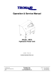
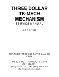
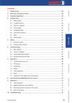
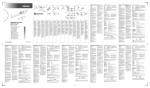
1
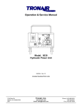
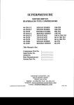
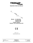
Operation & Service Manual Model: 01-0505-0000 Falcon 10/20/100/200 Multi-Head 02/2007 − Rev. 02 **When ordering replacement parts/kits, please specify model, serial number and color of your unit.** 1740 Eber Rd Holland, OH 43528-9794 USA Tronair, Inc. www.tronair.com Email: [email protected] Phone: (419) 866-6301 800-426-6301 Fax: (419) 867-0634 REVISION 02 DATE 02/2007 TEXT AFFECTED Major Revision Model: 01-0505-0000 Falcon 10/20/100/200 Multi-Head TABLE OF CONTENTS PAGE 1.0 1.1 2.0 2.1 3.0 3.1 3.1.1 3.1.2 3.2 3.2.1 4.0 4.1 4.2 4.3 5.0 5.1 5.2 6.0 7.0 DESCRIPTION .............................................................................................................................................................. 1 SPECIFICATIONS ..................................................................................................................................................... 1 SAFETY INFORMATION............................................................................................................................................... 1 GENERAL .................................................................................................................................................................. 1 OPERATION.................................................................................................................................................................. 1 PRELIMINARY CHECKLIST ...................................................................................................................................... 1 Head Attachment Weldment ...................................................................................................................................... 1 Sliding Pin .................................................................................................................................................................. 1 USAGE PROCEDURE ............................................................................................................................................... 1 Multi-Head Attachment ............................................................................................................................................... 1 TRAINING...................................................................................................................................................................... 2 TRAINING REQUIREMENTS .................................................................................................................................... 2 TRAINING PROGRAM............................................................................................................................................... 2 OPERATOR TRAINING ............................................................................................................................................. 2 PROVISION OF SPARES ............................................................................................................................................. 2 SPARE PARTS .......................................................................................................................................................... 2 PARTS LISTS & ILLUSTRATIONS ............................................................................................................................ 2 IN-SERVICE SUPPORT ................................................................................................................................................ 2 GUARANTEES/LIMITATION OF LIABILITY ................................................................................................................ 2 02/2007 | Rev. 02 Model: 01-0505-0000 Falcon 10/20/100/200 Multi-Head Tronair towbars/heads must only be used with matching Tronair heads/towbars, and Tronair shear pins. This product can not be modified without the written approval of Tronair, Inc. Any modifications done without written approval voids all warranties and releases Tronair, Inc., it suppliers, distributors, employees, or financial institutions from any liability from consequences that may occur. Only Tronair OEM replacement parts shall be used. 1.0 DESCRIPTION The Tronair Model 01-0505-0000 Multi-Head Towbar is a towbar head attachment for the Falcon 10/20/100/200 Aircraft manufactured by Dassault. The towbar head attachment is designed for use with Tronair Multi-Head Towbar Model 01-1202-0000 for towing the previously stated aircraft. The towbar head attachment uses a sliding pin/stationary pin arrangement to interface with the aircraft tow point. 1.1 SPECIFICATIONS Aircraft Application: Falcon 10/20/100/200 manufactured by Dassault Maximum Aircraft Gross Weight: 30,000 lbs (13,608 kg) Dimensions: Length: 4.937 in (37.9 cm) Width: 10 in (25.4cm) Height: 4.59 in (11.66 cm) Weight: 30 lbs (13.6 kg) Finish: Blue Powder Coat 2.0 SAFETY INFORMATION 2.1 GENERAL The Tronair Model 01-0505-0000 Towbar Head Attachment is used for towing the DassaultFalcon 10/20/100/200 Aircraft only. To ensure safe operation, please read the following statements and understand their meaning. This manual contains safety precautions, which are explained as follows. Please read carefully. WARNING! Warning is used to indicate the presence of a hazard that can cause severe personal injury, death, and/or substantial property damage if the Warning Notice is ignored. CAUTION! Caution is used to indicate the presence of a hazard, which will or can cause minor personal injury or property damage is the Caution Notice is ignored. WARNING! A damaged or bent towbar should not be used. Towbar should be repaired or replaced. 3.0 OPERATION 3.1 3.1.1 PRELIMINARY CHECKLIST Head Attachment Weldment Check weld between connector tube and head plate for cracks. Check weld between side rails and head plate for cracks. Check weld between side rail and stationary pin for cracks. Check weld between side rail and sliding pin sleeve for cracks. 3.1.2 3.2 3.2.1 Sliding Pin Check sliding pin for bending or excessive wear. Ensure sliding pin slides freely. Check sliding pin ball lok-T pin. Ensure ball lok-T pin is securely attached to the head attachment via its lanyard. Ensure ball lok-T pin is not loose or missing. USAGE PROCEDURE Multi-Head Attachment Secure the towbar head attachment using the ball lok-T pin (supplied with the multi-head towbar) onto the Tronair 011202-0000 Multi-Head. Ensure the sliding pin is locked in place using the ball lok-T pin. CAUTION! It is recommended that your towbar be attached to the aircraft first, and then connected to the tug to avoid possible aircraft damage. 02/2007 | Rev. 02 Page | 1 Model: 01-0505-0000 Falcon 10/20/100/200 Multi-Head 4.0 TRAINING 4.1 TRAINING REQUIREMENTS The employer of the operator is responsible for providing a training program sufficient for the safe operation of the towbar. 4.2 TRAINING PROGRAM The employer provided operator training program should cover safety procedures concerning use of the towbar in and around the Falcon 10/20/100/200 at the servicing location. 4.3 OPERATOR TRAINING The operator training should provide the required training for safe operation of the towbar. NOTE: Maintenance and Trouble Shooting are to be performed by the skilled and trained technician. 5.0 PROVISION OF SPARES 5.1 SPARE PARTS Spare parts may be obtained from the manufacturer: TRONAIR, Inc. Telephone: (419) 866-6301 or 800-426-6301 1740 Eber Road Fax: (419) 867-0634 Holland, Ohio 43528-9794 USA E-mail: [email protected] Website: www.tronair.com 5.2 PARTS LISTS & ILLUSTRATIONS Reference the following page for Replacement Parts and Kits available. 6.0 IN-SERVICE SUPPORT Contact Tronair for technical services and information. 7.0 GUARANTEES/LIMITATION OF LIABILITY Tronair products are warranted to be free of manufacturing or material defects for a period of one year after shipment to the original customer. This is solely limited to the repair or replacement of defective components. This warranty does not cover the following items: a) Parts required for normal maintenance b) Parts covered by a component manufacturers warranty c) Replacement parts have a 90-day warranty from date of shipment If you have a problem that may require service, contact Tronair immediately. Do not attempt to repair or disassemble a product without first contacting Tronair, any action may affect warranty coverage. When you contact Tronair be prepared to provide the following information: a) Product Model Number b) Product Serial Number c) Description of the problem If warranty coverage is approved, either replacement parts will be sent or the product will have to be returned to Tronair for repairs. If the product is to be returned, a Return Material Authorization (RMA) number will be issued for reference purposes on any shipping documents. Failure to obtain a RMA in advance of returning an item will result in a service fee. A decision on the extent of warranty coverage on returned products is reserved pending inspection at Tronair. Any shipments to Tronair must be shipped freight prepaid. Freight costs on shipments to customers will be paid by Tronair on any warranty claims only. Any unauthorized modification of the Tronair products or use of the Tronair products in violation of cautions and warnings in any manual (including updates) or safety bulletins published or delivered by Tronair will immediately void any warranty, express or implied. The obligations of Tronair expressly stated herein are in lieu of all other warranties or conditions expressed or implied. Any unauthorized modification of the Tronair products or use of the Tronair products in violations of cautions and warnings in any manual (including updates) or safety bulletins published or delivered by Tronair will immediately void any warranty, express or implied and Tronair disclaims any and all liability for injury (WITHOUT LIMITATION and including DEATH), loss or damage arising from or relating to such misuse. 02/2007 | Rev. 02 Page | 2 Model: 01-0505-0000 Falcon 10/20/100/200 Multi-Head Parts List **When ordering replacement parts/kits, please specify model, serial number and color of your unit.** Item 1 Part Number Description Z-1383-01 Weldment, Head 5/32" Qty G-1300-16100 Roll Pin, K-1124 Kit, Adapter Set Replacement; consists of: 2 G-1202-1075 Stopnut, 3/8 -24 Elastic 6 4 J-2664 Adapter, Axle 1 5 G-1250-1070N Flatwasher 3/8 Narrow 12 6 G-1100-107516 Bolt, Hex Head, Grade 5, 3/8 -24 x 1 ¾" long 6 10 G-1300-19040 Roll Pin, 3/16" diameter x ½" long 1 11 J-2663 Adapter, Axle 1 12 diameter x 1" long Not Sold Separately 1 K-1125 Kit, Axle Locking Mechanism Replacement; consists of: 3 H-1205 Cover, Handle 1 7 Z-0019 Weldment, Axle Locking 1 8 G-1300-16050 Roll Pin, 5/32" diameter x 5/8 " long 1 9 G-1300-25340 Roll Pin, ¼" diameter x 3 ½" long 1 02/2007 | Rev. 02 Page | 3 APPENDIX - I Ins-1582 Towbar Usage Instructions INS-1582 Towbar Usage Instructions 11/2003 – Rev. 03 1740 Eber Rd Holland, OH 43528-9794 USA Tronair, Inc. www.tronair.com Email: [email protected] Phone: (419) 866-6301 800-426-6301 Fax: (419) 867-0634 REVISION 03 DATE 11/25/03 TEXT AFFECTED pg 1 Warning added INS-1582 Towbar Usage Instructions Your Tronair towbar is engineered and built to the highest standards of quality and workmanship. Under normal usage and with minimal maintenance this towbar will provide exceptional service. WARNING! A damaged or bent towbar should not be used, but should be repaired or replaced. Using a damaged or bent towbar can result in aircraft or equipment damage and possible personal injury. WARNING! Towbars With Hydraulic Lifting Mechanism: The hydraulic lift mechanism (on those towbars so equipped) should only be used to raise the towbar to facilitate connection to the aircraft or tug. Release any hydraulic pressure when towing aircraft or moving towbar. WARNING! Towbars Should be Used with Category 1 Tugs: Tronair recommends the use of a towbar with a category 1 or category 2 tug and aircraft not exceeding 75,000 lbs gross weight. Using the towbar with aircraft weighing in excess of this specific limitation may result in excessive loads and stresses being applied to the towbar and/or the aircraft. These excessive loads may cause failure of the towbar which could cause damage (INCLUDING WITHOUT LIMITATION to the aircraft) and/or personal injury OR DEATH. TRONAIR MAKES NO REPRESENTATION, WARRANTY OR GUARANTEE AS TO SUCH MISUSE AND DISCLAIMS ANY AND ALL LIABILITY FOR INJURY, LOSS OR DAMAGE ARISING FROM OR RELATING TO SUCH MISUSE. 11/2003 | Rev. 03 Page | 1 INS-1582 Towbar Usage Instructions (If Applicable) FIGURE 2 NOTE: Typical towbar. Your towbar and/or head may not have all of the features shown FIGURE 1 NOTE: Typical towbar. Your towbar and/or head may not have all of the features shown 11/2003 | Rev. 03 Page | 2 INS-1582 Towbar Usage Instructions BEFORE USING TOWBAR, COMPLETE THE FOLLOWING CHECKLISTS: Reference Figures 1 & 2 on Page 2. TOWBAR: Area of Towbar: Shock Assembly: Check: 1. Weld between eye and tube (Are there cracks?) 2. Bolts attaching shock to towbar (Loose, missing, stripped, etc.) 3. Eyebolt (Is it bent, worn down, or deformed? Towbar Weldment: 2. 1. Tube (Is it bent, dented, bowed, and/or have cracks?) Weld at head end (Are there any cracks in the welds?) 3. Head hole (Is it elongated? Is the ball lok pin attached to the towbar?) Caster/Skid Plate: 1. 2. 3. Casters (Are they missing or bent?) Handles (Are they broken, bent, or missing?) Bolts (Are they missing or loose?) Wheel Assembly: 1. 2. Wheels (Are they flat? Is the rim bent?) Axle (Is it bent?) HEAD: Area of Head: Bolts & Lanyards: Check: 1. Are they loose, missing, or stripped? Are they attached to the head? Weldment: 1. 2. Welds holding side rails to head rail (Are there any cracks?) Shear Plates (Are there cracks in welds? Are the plates bent?) Shear Pin Mechanism: 1. 2. 3. Shear Pin (Is it bent or deformed? Are there spares?) Bushings (Are they cracked, chipped, secure?) Pivot Bolt (Are the nuts tight? Are there washers present?) Area of Head: Aircraft Attach Point: Check: 1. Sliding Pin(s) (Are they bent, cracked? Do they slide freely?) 2. Locking Pin (Are they loose? Do they hold the sliding pins securely?) 3. Wear sleeves (Are the welds cracked?) 4. Roll Pins(s) (Are they rusted? Are they missing? Are they loose?) 5. Ball Lok Pin (Is it attached to head? Is it rusted? Is it bent?) 6. Axle Adapter (Is it bent? Is the slot deformed? Are bolts tight?) SNAP-BAK AND UNIVERSAL TOWBARS: Area of Towbar: Check: Towbar: 1. Spring (Has it taken a set? Loose in the assembly?) 2. Eyebolt (Is it bent, worn down, or deformed?) 3. Tube (Is it bent, dented, bowed, or cracked? Is it rusted badly?) 4. Welds (Are there any cracks in the welds?) 5. Head Hole (Is it elongated? Is the bolt attached correctly?) Function: 1. Does it snap back? Head: 1. 2. 3. 4. 5. Pivot Bolt (Is it present along with washers? Is the nut tight? Is it rusted?) Roll Pin(s) (Are they rusted? Are they missing? Are they loose?) Weldment (Is it deformed, bent, or rusted beyond reasonable use?) Lanyard (Is it attached to weldment?) Sliding Pin(s) (Are they bent, cracked or rusted? Does it slide?) 11/2003 | Rev. 03 Page | 3 INS-1582 Towbar Usage Instructions USAGE PROCEDURE Aircraft Attachment: It is recommended that your towbar be attached to the aircraft first, and then connected to the tug to avoid possible aircraft damage. Ensure sliding pins are locked in place before towing aircraft. Tug Attachment: Damage to the towbar or aircraft can result from an excessive towbar angle during towing operations (Reference to Figure 3). If aircraft with both high and low tow points are encountered, consider using two pintle hooks, as shown in Figures 4 & 5, so that the towbar is as level as possible during towing. Also pintle hook height should prevent contact of towbar wheels with the ground, during towing. (Reference Figure 5). FIGURE 3 - INCORRECT FIGURE 4 - CORRECT FIGURE 6 FIGURE 5 - CORRECT Type Of Coupler: Damage to the towbar or aircraft can result while towing with the following type of couplers: - Lift Head Standard Duty Latch - Vertical Side Swing Latch Swivel Hook These types of couplers are known to cause binding and failure in the eyebolt. Indicators of eyebolt binding are wear on the outside diameter of the eye and indentations on the inside diameter. The failure will begin at the head of the eye. See Figure 6. 11/2003 | Rev. 03 Page | 4 INS-1582 Towbar Usage Instructions USAGE PROCEDURE (continued) Type Of Coupler: Damage to the towbar or aircraft can result while towing with the following type of couplers: - Lift Head Standard Duty Latch - Vertical Side Swing Latch Swivel Hook These types of couplers are known to cause binding and failure in the eyebolt. Indicators of eyebolt binding are wear on the outside diameter of the eye and indentations on the inside diameter. The failure will begin at the head of the eye. See Figure 6. Figure 7 illustrates a pintle hook arrangement that is known to eliminate eyebolt binding. Tronair recommends using this type of hook on your tug. FIGURE 7 FIGURE 8 Eyebolt and Pintle Pin Size: Damage to the towbar or aircraft can result by towing or pushing an aircraft with an incorrect size eyebolt or pintle pin. A correct size eyebolt will make contact with the pintle pin. A gap between the eyebolt outside diameter and the coupler face plate should be easily seen. An eyebolt which is too large will cause the eyebolt to make contact with the face plate of the coupler. When the eyebolt is too large for the coupler, a gap between the inside diameter of the eyebolt and the coupler face plate will be seen. See Figure 8. To ensure proper towing and pushing, check to make sure that the pintle pin diameter is not too large for the eyebolt's inside diameter. Approximately a one-half inch (1/2") gap between the pin diameter and the eyebolt should be seen. If any of these conditions are not met, please contact Tronair for information to obtain a new coupler. Towing Angle: Damage to the towbar or aircraft can result from pushing an aircraft while maintaining too sharp of an angle between the tug and the towbar. Contact between the towbar weldment and tug must be avoided. It is recommended that the angle between the tug and towbar not exceed 90º. See Figure 9. FIGURE 9 11/2003 | Rev. 03 Page | 5 APPENDIX - II Declaration of Conformity DECLARATION of CONFORMITY The design, development and manufacture is in accordance with European Community guidelines Multi-Head 01-0505-0000 Relevant provisions complied with by the machinery: 2006/42/EC Relevant standards complied with by the machinery: EN ISO 12100-1 Identification of person empowered to sign on behalf of the manufacturer: Quality Assurance Representative 1740 Eber Rd Holland, OH 43528-9794 USA Tronair, Inc. www.tronair.com Email: [email protected] Phone: (419) 866-6301 800-426-6301 Fax: (419) 867-0634