1
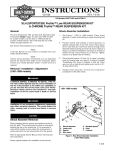
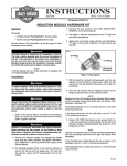
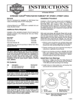
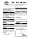
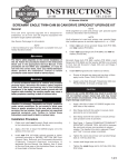
INSTRUCTIONS
-J01754
®
REV. 8-23-00
Kit Number 94667-00
CAM SUPPORT PLATE OIL CONTROL KIT
General
i03240.eps
This kit is designed to fit 1999 and later Twin Cam 88™
engines.
Kit contents:
DESCRIPTION
Screw, Self-Tapping
Washer, Sealing
O-Ring
PART No.
3844
31433-84A
11301
NOTE
A Service Manual for your vehicle is available from
your Harley-Davidson Dealer.
1WARNING
A SERVICE MANUAL IS NEEDED TO INSTALL THIS KIT.
The rider's safety depends upon the correct installation of
this kit. If the procedure is not within your capabilities or
you do not have the correct tools, have your HarleyDavidson dealer perform the installation. Improper
installation of this kit could result in death or serious
injury.
Installation
Figure 1. Right Crankcase Half -99
i03241.eps
1WARNING
To protect against shock and accidental start-up of vehicle, disconnect the battery cables, negative cable first,
before proceeding. Inadequate safety precautions could
result in death or serious injury.
Boss
1WARNING
Always disconnect the negative battery cable first. If the
positive battery cable should contact ground with the
negative cable installed, the resulting sparks may cause a
battery explosion which could result in death or serious
injury.
1.
Disconnect the battery cables, negative battery cable first.
2.
Refer to the applicable Service Manual and remove the
cam support plate.
3.
Refer to Figures 1 and 2. Examine the right crankcase
half and note the addition of a boss on the -99A
crankcase.
4.
Figure 2. Right Crankcase Half -99A
If the boss is present, as shown in Figure 2, install the Oring from the kit into position in the groove of the boss.
Then install the cam support plate following instructions
in the applicable Service Manual.
1 of 2
NOTE
i01743
If you are installing a 1999 cam support plate as shown in
Figure 5, no modification of the plate is required.
CAUTION
Screw
Do not install the screw and washer into the 2000 cam plate
if the boss is present in the crankcase. If a screw and
washer are installed with the boss and O-ring present in
crankcase, when the cam plate is installed and tightened
the crankcase/cam plate will be damaged.
5.
If you are using the 2000 cam support plate as shown in
Figure 3, and the boss is not present on the crankcase as
shown in Figure 1, proceed as follows:
Washer
NOTE
Once the screw and washer are installed, they are not to be
removed.
a.
See Figures 3 and 4. Install screw and washer into
proper hole of the cam support plate, as shown. Use
LOCTITE THREADLOCKER 242 (blue) and torque
screw to 35-55 in-lbs. (13.6-16.3 Nm).
b.
Install cam support plate using the procedures from
the applicable Service Manual.
1WARNING
Always connect the positive battery cable first. If the positive
cable should contact ground with the negative cable
installed, the resulting sparks may cause a battery explosion
which could result in death or serious injury.
6.
Figure 4. Cam Support Plate - 2000
i01742
Reconnect the battery cables, positive battery cable first.
i01750
Figure 5. Cam Support Plate - 1999
Cam Support Plate
Washer
Screw
Figure 3. Cam Support Plate - 2000
-J01754
2 of 2