1
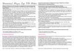
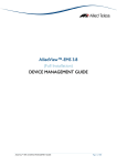
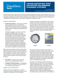
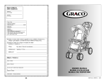
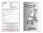
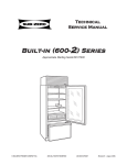
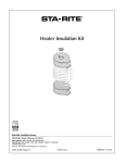
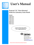
MCF DUST FILTER INSTALLATION, OPERATION & MAINTENANCE MANUAL MAC EQUIPMENT, INC. P.O. BOX 205 SABETHA, KS 66534 SALES, PARTS & SERVICE: 1-888-821-2476 www.macequipment.com Publication: MAN3001E Revision Date: 11/10/05 LIST OF FIGURES TABLE OF CONTENTS DESCRIPTION Page Figure 1-1 Typical MCF Dust Filter.......................................... 1 PAGE General Introduction.................................................................. 1 Safety......................................................................................... 1 Principle of Operation................................................................ 3 Installation.................................................................................. 4 System Start-Up & Operation ................................................... 12 Maintenance .............................................................................. 12 Troubleshooting......................................................................... 18 Spare Parts................................................................................ 19 Figure 2-1 Lockout and Tagout of Electrical Service and Compressed Air .................. 1 Figure 2-2 Typical Location of Safety Decals ......................... 2 Figure 2-3 Typical Locations of Safety Decals For Explosion Vents .............................................. 3 Figure 3-1 Principle of Operation............................................. 3 Figure 4-1 Typical Support Structure....................................... 4 Figure 4-2 Typical High Entry Inlet .......................................... 4 Figure 4-3 Typical Front Access Service Platform and Ladder Assembly.............................. 5 Figure 4-4 Typical Side and Front Access Service Platform and Ladder Assembly................. 5 Figure 4-5 Typical PVC Style Explosion Vent......................... 5 Figure 4-6 Typical Rupture Style Explosion Vent ................... 6 Figure 4-7 Location of Ductwork and Accessories ................. 6 Figure 4-8 Discharge Auger Assembly.................................... 6 Figure 4-9 Pump Package ....................................................... 6 Figure 4-10 Installation of Differential Pressure Gauge.......... 7 Figure 4-11 Jumpers and Wiring of the Photohelic Switch/Gauge ....................................................... 7 Figure 6-1 Typical Cross Section of Cleaning Mechanism.. 13 Figure 6-2 Typical Distribution Arm Detail............................ 13 Figure 6-3 Typical MCF Index Sensor.................................. 14 Figure 6-4 Typical Alignment Illustration .............................. 14 Figure 6-5 Typical MCF Larger Diaphragm Details ............. 14 Figure 6-6 Typical Tightening Sequence.............................. 15 Figure 9-1 Typical Cleaning Mechanism.............................. 20 It is the owner's responsibility to maintain the safety features included with this equipment. The safety features may include, but not necessarily be limited to: guards, access doors and covers, explosion vents, warning decals, caution decals, and advisory decals. Replacement safety features are available from MAC Equipment, Inc. DO NOT attempt to operate this equipment until you have read and understood the contents of this manual. If you do not understand the contents of the manual bring it to the attention of your supervisor. This manual contains important safety instructions concerning the maintenance, use, and operation of this product. Failure to follow these instructions may result in serious injury or death. NO haga funcionar este equipo hasta haber leido y comprehendido el contenido de este manual. Si aiguna partre del contenido del manual queda sin comprehender, notifiqueselo a su supervisor. Este manual contiene instrucciones importantes en cuanto al anterimiento, uso, y funcionamiento sequros de este producto. El no seguir las instrucciones contenidas en este manual podria ocasionar lesiones graves. Warning Decals And Guards GENERAL INTRODUCTION Congratulations on your selection of a MAC MCF Dust Filter. As the owner/operator of this unit you have an important responsibility to see that it is operated and maintained in a safe manner. The unit will require very little attention to keep it in good operating condition. This manual has been prepared to aid you in that effort. This piece of equipment contains several warning decals located in many different locations. It is the owner/operator’s responsibility to maintain the integrity of these decals and to ensure that all operators of the equipment are aware of them and understand their meaning. Replacement decals are available free of charge from your MAC Equipment Service Representative, or by calling MAC Equipment Inc. at 1-888-821-2476. This piece of equipment may contain one or more safety guards to protect the operator(s) from injury. It is the owner/operator’s responsibility to maintain the integrity of these guards and ensure that they are in place when the equipment is in operation. Throughout this manual, reference may be made to various components which may or may not be part of your particular system. They are included in the interest of fully describing typical MCF filter systems. DO NOT attempt to operate this equipment with any guard removed. Replace damaged guards. Lockout-Tagout Requirements Before inspecting or servicing this equipment perform an approved lockout-tagout procedure on the electrical service, the compressed air (or other gas) supply, or any other energy source. Figure 1-1 Typical MCF Dust Filter Receiving Your Equipment As soon as the equipment is received, it should be carefully inspected to make certain the unit is in good condition and all items listed on the packing list are received. Even though the equipment is mounted on heavy shipping skids at our plant it is possible for it to be damaged in shipment. All damages or shortages should be noted on the Bill of Lading. The purchaser must take immediate steps to file reports and damage claims with the carrier. All damages incurred to the unit in transit are the responsibility of the common carrier since it is the policy of MAC Equipment, Inc. to make shipment F.O.B. from its factory. Ownership passes to purchaser when the unit is loaded and accepted by carrier. Any claims for in transit damage or shortage must be brought against the carrier by the purchaser. If the unit is not going to be assembled and installed soon after arrival, it should be stored in a warm, dry location to protect against corrosion. Filter bags and cages or cartridges must be stored in a dry, rodent proof location. ELECTRICAL POWER COMPRESSED AIR OR GAS Figure 2-1 Lockout and Tagout of Electrical Service and Compressed Air (or other gas) SAFETY INFORMATION WARNING! Do not attempt to operate or maintain this piece of equipment until you have read and thoroughly understood all of the safety information contained in this manual. All such information must be taken seriously. This piece of equipment contains moving parts and potential pinch points which can cause serious injury or death. If you do not understand anything in this manual seek assistance from your supervisor before operating this equipment. Control of this equipment must be in accordance with OSHA Standard 1910.147 "The control of hazardous energy (lockout-tagout)". This standard "requires employers to establish a program and utilize procedures for affixing appropriate lockout devices or tagout devices to energy isolating devices and to otherwise disable machines or equipment to prevent unexpected energizing, startup or release of stored energy in order to prevent injury to employees". For further information on Lockout-Tagout requirements, see your company's Safety Director or refer to OSHA Standard 1910.147. Safety Precautions Do not operate, inspect, or service this equipment unless all the following safety precautions are in effect: Recognize Safety Information The symbol at left is used to alert you to important safety messages located throughout this manual. It also appears on the equipment to alert you to potential hazards. When you see this symbol you must read, understand, and heed the information that accompanies it. Guards, access doors, and covers are in place and secure. The equipment has been wired and grounded in accordance with all applicable codes. Understand Signal Words DANGER ! Indicates an imminently hazardous situation which, if not avoided, will result in death or serious injury. WARNING ! Indicates a potentially hazardous situation which, if not avoided, could result in death or serious injury. CAUTION ! Indicates a potentially hazardous situation which, if not avoided, may result in minor or moderate injury and/or property damage. Publication: MAN3001E If air being filtered contains toxic materials all necessary precautions to protect personnel have been taken. An approved lockout-tagout procedure has been followed before the equipment is inspected, disassembled, and/or serviced. The equipment is automatically controlled and may start without warning unless energy supplies are properly disconnected and locked out-tagged out. The control panel enclosure is closed and secured except as is necessary for service or adjustment. The service door is closed and secured. Do not enter filter while the system exhaust fan is operating; air flow can pull service door closed, trapping personnel inside. A confined space permit, if required by authorities having jurisdiction, has been obtained prior to personnel entering the unit. Check with your company’s safety director for special instructions, testing prior to entry, etc. that may be required by the specific application. MAC Equipment, Inc. 1 Explosion vents have been properly installed and ducted, as described below in the Installation section. MAC PVC style explosion vents are shipped (when ordered) with (4) steel bolts. These bolts must be replaced with special plastic bolts before operating the filter. B. Equipment has moving blades, shaft, rotor or arm which may cause injury. It may also have valves discharging compressed gases. Do not cut, weld or grind on the filter while it is in operation; dust laden air may be highly explosive. Refer to the proper National Fire Protection Association Manual for information on cutting, welding or grinding in hazardous areas. The work area is clean and orderly, free of debris, materials, tools, etc. Operating personnel are wearing proper ear and eye protection and have secured loose hair, clothing, jewelry, etc. C. Failure to follow these instructions may result in death, personal injury, and/or property damage! Equipment can start without warning. Exhaust fan can create enough force to close and hold service door closed. Installation and Operation Cautions The MCF Cleaning arm timing is critical to the correct and efficient operation of these filters. Refer to the maintenance section for correct placement and adjustment of the timing. BLOWERS and GEAR BOXES are shipped without lubrication oil, do not operate before lubricating. Refer to the maintenance section for the lubrication schedule. All system piping must be clean internally before connecting to blower. Check lubrication level only when the equipment is stopped. Keep inlet filter clean. Keep belts properly tensioned and aligned. Keep pressure relief valves in good condition so that maximum pressure is not exceeded. D. Typical MAC Equipment, Inc. nameplate. E. Typical MAC Equipment, Inc. MCF Filter Patent Numbers F. Equipment can start without warning. Cleaning Mechanism rotation can cause entrapment under cleaning arm which will induce serious injury. Never attempt to regulate air flow by restricting intake or exhaust of a positive displacement blower. NOTE: Full rated pressure is full pressure differential from inlet flange to discharge flange. Read and Understand Safety Decals Several safety labels are located on this piece of equipment to warn the operator(s) of potentially hazardous situations. Decal Locations The following figure shows typical locations for safety decals on the MCF filter. The locations of decals for your particular filter may vary from those indicated. Inspect your filter for locations of all decals. F G C A B D E D Typical MAC Equipment logo L G. H K J G M I or N H. B G Equipment must rotate in direction indicated on rotation arrow. O Figure 2-2 Typical Locations of Safety Decals (see next page for description of decals) I. Safety Decals Safety decals (and other information labels) may include, but are not necessarily limited to, the examples shown below. Locate all of the safety decals on your equipment and know their meaning prior to operating this dust filter. Free replacement decals are available; ask for decal kit P/N 413468. Equipment has rotating screw conveyor which may cause injury. Operate only when covers are in place. A. End User must determine hazard level for entry permit requirements. Publication: MAN3001E MAC Equipment, Inc. 2 J. Disconnect, lockout and tagout electrical and all other energy sources before inspecting, cleaning or performing maintenance on this filter. Equipment may be remotely controlled. K. Moving drive components can cause injury. L. This warning sign reminds operators and other users that they must read and understand the Operator Manual before storing, installing, inspecting, cleaning or servicing the filter. This filter may be remotely controlled. It can start without warning unless it is properly locked out at the motor starter or local disconnect. Do not rely on the control system for safe lockout. Check lubricant level before initial startup. M. Do not weld or flame cut on silencer. May cause packing to enter into air stream and cause damage to cleaning mechanism. Equipment can start without warning. This access port should be equipped with safety lock. N. Moving blades will cause severe injury. PRINCIPLE OF OPERATION The MCF filter is a top bag removal, pneumatically controlled, medium pressure high volume pulse cleaning dust filter. Cleaning air is generated by a positive displacement blower. MCF models range in size from a MCF112 with 1,086 sq. ft. of cloth to a MCF494 with 7,163 sq. ft of cloth. O. Do not operate equipment with guards removed. In addition, if your filter is equipped with an explosion vent the following figure shows typical locations for other safety decals. RUPTURE STYLE EXPLOSION VENT I PVC STYLE EXPLOSION VENT H I I I Figure 2-3 Typical Locations of Safety Decals for Explosion Vents H. Never use steel bolts in the explosion vent panel. Steel bolts will not allow the vent to function as designed Air Flow through the Unit Stay clear of explosion vent. During an explosion, flame, explosive gases or flying material will be released. Dust laden air enters the MCF through the tangential inlet near the bottom of the unit. A remote fan on the exhaust side draws air through the filter. A majority of the dust entering the unit is captured by the spiral and directed into the hopper and out the discharge. The remaining dust laden air is directed to the filter bags. Vortex baffles just below the filter bags straighten the air to prevent excessive wear on the bags. Filtered dust collects on the outside of the filter media. The MPHV cleaning mechanism pulses the dust off the filter bags and it drops into the hopper. Filtered air passes through the center of the filter bags and out through the clean air discharge at the top of the unit. I. Figure 3-1 Principle of Operation MPHV Cleaning The following ISO decals may appear on your MCF Filter: Publication: MAN3001E The MCF filter is a continuously operating self-cleaning filter. It uses MEDIUM PRESSURE HIGH VOLUME (MPHV) air to clean the bags. This air is supplied from a positive displacement blower located outside the unit. Cleaning air is stored in a tank within the clean air plenum. Cleaning air pressure climbs to approximately 7 psi within this tank before it is injected into the bags. A high volume blast of air is delivered by means of the MAC diaphragm valve. Cleaning air is channeled MAC Equipment, Inc. 3 to the bags through a rotating arm. The cleaning arm has a series of nozzles correlated to the tube sheet layout. Cleaning air exits these nozzles and enters the bags. This action cleans the bags by; (1) creating a shock wave that pops the bag, and (2) forcing a momentary reverse flow of air through the bags. SPLICE PLATE TOP CHANNEL MCF Timing The unique feature of the MCF filter is its patented timing mechanism. Once adjusted, this device assures a blast of cleaning air is injected directly into the center of the bag, regardless of the rotational speed of the cleaning arm. This device is mechanical and does not require electrical power to internal solenoids for firing. Through the proper selection of gear ratios and rotational speeds the cleaning frequency can be adjusted. COLUMN CROSS BRACING Positive Displacement Blower The MCF Filter requires a rotary positive displacement blower to supply the cleaning air. This blower has two figure-eight impellers rotating in opposite directions. As the impeller lobes pass the blower inlet, they trap a quantity of air. This entrapment occurs four times per revolution, moving the entrained air around the case to the blower outlet. Timing gears accurately position the impellers in relation to each other, maintaining the minute clearances so vital to the high volumetric efficiency of the rotary positive displacement blower. For further information on this equipment refer to the appendix. Variable Cleaning Control Options: Air Diverter Valve The Air Diverter Valve (ADV) cleaning cycle control is offered as an option on the MAC MCF filters. This valve provides an economical method of controlling the cleaning cycle of the filter. The cleaning cycle can be extend from the base time to any cycle time desired above this base. This is useful for filter applications that require a longer duration between cleaning pulses, to prevent over-cleaning the filter media. To extend the cleaning cycle with the ADV, a timer, Photohelic gauge, or PLC is required. The ADV functions as a by-pass valve to the cleaning system. To initiate cleaning the valve is closed and air is allowed to flow to the cleaning mechanism. The valve is left closed for the duration of one cleaning cycle. To interrupt the cleaning cycle the valve is opened and cleaning air is exhausted to the atmosphere. The frequency of the cleaning cycle is controlled by adjusting the duration of the open state of the valve. Figure 4-1 Typical Support Structure To install the support structure: 1. Review the components of the support structure. 2. Set anchor bolts in the foundation according to the plan drawing. Position four columns on anchor bolts as indicated. Install nuts but do not tighten. 3. Attach cross bracing to (4) sides with grade A325, ¾” UNC (as provided) bolts, washers, and nuts. 4. On 10 ft., 12 ft., 13 ft., and 14 ft. diameter filters, bolt halves of top channel frame together with grade A325, ¾“ UNC bolts (as provided), washers, nuts, and splice plate both sides of channel. 5. Lift channel frame onto columns and bolt together with grade A325, ¾” UNC (as provided) bolts, wedge washers, flat washers, and nuts. 6. Check the structure is square and plumb. 7. Tighten all bolts. Bolts must be tightened before allowing the structure to support the weight of the filter. 8. Touch-up paint on the support structure as needed. Assembly should be complete and all bolts tightened prior to painting. High Entry Inlet This inlet may be mounted with the filter horizontal. Variable Frequency Drives Variable Frequency Drives (VFD) are offered as an alternate option for cleaning-cycle control on the MAC MCF Filters. This arrangement controls the speed of the rotating cleaning arm and blower, which directly controls the frequency of the cleaning cycle. Cleaning frequency, is adjustable above and below the base cycle. The extent of control is limited by the physical limitations of the drive and the motor. With this type of control, the filter is usually provided with a non-standard base cleaning cycle, falling in the center of the desired adjustment range. Refer to MAC Engineering Department for further details. To install the high entry inlet: 1. Remove the bolted shipping cover from the high entry inlet opening. 2. Apply a bead of silicone caulk around the inlet assembly flange. Lift inlet into position and bolt with 1/2-13 x 1" lg. bolts with flat washers. NOTE: The sloped end of the inlet assembly must be toward the filter bottom Air Exhaust Returning filtered exhaust air into a facility can present hazards. The type of dust, it’s characteristics and the effect of a recirculation system malfunction must be considered. If system design dictates that filtered air be returned into the facility, the buyer is cautioned to take appropriate steps to monitor the air quality and provide appropriate safeguards as prescribed by OSHA, NFPA, Federal, State and Local codes and regulations. FILTER HOUSING SILICON E CAULK Never return filtered air to a habitable space or building without proper monitoring and precautions. R EMOVE SHIPPING C OVER INSTALLATION Figure 4-2 Typical High Entry Inlet The MCF filter housing and internal components are shipped factory assembled. The support structure (if provided), magnehelic or photohelic pressure gauges, bags and cages, service platform and ladder/safety cage are shipped loose and require field assembly. Location With the inlet mounted the filter will be unbalanced when lifted to the vertical position. Locate the MCF filter in a clear area away from normal personnel traffic on a flat and solid concrete or steel surface. Locate the filter so as to minimize supply and exhaust ductwork and so that explosion venting, if required, can be directed so that injury to personnel and damage to property cannot occur. Provide sufficient space for emptying the hopper and maintaining the unit. Tangential Inlet The tangential inlet requires only the addition of the fourth side of the inlet flange. During an explosion, a vent will release flame, explosive gases or flying material. The explosion venting must be directed away from personnel to prevent injury. To install the tangential inlet angle: Foundation The filter requires an adequate foundation, designed by a qualified structural engineer. Refer to the General Dimension drawings of your system for foot pad layout and weights. When calculating the loading for the foundation, the weight of the filter, material collected, and all auxiliary equipment must be considered together with snow, wind and seismic loads. Support Structure A support structure may be supplied by MAC Equipment, Inc. as part of your MCF filter system. The figure below shows a typical structure, which will vary from system to system depending on the size of the MCF filter. Publication: MAN3001E 1. Locate a 2-1/2" x 2-1/2" angle with bolt holes in both legs. One leg will match the bolt pattern drilled into the outside of the inlet. 2. Apply a bead of silicone caulk and bolt the angle in place with 1/2-13UNC x 1" lg. bolts with flat washers. Service Platform (see figure 4-3 and 4-4) Platform may be mounted with the filter horizontal. To install the front access service platform: (see figure 4-3) 1. Align holes in service platform with holes in platform adapter located below service door. 2. Bolt together with ½”UNC (as provided) bolt, nuts, and lock washers. 3. Position support clips over holes with weld-ons on both sides of service door and secure in position with ½”UNC (as provided) bolts and lock washers. 4. Attach (2) flat bar supports from clips to holes in both sides of service platform. Secure in position with ½”UNC (as provided) bolts, nuts, lock washers , and flat washers. MAC Equipment, Inc. 4 To install the side access service platform: (see figure 4-4) 1. Align holes in service platform with holes in platform adapter located below service door. 2. Bolt together with ½”UNC (as provided) bolt, nuts, and lock washers. 3. Position support clip over holes with weld-ons below platform adapter and secure in position with ½”UNC (as provided) bolts and lock washers. 4. Attach (2) angle supports from clips to angles on bottom side of service platform. Secure in position with ½”UNC (as provided) bolts, nuts, lock washers , and flat washers. SID E ACC ESS SERVIC E PLATFOR M PLATFORM ADAPTER EN TRY SECTION Setting in Place ANGL E SUPPORT SU PPO RT CLIP SUPPORT CL IP It is recommended that a properly sized crane be used for unloading the filter and setting it in place. LAD DER STAND -OFF FLAT BAR SU PPO RT FR ONT ACC ESS SERVICE PL ATFORM PL ATFORM AD APTER Spreader bars are recommended to distribute the load evenly while lifting the filter. SPLICE PLATE FO UND ATION C LIP 8 FT L AD DER SECTION To set up the MCF filter: 1. Lift the filter housing and set in place on the support structure. Bolt the filter to the structure with 5/8" UNC (as provided) bolts, lock washers, flat washers, wedge washers, and nuts. Tighten all bolts before removing the crane. Ladder, Safety Cage, and Ladder Stand-off Ladder and safety cages will come in pre-assembled 6 ft., 4 ft., or 3 ft. lengths and (1) 8 ft. section without a safety cage attached. Figure 4-4 Typical Side and Front Access Service Platform and Ladder Assembly Explosion Venting Venting Guidelines This section is intended as a general guide only: For further information refer to NFPA Standard 68, "Explosion Venting" and consult with your insurance carrier. To assemble ladder and safety cages: (see figure 4-3) 1. 2. 3. 4. 5. 6. 7. 8. Position ladder and safety cage assemblies on ground end to end with the entry section at either end. (Note: If ladder rungs are not 12” apart flip section end for end). Join ladder side rails together with splice plate (as provided), 3/8” UNC bolts, and locknuts Join lower safety cage bars to upper safety cage hoop using 3/8” UNC bolts and locknuts. (Note: safety bars should be on the inside of safety hoop.) After all sections are joined together lift ladder into position and attach to service platform. Position stand-off clips over holes with weld-ons located below service door and secure in position with ½”UNC (as provided) bolts and lockwashers. Attach ladder stand-off to clips with ½”UNC (as provided) bolts, nuts, and flatwashers. Level stand-off and clamp to ladder rail. Pilot drill through hole in stand-off into ladder rail on both sides. Secure stand-off to ladder rail with ½”UNC (as provided) bolts, nuts, and flatwashers. (Note: Stand-off to ladder connection can be welded or bolted.) Measure distance from bottom of ladder rung to ground. Cut 8 ft. section to this length. (Note: Check to make sure what end will maintain the 12” distance from rung to rung and cut the opposite end). Join ladder side rails together as described in step #2. Position ladder foundation clip by clamping to the bottom of the ladder rail and pilot drill through (2) holes in foundation clip into ladder rail on both sides. Secure stand-off to rail with 3/8” UNC (as provided) bolts and locknuts. Secure foundation clip to ground. (Note: Foundation clips to ladder connection can be welded or bolted.) SUPPORT CLIP SERVICE PLATFORM Explosion venting is required whenever the filter will process explosive dusts as defined by NFPA. Dust filters handling explosive dusts should be located outside of buildings wherever possible. Explosion vents must not be obstructed in any way and must be protected from snow/ice buildup. Explosion vents must be oriented so that flame, explosive gases, or flying material cannot injure personnel or damage property. Dust filters inside of buildings should be located next to an exterior wall; the explosion vent(s) must be ducted to the outside of the building. Vent ducts must be kept as short and straight as possible, avoiding bends. Such ducts must be capable of withstanding a pressure at least as high as that expected to develop inside the filter itself in the event of an explosion. Ducts increase internal pressures inside the filter, and special reinforcement of the filter may be required. Consult MAC Equipment, Inc. Engineering Department regarding your specific application. Any duct will decrease the effectiveness of the vent. Explosion Vents-General Explosion vents are available from MAC Equipment Inc., in either PVC or domed rupture panel styles as part of the filter system. The PVC style vent functions by breaking the plastic bolts holding it to the filter housing. The rupture panel style functions by bursting the panel itself. Explosion vents are installed after the filter unit is assembled on its support structure. Installing MAC PVC Style Vents The filter is shipped with the PVC style explosion vent panel temporarily mounted with four steel bolts. The vent must be disassembled and re-installed using the plastic bolts provided. Refer to Figure 4-5. FLAT BAR SUPPORT PLATFORM ADAPTER LADDER/CAGE ASSEMBLY SUPPORT CLIP LADDER STAND-OFF ENTRY SECTION SPLICE PLATE 8 FT LADDER SECTION FOUNDATION CLIP 1. 2. 3. Figure 4-3 Typical Front Access Service Platform and Ladder Assembly 4. Figure 4-5 Typical PVC Style Explosion Vent Remove the four steel bolts and discard. Remove the vent panel. Seal the housing with the 1/8" thick x 1-1/2" wide sponge gasket, supplied. Bolt vent panel in place with 3/8" plastic bolts provided by MAC Equipment, Inc. Torque to approximately 30 inch-pounds. Make sure that the two retaining chains are tightly fastened to the housing and to the vent panel. Be sure that all bolts are MAC supplied plastic. NEVER USE STEEL BOLTS IN THE EXPLOSION VENT PANEL. Steel bolts will not allow the vent to function as designed, and could result in injury to personnel and considerable damage to the filter in the event of an explosion. Publication: MAN3001E MAC Equipment, Inc. 5 To install the auger assembly: 1. Determine the correct orientation for the auger discharge. The transition may be rotated through 360 degreesin 15 degree increments. 2. Apply a bead of silicone caulk to the transition flange and bolt it to the hopper flange with 3/8-16UNC x 1-1/4 bolts with lock washers. Installing Domed Rupture Panel Style Vents The installation of the rupture panel style vent should be performed by two people. Refer to Figure 4-6 below. VENT OPENING IN FILTER HOUSING VENT MOUNT Pump Package MOUNTING BOLTS RUPTURE STYLE VENT PANEL Pump package is shipped without lubricant. Refer to lubrication section under Start-up and Operation. V-NOTCH VENT I. D. TAG 1. 2. 3. 4. 5. HOLDDOWN FRAME Figure 4-6 Typical Rupture Style Explosion Vent Remove the hold-down frame from the vent mount on the side of the filter. Carefully remove the rupture style vent panel from the crate (CAUTION! Edges of the vent panel are sharp!) Avoid excessive flexure of the vent. Place the vent panel over the protruding bolts in the housing wall. The vent panel must be oriented correctly. The panel ruptures on three sides and hinges on the fourth. The hinge side is indicated by a v-notch in the edge. Place the panel with the v-notch to the left and the I.D. tag at the bottom as shown in Figure 4-6. The dome must protrude outward as shown or the panel will not function. Place the hold down frame over the bolts, making sure that an even pressure is brought to bear on the panel. Tighten nuts evenly and use an alternating pattern to prevent damage to the vent panel. Tighten nuts to 20-25 ft. lbs. of torque. It is not necessary to use an excessive amount of pressure to clamp the panel securely. To install the pump package: 1. Locate package on concrete pad with pressure (discharge) side to left of ladder when facing filter. 2. Air supply line connection is located to left side of and above service door. 3. Install piping from pump discharge silencer to filter (piping is normally not supplied by MAC). Be sure that there is no foreign material in the piping. Dirt and scale will effect the operation of the filter cleaning mechanism. Excessive tightening may damage fasteners or the explosion vent panel. Ductwork and Accessories CLE AN AIR DUC T Figure 4-9 Pump Package HIGH ENTR Y INL ET Electrical Controls and Wiring Electrical Connections Distributor arm: Drive is a 1 HP motor (refer to label on motor for power requirements). It is accessible to conduit through a 1" NPT coupling located in filter sidewall above the service door. o In high temperature units operating above 165 F the drive and motor are located outside of the unit. TAN GENT IAL INLET The distributor arm rotation must be clockwise when looking down from above. Reverse operation could result in damage to the index mechanism or "Backing-off" of threaded components. A IRLO CK OR O THER OUT PUT A CCES SORY 1. 2. 3. Figure 4-7 Location of Ductwork and Accessories Connect the inlet duct to the high entry inlet or tangential inlet on the filter. Connect the clean air duct to the exhaust located at the top of the filter housing. Ductwork must be constructed to withstand the system design pressure. The ductwork must be independently supported; the MCF filter is not designed to support ductwork. Attach any auxiliary equipment (such as an airlock or screw conveyor) to the discharge flange of the hopper. Pump package: Motors vary from 2 HP to 15 HP, all are 230/460 volt 3 phase 60 Hz unless specifically ordered otherwise. Airlock: See airlock service manual. Fan: See fan service manual. Only trained and authorized persons should be permitted to service or maintain electrical components. It is the buyer’s/installer’s responsibility to ensure that all applicable electrical codes are met. Discharge Auger Assembly The discharge auger assembly includes transitions with bolted inspection opening, discharge auger and optional airlock, and is typically shipped assembled. Install the assembly after the filter has been erected on its support structure NOTE: The motors should be interlocked such that they start and shut-down in the following sequence: Start-up: 1. Airlock and discharge auger. 2. Distributor arm drive and pump package. 3. Main system fan. Shut-down: 1. System fan. 2. After variable time delay (0-15 min.) pump package and distributor arm drive. 3. Airlock and discharge auger. Optional MCF filter control panel is designed to make the task of start-up and shut-down simpler, faster, and more efficient. The control logic is such that all motors are started in order by pushing the system start button and will stay running until one of the following occur: . Figure 4-8 Discharge Auger Assembly Publication: MAN3001E 1. The stop button is depressed and the system goes into a shut down period. The main fan stops immediately and the rest of the system continues to run for an adjustable time before stopping. MAC Equipment, Inc. 6 2. Any one of system motors is overloaded, the system will go into a shut down cycle. To restart, troubleshoot and correct the problem, then push the overloaded motor starter reset button and restart the system. 1. 2. 3. Lower bottom of bag through hole in tube sheet. Fold snap band (bag top) to insert it into tube sheet hole. Fit the groove of snap band to the edge of the tube sheet and allow band to snap in place. 4. Check the fit of the snap band. It should be a secure fit all around with no wrinkles in the snap band. The top of the bag should be above tubesheet approximately 3/8”. 5. 6. Lower the cage into the bag. When in position the flange will rest on the tubesheet. Insert all bags and cages in their proper position. If the filter is being used to vent a gas fired dryer, to prevent fires and explosions, the main exhaust fan must be interlocked with the gas burner in such a way as to allow the fan to operate an adequate period of time to purge the dust collector of combustible gases before turning on the burner. The installation of a gas detection device in the system should be investigated and evaluated for each application. Magnehelic Gauge or Photohelic Switch\Gauge A magnehelic differential pressure gauge is available as an option. The gauge indicates the difference in pressure between the input and discharge sides of the filter. An excessively high reading indicates that filter media are becoming clogged and that more frequent cleaning pulses are required. A photohelic switch/gauge is a second option. The photohelic switch/gauge indicates differential pressure and controls the cleaning operation. When an electronic circuit in the switch/gauge detects differential pressure in excess of a predetermined set point, it provides a dry contact closure which initiates the cleaning cycle. When differential pressure drops to a predetermined set point, the switch/gauge opens the contact, thus stopping the cleaning cycle. This method of control reduces compressed air needed and increases bag life. To install either type of gauge refer to Figure 4-10 below and to the manufacturers documentation. LO W PR ESSU R E PO R T G AU G E H IG H PR ESSU R E PO R T Figure 4-10 Installation of Differential Pressure Gauge Installing the Magnehelic Differential Pressure Gauge 1. 2. 3. 4. Mount the gauge in a convenient place for easy viewing. Install the tubing fittings in the pressure ports of the magnehelic pressure gauge and in the ports on the filter. The filter ports are normally located on the right side of the filter from the service door. Run the plastic tubing supplied from the filter ports to the gauge ports. The low pressure line runs from the filter port above the tube sheet to the low pressure port (usually the lower port) on the gauge. The high pressure line runs from the filter port below the tube sheet to the high pressure port (usually the upper port) on the gauge. Verify that the filter is installed inside the housing on the high pressure port. Installing the Photohelic Differential Pressure Switch/Gauge Install the photohelic switch/gauge and run air piping as for the magnehelic gauge as described above. In addition: 1. Connect electric power to contacts labeled ‘L1’ and ‘L2’ on the switch/gauge. Refer to the label on the switch/gauge for power requirements. 2. Connect contacts labeled “NO” and “C” on the switch/gauge to contacts labeled “Pressure Switch” on the timer board. (Remove jumper between the Pressure Switch contacts, if any.) 3. Install jumpers on the switch/gauge according to the Figure 4-11 below. PHOTOHELIC L O H I RED MW JUMPER J WHITE MTW C L TO MOTOR STARTER ON DISTRIBUTOR ARM & PUMP PACKAGE POWER TO COIL J 2 Installation Instructions: MAC Bags With Grounding Straps for Grounding Metal Cages Proper installation of bags and cages is required to ensure that the metal cages are not isolated from ground with the tubesheet (cell plate) in applications that have potential for an explosion hazard. N N Do not use bent or rusted cages. The effectiveness of a grounding mechanism depends upon proper installation and connection of the grounding mechanism to an adequately collector component. Failure to properly install and connect grounding mechanism or maintain grounding of the collector component may result in static electricity discharge and possible explosion of dust stream within the collector and serious property damage and/or bodily injury. Proper installation must be verified per Section B of these instructions prior to . operating collector. L 2 TO POWER SOURCE Figure 4-11 Jumpers and Wiring of the Photohelic Switch/Gauge Bag and Cage Installation Filter bags and cages are shipped loose and are installed after the MCF filter has been assembled and set in place. Installation of bags and cages is made from inside the unit. Install bags and cages as follows: Publication: MAN3001E MAC Equipment, Inc. 7 Section A: Bag Installation Section B: Verification of Proper Grounding The two grounding straps at the top of the bag are intended to ground the cage to the tubesheet. Ensure that the hole is cleaned to remove dust and corrosion buildup. Install bag in hole and insert cage. Proper installation must be confirmed by testing to verify 1x10 (1 megohm) maximum resistance at 500 volts between cage and tubesheet (cell plate). 6 Grounding strap . Top load collector: testing resistance between cage and tubesheet In addition to the proper installation and grounding of bags and cages, the end user should select an appropriate filter media for use in bags. Refer to the National Fire Protection Association (NFPA) “Recommended Practice on Static Electricity,” NFPA 77-2000 edition for more information (www.nfpa.org). For blank-out placement, see the illustrations on the following pages. The blank-out plugs must be pressed in the tube sheet hole so that its flange is flush on the tube sheet. On larger MCF units, follow the general pattern of the smaller units. Locate the plugs in the numbered priority as shown. Grounding strap Publication: MAN3001E MAC Equipment, Inc. 8 MCF 112 HIGH ENTRY INLET MCF 153 HIGH ENTRY INLET MCF 112 TANGENTIAL INLET MCF 153 TANGENTIAL INLET Publication: MAN3001E MAC Equipment, Inc. 9 MCF 255 HIGH ENTRY INLET MCF 361 HIGH ENTRY INLET MCF 255 TANGENTIAL INLET MCF 361 TANGENTIAL INLET Publication: MAN3001E MAC Equipment, Inc. 10 MCF 416 HIGH ENTRY INLET MCF 494 HIGH ENTRY INLET MCF 416 TANGENTIAL INLET MCF 494 TANGENTIAL INLET Publication: MAN3001E MAC Equipment, Inc. 11 PHOTOHELIC GAUGE SET POINTS: (if provided) SYSTEM START-UP AND OPERATION The following inspection should be made before the initial start-up of the system and for normal operation thereafter. High:__________"H2O Low:__________"H2O DIFFERENTIAL PRESSURE:___________"H2O (after the filter has stabilized) Disconnect and properly lockout-tagout all electrical connections before performing any inspection procedures. FAN MODEL/MANUFACTURER:_____________________________ FAN S/N:________________________________ FAN RPM:_________________________________ FAN DESIGN:_______ CFM @_______ "SP, ________ BHP Cleaning Mechanism Notes: 1. Gear reducer is shipped dry. Install proper level of lubricant. Refer to the Lubrication Fluids Table for the proper lubricants required for this units. 2. Bearings are pre-lubricated and should not require lubrication at start up. 3. Drive coupling (Item 4) ships disengaged. Loosen set screws and slide couplings together. Tighten set screws. Refer to Figure 9-1 for illustration. 4. Jog the drive motor on and off quickly to check direction of rotation. The proper direction of the cleaning arm is CW as viewed from the top. Listen for sounds of unwanted mechanical contact. High Temperature Units For MCF units encountering high temperatures in excess of 400 degrees F. the cleaning arm and pump should be operated during the preheat cycle. This will prolong the life of temperature sensitive materials in the cleaning mechanism by cooling them. NOTE: AIR DIVERTER VALVES should be in the closed (clean) position during preheat cycles. Pump Package 1. Pump package is shipped dry. Install proper level of lubricant. Refer to the Lubrication Fluids Table for the proper lubricants required for this units. Refer to the maintenance section for procedures and quantities of lubricant. Further information is also contained in the pump package manual. 2. Remove belt guard and check belts for alignment and tension. 3. Rotate pump by hand to check freedom of rotation and binding. 4. Jog the drive motor on and off quickly to check direction of rotation. The proper direction is indicated by a decal on the drive guard. Listen for sounds of unwanted mechanical contact. If pump knocks do not start. See Trouble Shooting Guide. Replace guard. Start pump and filter and operate for 15 minutes, check for hot spots, noise and other indications of interference. Allow pump to cool to room temperature and recheck oil level. Start pump and filter. Observe operation for the first hour. a. Monitor pressure at pump outlet, it should be 6 to 8 PSIG when the filter pulses. 5. 6. 7. b. It is recommended that one individual be assigned to monitor the operation of the dust-collection system. The individual assigned should have maintenance manuals and manufacturer’s documentation for all components readily available. He(she) should be thoroughly familiar with the manuals so as to be able to pinpoint trouble should it occur. The individual responsible for the system should follow a regular schedule of inspection and maintenance. The exact schedule will depend on the particular system and the number of hours it operates per day or week. A typical maintenance schedule is shown below. Sample Maintenance Schedule Disconnect and properly lockout-tagout the electrical and compressed air service before performing any maintenance or service procedures on the filter. Check amp draw in the motor. See motor name plate for rating. Pump Operation Weekly 1. Check oil level daily for first week of use, then weekly thereafter. 2. Check intake filter weekly, or more often if dust conditions are severe. Clean as required. Filter element is a dry type element with a 1/4" polyester foam pre-filter. Pre-filter may be cleaned by washing with mild soap and warm water. 3. MAINTENANCE Check the drive belts tension after 24 hours of operation, then check periodically. Tighten if necessary. 1. 2. 3. 4. 5. Filter Bags Check and record magnehelic (or photohelic) gauge readings on all filters. Adverse operating conditions can be detected by a change in pressure drop. Check for dust in clean air outlet from filter. Check filter hoppers for continuous discharge of dust. Check fan and motor bearings for excessive heat or vibration. If pressure pneumatic conveying equipment is used to dispose of dust, check the positive displacement pump for vibration, overheating, and proper lubrication. Also, compare reading on the pressure gauge with previous readings. Clean air-inlet filter or replace as necessary. It is important to follow the manufacturer's recommendation on equipment of this nature. Check explosion vent(s) (if provided) for damage (broken bolts or damaged panel). 1. Check filter bags for proper installation. 6. 2. When the MCF Filter is started up in cold weather or if the unit is handling high temperature gases there is a danger of condensation forming on the filter bags and inside the housing. This is a very undesirable situation and can be avoided by preheating the filter for about 30 minutes. Preheating is accomplished by starting the fan and filter and allowing it to run without any dust loading. Before doing this the MCF filter cleaning mechanism and pump package should be run alone with the main exhaust fan shut down for about 10 minutes to clean and remove all of the dust cake on the bags. Monthly (or at manufacturer's recommended intervals) 3. Dust emission may occur from exhaust at start up but it should disappear after a new dust cake is formed on the bags. This should only take a few hours. If the dust emission persists, the filter bags should be rechecked to be certain that they seat properly in the tube sheet. Use this page to record the operating conditions of the system once start-up is complete and you have made the final adjustments. You will find this information very valuable for future reference when troubleshooting the system or when monitoring its performance. DUST PARTICLE SIZE:______________________________ Check the filter bags for signs of excessive wear or damage. Six Months 1. Check for evidence of moisture or dust buildup inside the filter housing. 2. Check oil in all gear motors. Do not overfill. 3. Check belt tension on all V-belt drives. Bag Replacement System Parameters DUST MATERIAL:_______________________________ 1. The filter bags are the heart of the filter and need a program of inspection, cleaning, and replacement to maintain high operating efficiency. 1. Shut down the system, and lockout-tagout the electrical and compressed air service. 2. Remove cage and inspect for rust or damage and replace if necessary. 3. Remove the bag and inspect for excessive wear, replace if necessary. 4. Reinstall clean filter bags as described in the Installation section. FILTER MODEL:_______________________________ FILTER S/N:_______________________________ AIR/CLOTH RATIO:________________AIR FLOW_____________ CFM Publication: MAN3001E Bag Cleaning Natural fiber fabrics (wool or cotton) are subject to shrinkage when wet with water. These fabrics must be dry cleaned. Synthetic filter fabrics (Orlon, Dacron, Nomex, polypropylene, and Teflon) should also be dry cleaned. MAC Equipment, Inc. 12 1. Thoroughly vacuum clean the filter bags to remove the bulk of the dust. 2. Dry clean the bags using a standard dry cleaning procedure. Use pure dry cleaning solvent. Do not use dry cleaning detergents and/or additives that require the addition of water, as these may cause fabric shrinkage. 3. Dry the bags. Drip drying is the recommended drying method. Tumble drying, if used, must be done at low temperatures. Industrial dry cleaning establishments are available in many cities. These companies specialize in filter bag cleaning and will normally provide the most satisfactory results. Lubrication Gearmotors Located on distributor arm drive and optional airlock drive. Refer to the Lubrication Fluids Table for lubricants. Refer to the Lubrication Schedule for recommended replacement times. Do not use lubricants containing sulfur and/or chlorine extreme pressure additives which are corrosive to worm gear bronze. BEARINGS HIGH TEMPERATURE OPERATION 250 TO o 450 F 16 WEEKS 12 WEEKS 8 WEEKS GEAR BOXES (INTERNAL) 12 WEEKS 8 WEEKS 4 WEEKS GEAR BOXES (EXTERNAL) 6 MONTHS 22 WEEKS 14 WEEKS BEARINGS 12 WEEKS 8 WEEKS 4 WEEKS MCF Cleaning Mechanism How the Cleaning Mechanism Works The success of the MAC MCF Filter centers around its positive, controlled, cleaning mechanism. Every bag is cleaned the same number of times, with the same amount of cleaning air. Bag cleaning is accomplished using medium pressure (6-9 psig) reverse air, in a completely controlled manner. Motors Standard motors are permanently lubricated and require no further attention. Pump The positive displacement pump is shipped dry. At the gear end the timing gear teeth are lubricated by being partially submerged. The gear teeth serve as oil slingers for gear end bearings. At the drive end the bearings are grease lubricated. Filling Procedure Remove square head vented oil fill plug on gear end. Remove oil level plug located in head plate. Fill gear case until oil drips out of the oil level hole. Add fresh oil as required to maintain proper oil level. In typical 8 hour per day operation, oil should be drained, flushed and replaced every 6 months, more often with increased operating time or severe conditions. Bearings on drive end of blower require grease lubrication initially and every 2 months of operation in typical 8 hour days, more often with increased operating time or severe conditions. Recommended Oil & Grease 1. Under ambient temperature operating conditions use any good quality SAE 40 nondetergent oil. 2. In cold climates use SAE 20 during the winter months. 3. Use No. 2 bearing grease in all climates. NOTE: For additional information on positive displacement pump consult the manufacturers manual included with pump package. Figure 6-1 Typical Cross Section of Cleaning Mechanism. Lubrication Fluids Table EQUIPMENT Airlock gear reducer Positive displacement pump Cleaning Arm Drive Cleaning Mechanism Lower Bearing AMBIENT TEMPERATURE LUBRICANT O T<125 F SEE AIRLOCK MANUAL SEE PUMP MFR LITERATURE MEDIUM TEMPERATURE LUBRICANT O 125<T<225 F NOT RECOMMENDED NOT RECOMMENDED HIGH TEMPERATURE LUBRICANT O 225<T<475 F NOT RECOMMENDED NOT RECOMMENDED Hub City Gear Lubricant GL-150 8-58-00-01-010 Hub City All-Temperature Synthetic Gear Lubricant 8-58-00-01-011 DOW BR2-PLUS MULTIPURPOSE E.P. GREASE NOT RECOMMENDED NO 2 Bearing grease The cleaning, or distribution arm, is formed to correspond with the pie shaped sections of the tube sheet. The tube sheet is the punched hole plate where the filter bags are attached. As the distribution arm rotates (clock-wise, looking down on tube sheet), pressure builds in the cleaning air reservoir. As the arm passes over each fifth tube sheet segment, the pneumatic index sensor mechanism vents the pilot air line of the secondary diaphragm valve. This causes a chain reaction; the secondary diaphragm opens, and the large primary diaphragm rapidly opens off of its seat, allowing compressed air from the air reservoir to flow into the distribution arm. Venturi nozzles, located on the under side of the distribution arm, are positioned over the filter bag centers as cleaning air is released into the bags. Venturi Nozzles Rolled Flange Top cage DOW 41 EXTREME HIGH TEMPERATURE GREASE No Tool Snap Ring Bag and Cage Assembly Lubrication Schedule COMPONENT TO BE SERVICED DAILY SERVICE AMBIENT OPERATION 8 HOURS 16 HOURS 24 HOURS PUMP 26 WEEKS 13 WEEKS 8 WEEKS PUMP BEARINGS 9 WEEKS 4 - WEEKS 3 WEEKS 6 MONTHS 22 WEEKS 14 WEEKS YEARLY 8 MONTHS 6 MONTHS GEAR BOXES (INTERNAL) 16 WEEKS 12 WEEKS 8 WEEKS GEAR BOXES (EXTERNAL) 6 MONTHS 22 WEEKS 14 WEEKS Figure 6-2 Typical Distribution Arm Detail Adjustment GEAR BOXES (INTERNAL) BEARINGS HIGH TEMPERATURE OPERATION 150 TO O 250 F Publication: MAN3001E MAC Equipment, Inc. Do not enter the cleaning mechanism compartment when the cleaning arm and /or the main exhaust fan are rotating or energized. 13 Remotely started equipment can operate without warning!!! Before attempting to make any adjustments on the cleaning mechanism, read and understand all instructions thoroughly. The motor powered, rotating arm has sufficient power to cause severe injury and the close confines of the compartment limits personnel movement. Read and understand the other safety information contained in this booklet before attempting any maintenance or adjustments. In order for the cleaning mechanism to function properly, the cleaning "pulse" must occur as the venturi nozzles pass directly over the centerlines of the individual filter bags. Adjustment of the index sensor assembly clamp controls cleaning air pulse timing. Refer to the illustration at right and item number 19 in Figure 9-1 on the cleaning mechanism illustration located in section 9005. This mechanism is "rough" timed at the factory, but requires fine tuning once the baghouse is installed in the field. All models of MCF baghouses, from the Compact to the large Panelized units, utilize the same method and similar parts for initiating the cleaning pulse. Timing adjustment procedure is the same for all units. Figure 6-3 Typical MCF Index Sensor Be sure the main system fan has been de-energized and locked out, before opening the door of the cleaning mechanism compartment. DO NOT ENTER the compartment, observe operation of the rotating cleaning arm and timing of the cleaning pulse while standing OUTSIDE the compartment. Be extremely careful while operating the arm when the access door is open. When making adjustments, shut off and lockout all power to the rotating arm, system fan, and positive displacement blower before entering the compartment. Determining if the index sensor assembly needs adjustment, requires observation of the operating cleaning arm with the positive displacement pump running. Observe the position of the distribution arm nozzles when the mechanism pulses. Observe all nozzles because it is possible for some nozzles to line up while others are misaligned. See the tube sheet illustration. Start the distributor arm drive and the pump package. From the service platform, observe the location of the venturi nozzles when "firing" or pulsing takes place. Pulsing will occur over every fifth pie-shaped segment of the tube sheet. Refer to Figure 6-4 for the correct position of the distributor arm and it’s nozzles. In addition to watching the nozzles over the bags, timing arrows are located on the end of the cleaning arm and on the housing wall just inside the service door. The cleaning mechanism should fire when the two arrows are aligned and the nozzles are directly over the centerline of all of the filter bags. Observe the cleaning pulse for several rotations of the distributor arm. If the cleaning pulse does occur in the correct position, no further action is required. Proceed with normal filter start-up routine. If the cleaning pulse does not hit the bag centerline, the index sensor timing must be adjusted. This is done by moving the index sensor assembly in relation to the distributor arm. Note that the index sensor assembly is located entirely below the rotating tank and arm and does rotate with them. It is also on the same side of the tank; and is approximately in line with the secondary valve. When the cleaning pulse occurs before the nozzles reach the centerline of the bags, timing must be retarded. Loosen the two bolts in the clamp and move the assembly a small amount opposite from the direction of rotation. Figure 6-4 Typical Alignment Illustration When the cleaning pulse occurs after the nozzles pass the centerline of the bags, the timing must be advanced. Loosen the two bolts in the clamp and move the assembly a small amount in the direction of rotation. Repeat these adjustments as required to direct the cleaning pulse into the bag centerlines. Be sure to tighten the index clamp bolts after final adjustment. If the index sensor is grossly out of time, it may be reset relatively easily: 1. Disconnect drive coupling on drive gear box allowing the distributor arm to swing freely. 2. Rotate the distributor arm to line up the arrow on the cleaning arm and the arrow on the housing wall. Block the distributor arm in this position. 3. Loosen the two index clamp bolts until the index sensor can be moved easily by hand. 4. With the nozzles on the distributor arm located directly over the bags, rotate the index sensor assembly clockwise (looking down on bags) until the actuator lobe on the cam is centered on the 1-1/8" diameter roller wheel and is causing the plunger to open from its seat. Tighten bolts on index sensor clamp. 5. Re-engage drive coupling, remove block form distributor arm, and check for proper firing sequence from outside the filter. Fine tune the adjustment as previously directed. NOTE: If attempts at aligning the cleaning arm have been unsuccessful with this method, disconnect power to the pump and the cleaning arm. Remove the drive coupling. Have one person start the pump while another person is at the plenum access door. The cleaning arm should not be rotating. Enter the filter plenum and rotate the arm by hand. Observe where the firing takes place. Turn off the pump and adjust the index sensor in the direction required as recommended previously. Repeat as needed to fine tune the adjustment. How The Index Sensor Assembly Works The index sensor assembly serves two simple functions. It (1) blocks off the pilot air line to the secondary diaphragm valve, while the cleaning air reservoir builds up pressure and (2) vents the pilot air line, opening the secondary and primary diaphragms, allowing compressed air flow to the venturi nozzles. See the illustrations at the beginning of this section for specific cleaning mechanism arrangements of the three major MCF collector variations. A stationary index sprocket is mounted over the reservoir shaft flange bearing (bolted directly to the tube sheet), and this fixed sprocket is positioned just below the rotating cleaning air reservoir (tank). The adjustable index sensor bracket clamps to the rotating pivot shaft of the tank. Rotation of the tank shaft causes the index cam sprocket to rotate. As the index cam sprocket actuating lobe contacts the roller wheel the rocker arm pulls the plunger from its seat releasing the air that allows the diaphragm valves to open and vent, permitting rapid air flow to the cleaning arm nozzles. When the plunger return spring pushes the plunger back against its seat the PD pump air pressure resets (closes) the diaphragm valves and pressure begins to build in the cleaning air reservoir tank. This cycle repeats as the index sensor passes over every fifth, pie-shaped tube sheet segment. Changing position of the index sensor bracket, relative to the stationary index sprocket, changes the timing of the back-flushing cleaning air. Shifting the bracket opposite to the cleaning arm rotation, delays (retards) the pulse. Moving the bracket, in the same direction the arm turns, advances the pulse firing. If the pump runs very long in this state the relief valve will open and there will be a very loud hissing noise from the pump area. This is normal but ear protection is recommended for the person near the pump. Watch the pressure gage on the pump and do not allow it to exceed 15 psi or damage to the equipment may occur. This will not happen if the relief valve is working properly. Replace Large Diaphragm Secondary Diaphragm Adjusting MCF Filter Index Sensor Timing (MCF 112 through MCF 572) Each MCF Filter is "rough" timed at the factory, and on start-up will need to be "fine-tuned" to achieve optimum operating efficiency. For this procedure, it will be necessary to energize the distributor arm drive and the pump package. DO NOT ENTER the filter while the distributor arm is in motion. Lock out power to the main system fan and secure the service door in the open position. Fan can create enough force to close and hold the service door closed. Publication: MAN3001E Primary Diaphragm Tubing to Index Sensor Figure 6-5 Typical MCF Larger Diaphragm Details 1. Lock out all power before entering filter. 2. Disconnect 1/2" bleed line at secondary valve head. 3. Remove nuts around large valve head and remove it. Be careful of large diaphragm spring to avoid dropping it down a bag. MAC Equipment, Inc. 14 4. 5. Remove old diaphragm assembly. Some older MCF Models, have fabricated diaphragms which require a rebound cushion on the valve head. New MCF Models have one piece molded diaphragms that do not require this cushion ring. This ring should be removed when upgrading your filter with the molded diaphragm. Clean flanges on tank and valve head. Apply a thin, even coat of silicone caulk to both flanges. Replace Shaft Seals On Air Inlet Tee 1. Lock out all power before entering filter. 2. Loosen hose clamps on the air supply line and remove it. 3. Disconnect the drive coupling between the gear reducer and the tank shaft. Tie off the tank to the filter housing at the rings provided and place blocks under the ends of the cleaning arms to support the assembly. 6. Place the new diaphragm on the studs with the side of the diaphragm marked 'tank side' towards the tank. 4. 7. With diaphragm spring in place in valve head, place valve head on studs. Be sure that secondary valve is oriented correctly (exhaust points down). 5. Remove four bolts holding motor and reducer plate to channels and slide it over on the channels. Use clamps to secure plate to channel temporarily. 8. Tighten all nuts until snug against the valve head. 6. Turn the lower drive plate (below channels) 90 and lift the drive plate and shaft out of the tank. 9. In an alternating pattern, torque all nuts to 28 foot/pounds. CAUTION: To insure a proper torque reading, move the torque wrench in a slow and smooth manner (Do not jerk the torque wrench). 7. Loosen the shaft collar directly above the inlet tee and slide it off the tank. 8. Slide the air inlet tee off the tank shaft. 9. Remove old quad rings (2) and install new set. 10. Slip tee back on shaft with light coat of grease. 11. If tee still appears to be loose then bushings need replaced. This can be done by removing tee, and threading the bushings out of the tee. NOTE: Top bushing is right-hand thread and bottom bushing has left-hand thread. Left hand thread bushing has notch in edge of bushing. 12. Reassemble by reversing the procedure above. Replace Index Sensor 1. Lock out all power before entering filter. 2. Disconnect air line(s)from the sensor valve. High temp units have two lines attached to this valve. 3. Remove two 5/16” bolts clamping the assembly to the tank shaft and remove the assembly. Install new sensor assembly and replace air lines. Magnehelic Gauge FIGURE 6-6 Typical tightening sequence. 10. 1. Most filters are designed to operate at a differential pressure of 3 to 5 inches of water. When starting a new filter the differential pressure may be less than 1 inch until a mat of dust begins to build on the fabric. Once the filter reaches equilibrium pressure, the magnehelic gauge becomes an indicator of the operation of the entire system. So long as the gauge reads between 3 and 5 inches of water, the system will be delivering design volume flow. 2. When differential pressure exceeds the upper limit, the filter should be checked for malfunction. (See Troubleshooting Section) If none, is found, the excessive pressure means the bags should be cleaned or replaced. Normally, the bags should not require attention until after many months of operation. 3. When the filter differential pressure falls below the lower limit, the system, again, should be checked for malfunction. (See Troubleshooting Section). Re-attach 1/2" line. CAUTION: Torque all nuts to 28 foot/pounds to reduce the risk of fatigue failure. By pre-loading the bolts to 28 foot/pounds, the alternating stress exerted by the diaphragm firing on the bolts will be kept to a minimum. Publication: MAN3001E MAC Equipment, Inc. 15 Publication: MAN3001E MAC Equipment, Inc. 16 Publication: MAN3001E MAC Equipment, Inc. 17 TROUBLESHOOTING 2. The items listed below are intended as a quick reference for common problems that may be encountered with a dust filter. If you are experiencing any difficulties not covered or have any questions concerning your MAC filter, contact your local MAC representative or MAC Equipment, Inc. Disconnect and properly lockout-tagout the electrical and compressed air service before performing any maintenance or service procedures on the filter. It is imperative that the control panel enclosure be secured at all times unless access is required. 3. Low differential pressure. (less than 1/2” H2O) a) Check items 1a and 1b. b) Holes in bags. c) Incorrect bag installation causing leakage. Cleaning arm not running Troubleshooting Filter Cleaning Mechanism 1. High differential pressure across tube sheet. (5” H2O and rising) Cleaning pump not running. b) Low pump pressure c) Clogged or deteriorated gauge line Bad gauge e) Bags blinding Check gauge on pump, normal pressure is (6 to 8 psi) if low refer to pump troubleshooting guide. Clean or replace lines. If installation is several years old replacement of lines may be necessary. g) h) i) j) Dust particle size too small Bag fit on cages too tightly Cleaning mechanism timing unsynchronized Cleaning mechanism malfunction. b) Leak in air line from secondary valve to index valve Check motor. Check power supply. Make necessary repairs to get motor running. c) Index sensor malfunction d) Secondary valve malfunction e) Primary diaphragm malfunction. Check shear coupling on drive shaft. Replace if needed and correct problem that caused shear. Repair or replace line. Visually inspect for loose parts and wear. Remove sensor and bench test valve. Connect 7 psi air line to valve and manually actuate. Replace if plunger will not seal. 4. Normally the gauge will fluctuate during cleaning pulse. If needle does not move replace the gauge. b) Abrasion c) Damaged cages d) Moisture in air stream. e) Excessive air to cloth ratio. f) Improper cleaning. Preheat filter on start up to avoid condensation. If air stream is extremely humid then review application with MAC Equipment, Inc. If condensation is a recurring problem, start and operate the system with no dust load until the filter reaches ambient temperature. It may also be necessary to operate the system with no dust load for a time at shut down. Remove cover to diaphragm. Inspect for tears and wear. Replace if damaged. Poor bag life. Incorrect filter media. Inspect bag dust cake. High humidity and condensation will cause dust cakes that are difficult to remove. Run filter with exhaust fan off and without dust load for 15 to 30 minutes until cake is removed. Disassemble and inspect diaphragm for tears and wear. Replace if damaged. a) System air volume too high Look for dust in clean air plenum. Refer to bag installation procedure. Check internal filter on differential pressure port on filter housing. Replace if blocked. f) Replace worn bags. See section on pump to determine fault. d) SOLUTION a) Verify lines to magnehelic gauge are properly connected. Cleaning mechanism malfunction. a) POSSIBLE CAUSE High temperatures, chemical content, and dust composition will affect bag life. Poor inlet design practices such as high inlet velocities and elbows on the inlet can cause accelerated abrasion on bags. Consult MAC Equipment, Inc. for guidance. Damaged, corroded or bent cages can wear on bags. Replace cages. Coated or stainless steel cages are available. Moisture will cause acids to form in some applications which weaken the filter media. Check moisture level and composition of dust and air stream. Consult MAC Equipment, Inc. for review of application. Check air to cloth ratio and compare to original specifications. Review cleaning procedures. Improper cleaning can shorten bag life. 5. Dust in exhaust air Publication: MAN3001E Check air flow of system and compare with design values. If air flow is too high review application with manufacturer. a) Normal for start up period and new bags Small particles (less than 10 microns) will affect efficiency of filter media. Analyze particle size distribution with original design parameters. If excessive amounts of small particles are present then review application with manufacturer. b) Holes in bags c) Blank-out plugs installed incorrectly Check bag fit on cages with the pinch test. You should be able to pinch ½" of fabric at any position. Tight bags will not allow the bags to 'flex' properly for cleaning. If bags are too tight replace them. Bags which have been cleaned or washed may shrink and must be checked for proper fit on cage. Allow filter to run for 48 to 96 hours. Replace worn bags Check all blank-out plugs for tight fit. Troubleshooting Pump Package POSSIBLE CAUSE 1. SOLUTION Knocking Reset timing per manufacturers manual. a) Unit out of time Refer to maintenance section for correct timing adjustment b) Listen to filter for the distinct cleaning pulse. (3 to 7 sec cycle) If pulse is not heard see "Cleaning Mechanism Malfunction" Housing distortion due to external strains from pipes and/or drive tension c) Worn gears Replace timing gears per manufacturers manual. d) Worn bearings Replace bearings per manufacturers manual. MAC Equipment, Inc. Relieve pipe loads on pump and adjust belt tension. 18 e) 2. b) c) 4. 5. 6. Replace bearing and/or head plate per manufactures manual. Excessive temperature in blower. a) 3. Worn bearing fit Too much oil in gear case or drive cover Clogged filter or muffler Worn impeller clearances ORDERING SPARE PARTS To order by Phone, dial 1-888-821-2476. When placing an order for spare parts always give the Reduce oil level to recommended levels. following: Remove clog or replace component. Restore clearances per manufactures recommendations. 1. Model Number 2. Serial Number 3. Part Description 4. Part Number 5. Quantity Required 6. MAC Job Number (or Sales Order Number) Impeller end or tip drag a) Incorrect clearances b) Case or frame distortion c) Excessive operation pressure Restore clearances per manufacturers recommendations. Relieve pipe loads on pump and adjust belt tension. If all other aspects of the filter system are ok then reduce drive speed to provide 7 psi max pressure. Lack of air volume a) Slipping belts b) Worn clearances c) Leak in system Correct belt tension Restore clearances per manufactures recommendations. Check for leaks in pipe lines and connection from pump to cleaning mechanism. Repair as needed. Excessive bearing or gear wear SALES ORDER NO. Correct oil level and follow lubrication schedule. Worn filter Replace filter a) Vents plugged b) Worn seals a) Improper lubrication b) Order Acknowledgement RVSN DATE PAGE CUSTOMER ORDER NO. Loss of oil Check and replace vents in headplate, gear case or drive cover Check for leakage around head plate and gear case. Replace leaking seals. The above is intended as a quick reference for common problems that may be encountered with a dust filter. If you are experiencing any difficulties not covered above or have any questions concerning your MAC filter, contact your local MAC representative or the MAC Equipment Service Center at 1-888-821-2476. ORDER DATE SALES CAT. METHOD OF SHIPMENT F.O.B. TAXABLE PPD S.A. TERMS Publication: MAN3001E MAC Equipment, Inc. 19 Model Designations 96MCF153-140 Unit supplied with 140 Bags Unit capable of handling153 bags Filter Style Length of bags 13 628710 10” Diaphragm (MCF 112,153, 255, 416) “ 628720 12” Diaphragm (MCF 361, 494, 572) 14 122270 10” Diaphragm Spring (MCF 112,153. 255, 416) “ 122289 12” Diaphragm Spring (MCF 361, 494, 572) 15 473049 Inlet Tee Assembly 16 314668 Secondary Diaphragm Valve 17 413226 Replacement Tip, Shaft, Spring, & Chain Link -- 395780 Replacement Spring 18 330353 Bottom Shaft Bearing 1-7/16” (4) Bolt Flange 18 308535 Bottom Shaft Bearing 1-1/4” (4) Bolt Flange (MCF112) 19 402069 Index Sensor 24 424732 Timing Sprocket (MCF 112) “ 409924 Timing Sprocket (MCF 153-255) “ 409925 Timing Sprocket (MCF 361) “ 409926 Timing Sprocket (MCF416-572) -- 119156 Cleaning Arm Nozzle -- 122998 Blank-off Plug Cleaning Mechanism Top Removal Bags (5" diameter) Bag Length 16 Oz. Dacron 14 Oz. Polypropylene 96” 119849 119881 120” 119822 119873 144” 118915 119857 Top Removal Cages (5" diameter) Galvanized Cage Length and Part Number Figure 9-1 Typical Cleaning Mechanism Cleaning Mechanism Spare Parts List Filter Style 96” 120” 144” MCF/MPH 105473 105481 105490 Top Removal Bags (6.2" diameter) Bag Length 16 Oz. Dacron 14 Oz. Polypropylene 96” 101451 101524 Rubber Sleeve 120” 101443 101516 144” 101435 101508 Item No. Part No. Description 4 307262 “ 307246 Coupling 1-1/4” Bore “ 307254 Coupling 1-3/8” Bore “ 307122 Coupling 1” Bore “ 307033 Coupling 5/8” Bore 7 149217 Top Shaft Bearing 1-3/8” (4) Bolt Flange 9 & 10 415670 Quad Rings & Bushings Top Removal Cages (6.2" diameter) Galvanized Cage Length and Part Number Publication: MAN3001E Filter Style 96” 120” 144” MCF/MPH 105350 105341 105333 MAC Equipment, Inc. 20 Miscellaneous Spare Parts Item No. Part No. Description -- 415672 Aluminum 36 x 36 Panel w/ Gasket & Bolts -- 103241 PVC 3/8” x 1” Bolts for Explosion Vent -- 111090 Magnehelic Gauge 0-15” WC Publication: MAN3001E MAC Equipment, Inc. 21