1
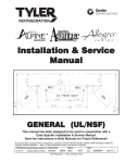
Installation & Service
Manual
TLM, TLD, TLF, TSSD
LIFT FRONT CURVED GLASS MEAT/DELI/FISH MERCHANDISERS
AND SINGLE DECK SELF SERVICE MERCHANDISERS
Medium Temperature Service Display Cases
Save this Instruction Manual for Future Reference!!
This merchandiser conforms to the Commercial Refrigeration Manufacturers Association Health and Sanitation standard CRS-S1-96.
PRINTED IN Specifications subject to REPLACES
IN U.S.A.
change without notice. EDITION
1/99
ISSUE
DATE
7/99
PART
NO.
Tyler Refrigeration Corporation * Cerritos, California 90703
9034862
REV.
B
TLM, TLD, TLF, TSSD
Tyler Refrigeration
CONTENTS
Page
Specifications
TLM/TLD/TLF/TSSD Specification Sheets . . . . . . . . . . . . . . . . . 4-11
Line Sizing Requirements . . . . . . . . . . . . . . . . . . . . . . . . . . . . 12-14
Pre-Installation Responsibilities . . . . . . . . . . . . . . . . . . . . . . . . . . . 15, 16
Installation Procedures
Carpentry Procedures . . . . . . . . . . . . . . . . . . . . . . . . . . . . . . 16-19
Case Line-Up . . . . . . . . . . . . . . . . . . . . . . . . . . . . . . . . . . . . . . . . 17
Lift Front Glass Leveling Instructions . . . . . . . . . . . . . . . . . . . . . . 18
Bumper Installation . . . . . . . . . . . . . . . . . . . . . . . . . . . . . . . . . . . 19
Plumbing Procedures . . . . . . . . . . . . . . . . . . . . . . . . . . . . . . 19, 20
Refrigeration Procedures . . . . . . . . . . . . . . . . . . . . . . . . . . . 20-24
Temperature Control . . . . . . . . . . . . . . . . . . . . . . . . . . . . . . . . . . . 20
Setting the Electronic Thermostat (TLM/TLD/TLF) . . . . . . . . . . 20, 21
Refrigeration System . . . . . . . . . . . . . . . . . . . . . . . . . . . . . . 21, 22
Setting the Superheat . . . . . . . . . . . . . . . . . . . . . . . . . . . . . . 23, 24
Electrical Procedures . . . . . . . . . . . . . . . . . . . . . . . . . . . . . . . . . 25
Electrical Considerations . . . . . . . . . . . . . . . . . . . . . . . . . . . . . . . 25
Defrost Information . . . . . . . . . . . . . . . . . . . . . . . . . . . . . . . . . . . 25
Defrost Control Chart . . . . . . . . . . . . . . . . . . . . . . . . . . . . . . . . . . 25
Installation Procedure Check Lists . . . . . . . . . . . . . . . . . . . 26, 27
Use of Alignment Clamps . . . . . . . . . . . . . . . . . . . . . . . . . . . . . . 27
Wiring Diagrams . . . . . . . . . . . . . . . . . . . . . . . . . . . . . . . . . . . . . . . 27-32
TLM/TLF Case Circuits (8’ & 12’ Cases) . . . . . . . . . . . . . . . . . 28, 29
TLD Case Circuits (8’ & 12’ Cases) . . . . . . . . . . . . . . . . . . . . . 30, 31
TSSD Case Circuits (8’ & 12’ Cases) . . . . . . . . . . . . . . . . . . . . . . 32
Cleaning Instructions
Stainless Steel Cleaning Methods . . . . . . . . . . . . . . . . . . . . . 33, 34
General Cleaning Information . . . . . . . . . . . . . . . . . . . . . . . . . . . 35
Case Cleaning . . . . . . . . . . . . . . . . . . . . . . . . . . . . . . . . . . . . . . . 36
High Pressure Cleaning . . . . . . . . . . . . . . . . . . . . . . . . . . . . . . . 36
General Information
Rear Sliding Door Removal and Installation . . . . . . . . . . . . . . . . . 37
Scale Shelf Installation . . . . . . . . . . . . . . . . . . . . . . . . . . . . . 37, 38
Page 2
December, 1997
Installation & Service Manual
TLM, TLD, TLF, TSSD
Page
Service Instructions
Preventive Maintenance . . . . . . . . . . . . . . . . . . . . . . . . . . . . . . . 38
Light Servicing . . . . . . . . . . . . . . . . . . . . . . . . . . . . . . . . . . . 38, 39
Ballast and Lighting Locations . . . . . . . . . . . . . . . . . . . . . . . . . . . 38
T-8 Lamp Replacement . . . . . . . . . . . . . . . . . . . . . . . . . . . . . . . . 39
Remote Ballast Replacement . . . . . . . . . . . . . . . . . . . . . . . . . . . 39
Front Glass Anti-Fogging System Service . . . . . . . . . . . . . . . . 40
Air Discharge Anti-Sweat Heater Replacement (TLM/TLF) . . . 41
TLM/TLD Lift-Glass Replacement . . . . . . . . . . . . . . . . . . . . . . . 42
Lift-Glass Gas Piston Replacement . . . . . . . . . . . . . . . . . . . 43, 44
Fan Blade and Motor Replacement . . . . . . . . . . . . . . . . . . . . . . 44
Parts Information
Operational Parts List . . . . . . . . . . . . . . . . . . . . . . . . . . . . . . . . . 45
Cladding and Trim Parts List . . . . . . . . . . . . . . . . . . . . . . . . . 45-51
TYLER Warranty . . . . . . . . . . . . . . . . . . . . . . . . . . . . . . . . . . . Back Cover
The following Medium Temperature Lift Glass Meat, Deli & Seafood Service Merchandiser and
Top Display Single Deck Self Service Merchandiser models are covered in this manual:
MODEL
DESCRIPTION
TLM
6’, 8’ & 12’ LIFT GLASS GRAVITY COIL MEAT SERVICE MERCHANDISER
TLD
6’, 8’ & 12’ LIFT GLASS FORCED AIR DELI SERVICE MERCHANDISER
TLF
6’, 8’ & 12’ LIFT GLASS GRAVITY COIL SEAFOOD SERVICE MERCHANDISER
TSSD
6’, 8’ & 12’ OPEN CHEESE SELF SERVICE MERCHANDISER
December, 1997
Page 3
TLM, TLD, TLF, TSSD
Tyler Refrigeration
SPECIFICATIONS
TLM Lift Front Glass Meat Service Merchandiser Specification Sheets
Page 4
January, 1999
Installation & Service Manual
TLM, TLD, TLF, TSSD
TLM Lift Front Glass Meat Service Merchandiser
January, 1999
Page 5
TLM, TLD, TLF, TSSD
Tyler Refrigeration
TLD Lift Front Glass Deli Service Merchandiser Specification Sheets
Page 6
January, 1999
Installation & Service Manual
TLM, TLD, TLF, TSSD
TLD Lift Front Glass Deli Service Merchandiser
December, 1997
Page 7
TLM, TLD, TLF, TSSD
Tyler Refrigeration
TLF Lift Front Glass Seafood Service Merchandiser Specification Sheets
Page 8
January, 1999
Installation & Service Manual
TLM, TLD, TLF, TSSD
TLF Lift Front Glass Seafood Service Merchandiser
January, 1999
Page 9
TLM, TLD, TLF, TSSD
Tyler Refrigeration
TSSD Open Cheese Self Service Merchandiser Specification Sheets
Page 10
January, 1999
Installation & Service Manual
TLM, TLD, TLF, TSSD
TSSD Open Cheese Self Service Merchandiser
December, 1997
Page 11
TLM, TLD, TLF, TSSD
Line Sizing Requirements
Tyler Refrigeration
Use 50’ Column for Sub Feed Line Size
CAUTION
Low temperature suction lines and all liquid lines must be insulated in all applications where subcooling (NC) is used!
This prevents line damage and possible
product damage caused by freezing.
NOTE
Liquid and suction line lengths over 300
equivalent feet are discouraged by
TYLER. Contact applications engineering for recommendations on applications
exceeding 300 equivalent feet! HORIZONTAL SUCTION LINES SHOULD
SLOPE ½” PER 10’ TOWARD THE COMPRESSOR TO AID IN GOOD OIL
RETURN!
Example Only
Suction Line Sizing
The “Case-to-Case Suction Line Sub-Feed
Branch Line Sizing” chart on each spec sheet
can be used to size the sub-feed branch
lines. When the branch line only serves one
case, use the line size listed under 50 equivalent feet for that case. (Example: service
meat case uses 1/2” line; multi-shelf case
uses 1 3/8” line.) Select each succeeding
step on the basis of the number of linear feet
you are at in that case line-up. The suction
line sizes will change in a long case line-up.
Page 12
Liquid Line Sizing
Most single case installations require 3/8” liquid
lines. To determine liquid line sizing for multi
case line-up, see “Liquid Line Sizing” in “BUFF”
section of “TYLER Specification Guide”.
December, 1997
Installation & Service Manual
TLM, TLD, TLF, TSSD
Header along cases - 7/8”
Line into cases are always 1/2”
Note: Tees point down
Main liquid line must be 5/8” minimum (even with just 1 case)
Gas Defrost Liquid Lines
3’ Max. for gas defrost
Gas defrost liquid lines to the cases should
be branched off the bottom of the header.
This ensures a full column of liquid to the
expansion valve. A branch line from the
header to an individual case should be over
3’ long and must have a 3” expansion loop
incorporated.
-100°F to -40°F = 2.5” per 100 foot run
(ultra low temp)
Do not run suction or liquid lines through
cases that are part of a separate system,
especially if either has gas defrost. If there is
no way to avoid this, insulate the piping for
the portion that runs through the other cases.
30°F to 50°F = 1” per 100 foot run
(high temp)
Temperature variations of refrigeration and
defrost cycles cause piping to expand and
contract. Allowing for this expansion and
contraction will prevent piping failures. The
following are typical expansion rates for copper tubing;
December, 1997
-40°F to 0°F = 2” per 100 foot run
(low temp)
0°F to 30°F = 1.5” per 100 foot run
(medium temp)
Expansion loops are designed to provide a
definite amount of travel. Placing the loop in
the middle of a piping run will allow for maximum pipe expansion with the minimal
amount of stress on the loop. Don’t use 45
degree elbows for loop construction because
they will not allow the lines to flex. Refer to
the charts on the next page for expansion
loop lengths. Suction and liquid lines cannot
be joined together or be allowed to touch.
Pipe hangers must not restrict the expansion
and contraction of piping. Insulation on suction and liquid lines makes the whole system more efficient! Insulate - it pays!
Page 13
TLM, TLD, TLF, TSSD
Expansion Loop Sizing
Chart 1 is to be used for A, B, and C type
expansion loops. Chart 2 gives the total
length of the expansion joint (L) along the
outer surface.
Example: Given a 200’ run of 1 3/8” medium
temp piping; there will be a linear expansion
Tyler Refrigeration
of 3” to compensate for (medium temp 1.5”
per 100’). Pipe diameter has no affect on the
amount of linear expansion but is needed for
determining the size of the expansion loop.
Find the 3” column at the top of Chart 1 and
go down until it crosses the 1 3/8” row. The
X dimension is 24”, 48”, or 72” for A, B, or C
type expansion loop respectively.
Type “C” Loop
Type “A” Loop
Type “B” Loop
Tube
O.D.
‘X’ Length - (in inches) for Linear Expansion of:
Tube
O.D.
‘L’ Developed Length of Expansion Offsets
Page 14
December, 1997
Installation & Service Manual
TLM, TLD, TLF, TSSD
PRE-INSTALLATION RESPONSIBILITIES
Shipping Inspections
Shipping Damage
All equipment should be thoroughly examined for shipping damage before and during
unloading.
This equipment has been carefully inspected
at our factory and the carrier has assumed
responsibility for the safe arrival of our product. If damage is concealed or apparent, a
claim must be made to the carrier.
Corporation from any liability.
Refrigeration piping must be sized as
described within this manual by the installer.
Normal applications require refrigeration piping to be insulated unless otherwise stated.
Refer to “Liquid and Suction Line Sizing
Information” section in this manual for
TYLER’s requirements.
Apparent Loss or Damage
Obvious loss or damage must be noted
immediately on the freight bill or express
receipt and signed by the carrier’s agent. If
this is not done, the carrier may refuse the
claim. The carrier will supply the necessary
claim forms.
Concealed Loss or Damage
When the loss or damage is not apparent
until after the equipment has been uncrated,
a claim for concealed damage must be filed.
Upon discovering the damage, make request
in writing to the carrier for inspection within
15 days and retain all packing. The carrier
will supply the inspection report and required
claim forms.
Application Recommendations
These cases are designed and built to be
used in properly air conditioned stores that
maintain a store temperature at or below 75F
(dry bulb) and a 55% relative humidity. These
cases may not operate satisfactorily at higher
temperature and humidity conditions.
Temperature performance is important for
controlling bacteria growth. The installer is
responsible for following these instructions as
set forth within this Installation and Service
Manual. Any variance will produce poor performance, thus releasing TYLER Refrigeration
December, 1997
TYLER Refrigeration Corporation of Niles,
Michigan is a member of CRMA, Commercial
Refrigerator Manufacturers Association. This
group has published a Health and Sanitation
Standard for Retail Food Store Refrigerators,
CRS-S1-96. TYLER has subscribed to this
standard which outlines various practices and
construction methods that manufacturers follow to assure proper refrigeration of products
displayed or stored in the case and to assure
the user practical cleanability.
The information contained herein is based on
technical data and tests which we believe to
be reliable and is intended for use by persons
having technical skill, at their own discretion
and risk. Since conditions of use are outside
TYLER’s control, we can assume no liability
for results obtained or damages incurred
through the applications of the data presented. SPECIFICATIONS ARE SUBJECT TO
CHANGE WITHOUT NOTICE. Printed in the
U.S.A.
Page 15
TLM, TLD, TLF, TSSD
Tyler Refrigeration
INSTALLATION PROCEDURES
Pre-Installation Check List
All cases containing glass MUST be stored
and installed on level surfaces to avoid possible product damage and/or glass breakage.
1. Check for hidden damage while unloading and unpacking of the case.
2. Check the “shipped loose” parts for any
items; such as shelves, nuts and bolts,
caulking, access doors, etc.
WARNING
The raised front glass projects in front of
the case and could cause personal injury to
workers, operators and/or customers.
• Do not leave lift glass raised and unattended.
• Know where the front edge of the raised
glass is when working near it.
3. Check the equipment - remove the screws
used to hold down the deck pans during
shipping. Remove the pans and check
the following, if applicable:
4. Remove all packing material.
5. Check all flare nut connections for tightness.
6. Check all fan bracket bolts for tightness.
7. Check all electrical plug-in connections
for positive seal.
8. Make sure the expansion valve feeler bulb
is securely attached to the suction line.
9. All field wiring and plumbing MUST conform to national, state, and local codes.
10. Do not remove plugs (from flare nuts) or
caps (from threaded connections) until
the unit is ready for final hook-up. All
coils are pressurized and have a Schrader
Valve access fitting. If pressure has been
lost, check for leaks.
This case is designed so the front glass can be
raised for cleaning and merchandising only. It
is recommended that any cleaning or merchandising be done when the store is closed.
If this is not possible, it should be done at a
time when customer traffic is low.
The raised glass should not be left unattended
and should be lowered whenever leaving the
case.
Page 16
December, 1997
Installation & Service Manual
Carpentry Procedures
Case Line-Up
Before starting the case line-up, review the
store layout floorplans and survey the areas
where case line-ups are going to be installed.
TLM, TLD, TLF, TSSD
NOTE
A foam gasket is factory installed on one
end of the case. This gasket fits into a
groove on the adjoining case when cases
are pulled together. Do not depend on the
foam gasket alone to make a good seal!
WARNING
These cases are very heavy and require
two or more people to move and/or position them. Improper handling of these
cases could result in personal injury.
1. Snap chalk lines where the front and rear
base rails of the case are to be located for
the entire line-up.
NOTE
3. Apply two heavy beads of caulking compound from the Filler Kit to the end of
case at dotted (. . .) and dashed (- - -)
lines. Proper caulking provides good
case refrigeration and sanitation.
Front and rear edges of base rails should
always be used to line-up cases. 6” shims
allow adjoining ends of cases to be
shimmed together.
2. Locate highest point on chalk lines as a
reference for determining the number of
shims to be placed under the case base
rails. Position first case at highest point
on the chalk lines and shim case supports
as required. Check leveling across the
top of the case and on top of the color
band.
CAUTION
If the base of this case is not sitting evenly
on the floor, the case could warp when
loaded and possibly break the lift glass.
December, 1997
4. Push cases tightly together making sure
the pull-ups are aligned.
5. Add shims, as required, under the adjoining case base rails. Check leveling at top
of the case and on top of the color band.
Page 17
TLM, TLD, TLF, TSSD
Tyler Refrigeration
CAUTION
Do not drill or use other holes through the
case end for pull-ups. This may deform
the case end and could cause joint leaks
and/or poor refrigeration.
The case should be leveled across the top
(1), close to the hinge, and on the color band
(2). A 4 foot level is recommended, and both
places should be level! This will enable the
lift glass to fit and work properly.
6. Position pull-up bolts and mounting hardware at pull-up locations (A and B). Do
not tighten any pull-up hardware until all
of it has been installed. Tighten all pull-up
hardware equally starting at point A and
finishing at point B. Do not overtighten.
Lift Front Glass Leveling Instructions
Accurate leveling is critical for the proper
operation of the lift glass on this case.
In some instances, setting the case on an
apparently level floor can cause the lift glass
to fit improperly. If there is any twist in the
body, it could cause the lift glass not to fit or
work properly.
If the lift glass still doesn’t close or line-up
properly, add shims to case corners.
Shimming will ensure proper operation and
alignment of the lift glass.
The handle on the lift glass must rest evenly
on the color band. Proper lift glass sealing is
essential for good product refrigeration.
NOTE
Do not anchor the base to the floor or
enclose the case until the lift glass is fitting properly and working correctly.
The emphasis when leveling this case must
be on making sure the lift glass works and
seals properly.
Page 18
December, 1997
Installation & Service Manual
Bumper Installation
TLM, TLD, TLF, TSSD
Plumbing Procedures
Recommended Drain Practices
CAUTION
A clogged waste outlet blocks refrigeration. This could result in inadequate case
cooling and possible food spoilage.
1. Install bumper retaining track on cladding
with screws, if required, using same alignment as old bumper track.
2. Cut vinyl bumper slightly longer than
overall length of case line-up. Starting at
either end of the case, snap end of
bumper onto the bumper retainer track.
3. Curve the bumper back as illustrated.
This will open the bumper and allow it to
snap onto the retainer track. Working in
one direction, “roll” the bumper onto the
retainer track. Just before reaching the
opposite end, final cut the bumper
(approx. 1/8”) longer than the bumper
retainer. The additional 1/8” length will
allow for normal shrinkage from case
cooling.
The installer is responsible for the proper and
code approved installation of a system which
dispenses condensate waste water through
an air gap into the building’s indirect waste
system.
Waste outlets and drip pipes from refrigerators are not intended for direct connection to
the building plumbing system. All remote
refrigerators equipped with automatic or off
time defrost systems are provided with a
waste outlet. The outlet is located in the lowest level of the compartment to which waste
water will drain.
All TYLER display refrigerators are provided
with a water seal. It may be factory installed
or shipped loose for field installation. If
shipped loose, the installer must follow
TYLER’s installation procedure as outlined
within this manual.
The importance of proper drain connections
cannot be overemphasizes. Complications
resulting from drainage problems can be
avoided by following these good drainage
guidelines.
NOTE
Bumper unevenness may be remedied by
striking with a mallet and straight board
along the length of the installation.
December, 1997
1. The minimum slope of waste pipe should
be 1/4” per foot, or more if possible.
Page 19
TLM, TLD, TLF, TSSD
2. The maximum length of waste pipe
should not exceed 12 feet.
3. Waste pipe is recommended. Never use
small diameter copper tubing for waste
piping.
Tyler Refrigeration
Refrigeration Procedures
Refrigeration system and superheat
instructions can be found later in this section. Service case temperature control
information is listed below.
Temperature Control
The temperature of each case is controlled
with a thermostat and suction line solenoid.
One thermostat and one solenoid are
required for up to three cases.
TLD case uses a conventional mechanical
thermostat.
Typical Service Case with Blower Coil
4. On low temp cases, the trap must be
away from the tee to prevent possible
freezing of the trap.
5. Up to two case drains can utilize one floor
drain. NOTE: Both case drains require
individual water seals.
In addition to the thermostat and suction solenoid, a suction stop EPR valve is required in
the suction line. The EPR valve acts as a low
pressure limit to aid in the overall tempetrature control.
Setting Electronic Thermostat - RANCO
(TLM/TLD/TLF)
1. Remove the four screws and cover from
the electronic thermostat.
6. Never put two case drains with two traps
on the same waste pipe. This can cause
an air trap on one of the case drains.
Page 20
2. Set the heating/cooling jumper blocks to
the “COOL” position.
3. Adjust the differential potentiometer
marked “DIFF” to 10°F (TLM/TLD) or 1°F
(TLF).
December, 1997
Installation & Service Manual
4. Position the setpoint dial, on the front
cover, to 29°F (TLM/TLD) or 34°F (TLF).
5. Check the temperature cycles by suspending a thermometer in the same general area as the thermostat probe. The
temperature should cycle between 19°F
and 29°F (TLM/TLD) or 33°F and 34°F
(TLF).
6. Replace the cover and secure with four
screws.
With the cooling mode selected, the differential is below the setpoint. The relay will energize and the LED indicator will illuminate
when the temperature reaches the setpoint
(29°F or 34°F). When the temperature drops
to the setpoint (29°F or 34°F) minus the differential setting (10° or 1°F), the relay and LED
indicator will de-energize and refrigeration will
stop.
Start the refrigeration system (note that the
LED indicator is illuminated) and allow the
case to cool. This allows the thermostat to
cycle the suction solenoid valve from open to
close.
Refrigeration System
CAUTION
• Protect Schrader valve core and cap
and the expansion valve feeler bulb
from excessive heat by removing them
when necessary. Replace properly
before starting the system.
• Brazing and welding operations should
be kept away from both the metal drain
pan and sealing materials in the drain
area. High temperature exposure in
these areas may cause damage to seals
and/or painted surfaces of the drain
pans.
TLM, TLD, TLF, TSSD
The type of refrigerant used in the case will
be specified on the unit nameplate. A
Schrader valve is provided at the left of each
coil for system testing and charging.
The suction and liquid lines to the evaporator
coils are capped off. This holds the dry nitrogen charge inside the evaporator coils.
When cutting off the caps, use a tubing cutter
to prevent the introduction of copper shavings to the system. See the model specification sheet in the case specific I&S manual for
proper line entry and positioning specifications.
Only use clean, dry, sealed refrigeration
grade copper tubing. Make copper to copper
joints with phos-copper alloy (5% silver) or
equal. Make dissimilar metal joints with solder having 35% silver. To prevent internal
contamination of the line, limit the use of soldering paste or flux to the minimum required.
Flux only the male portion of the connection.
Piping should be purged with dry nitrogen or
carbon dioxide during brazing. This prevents
the formation of copper dioxide and scale
during brazing. Copper dioxide and/or scale
can easily clog the small ports in system
valves and pilot valve.
NOTE
The tubing design pressure is 183 psig for
the lowside and 390 psig for the highside.
Do not exceed these pressures.
Line Entry
Refrigeration lines entry may only require a
single entry for an entire line-up of cases. It
could enter the line-up at one end or branch
both ways from the center. Refrigeration lines
may be run from case to case in areas designated for them. Notches are provided in both
ends for this purpose.
Line sizing should meet the suction and liquid
sizing requirements for that case location in
the line-up. See “Line Sizing” section in this
manual. If the cases are connected to a parallel system, the line size will be specified on
the system printout.
December, 1997
Page 21
TLM, TLD, TLF, TSSD
CAUTION
Do not run tubing through these cases to
another machine if the cases are controlled
by a pressure control. Pressure sensed
from the coldest location could affect the
pressure control in a second system. This
is called cross-controlling and should be
avoided.
A pressure drop in the suction line means a
loss in system capacity. It forces the compressor to operate at a lower suction to maintain
the desired temperature in the evaporator coil.
Pressure drops reduce compressor capacity
and increase system compression ratios causing higher operating costs. To minimize pressure drop, keep the refrigeration line run as
short as possible and the number of fittings to
a minimum.
All suction lines should be insulated to minimize heat absorption and condensation drippage. Seal refrigeration lines where they enter
the case. Sealing is necessary to prevent condensation, air leaks and other problems. Be
sure it is done before leaving the job.
NOTE
It is very important to have a good seal
around the refrigeration lines. This will prevent any water leakage into the bottom of
the case. During the installation process do
not disturb the factory seal between the
drain and case ends. This seal must remain
water tight. The access opening should be
insulated along with all refrigeration lines
exiting the case to prevent condensation
buildup on cold surfaces.
Control Options
The temperature of case line-ups can be controlled by one of the following methods:*
1. Indoor single compressor system not using
a liquid pump down before defrost. The
low pressure control on the compressor
system can be set to cycle the compressor
on and off at specific pressures that correspond to the desired temperature range at
the case.
Page 22
Tyler Refrigeration
2. Indoor single compressor system
needing a more accurate temperature control. A thermostat can be
mounted with its sensing bulb in
the discharge air stream on the
case. The thermostat is used to
cycle the compressor on and off at
specific temperature to maintain the
desired case temperature range.
3. Outdoor single compressor system
using a liquid pump down cycle
before defrost, or other applications
that need a more accurate temperature control. A thermostat can be
mounted with its sensing bulb in
the discharge air stream on the
case. The thermostat is used to
cycle a main liquid line solenoid
valve on and off at specific temperatures to maintain the desired case
temperature range. The liquid line
solenoid valve used for temperature
control should be mounted as
close to the case as possible to
minimize the temperature swing
that may occur after the valve closes.
4. Parallel compressor system, or
other applications needing a more
accurate temperature control. An
evaporator pressure regulator
(EPR) valve is installed between the
case and the compressor. The EPR
valve is set to control the case suction pressure which corresponds to
the desired case temperature. The
EPR valve will hold a relative constant pressure at the case and will
not allow it to go below a set pressure.
*See model specification sheet in
the case specific I&S manual for specific control settings for each case.
December, 1997
Installation & Service Manual
Setting the Superheat
Use the instructions, illustration, and chart
below to determine the superheat.
TLM, TLD, TLF, TSSD
expansion valve by turning in the adjusting screw 1 ½ turns.
NOTE: Rear coil expansion valve should
always be adjusted first.
3. Install pressure gage on the coil output.
Most TYLER cases have a Schrader fitting
for this purpose. Record the pressure
reading.
4. Using the table on the following page,
convert this pressure to a temperature.
NOTE: This illustration shows the general
location of piping and components in a
case with two expansion valves.
1. Make sure all connections to the expansion valve(s) are tight.
2. If a case has more than one expansion
valve, starve the flow to the front coil’s
5. Take a temperature reading from the suction line adjacent to the expansion valve
bulb being tested.
6. Subtract the temperature conversion (step
4) from the suction line temperature (step
5). This is the superheat of the evaporator.
7. If case has more than one expansion
valve, reset front coil expansion valve by
TEMPERATURE-PRESSURE CHART
See next page for adjustment settings for Sporlan and Alco Expansion Valves.
December, 1997
Page 23
TLM, TLD, TLF, TSSD
Balanced Port Expansion Valves used in
TYLER cases are preset by an air pressure
bench test. Some final adjustment may be
necessary due to system designs, pressure
drops, and coil loading. Adjustments should
be made with liquid pressures near design,
and after the case has been loaded and
pulled down to normal temperature requirements. Final adjustments are used to maximize case temperature and efficiency.
There is no magic superheat number. Proper
settings can actually occur from as low as 4
or 5°F up to extremes of 17 or 18°F of superheat. Most settings will fall in the 6 to 12°F
range. A proper method is to find a setting
within the ranges previously mentioned that
provides the most stable bulb temperature.
Sometimes there will be a flat reading with virtually no variation. This usually provides the
lowest discharge air temperature reading.
Proper expansion valve settings cannot be
made in a few minutes. Only turns of ¼ to ½
should be made at one time. Wait 15 minutes to allow the system to settle out. Please
refer to comments below regarding the differences in adjustment between Sporlan and
Alco expansion valves.
CAUTION
Forcing the adjustment beyond the stops
will result in damage to the valve.
NOTE
All of the following changes are approximate and should only be used as a guideline!
Tyler Refrigeration
SPORLAN VALVES:
The number of adjustment turns available
between stops on the Sporlan valves is 9 to
10 turns (in or out).
• With R-22 refrigerant, 1 turn will result in
approximately a 5.5 or 3°F superheat
change for low or medium temperature
applications respectively.
• With R404A refrigerant, 1 turn will result in
approximately a 4.5 or 2.5°F superheat
change for low or medium temperature
applications respectively.
• With R-502 refrigerant, 1 turn will result in
approximately a 5 or 2.5°F superheat
change for low or medium temperature
applications respectively.
• With R-507 refrigerant, 1 turn will result in
approximately a 4.5 or 2.5°F superheat
change for low or medium temperature
applications respectively.
ALCO VALVES:
The number of adjustment turns available
between stops on the Alco valves is 10 to 12
turns (in or out).
• With R-22 refrigerant, 1 turn will result in
approximately a 4.5 or 2°F superheat
change for low or medium temperature
applications respectively.
• With R404A refrigerant, 1 turn will result in
approximately a 3.5 or 1.5°F superheat
change for low or medium temperature
applications respectively.
• With R-502 refrigerant, 1 turn will result in
approximately a 3.5 or 1.5°F superheat
change for low or medium temperature
applications respectively.
• With R-507 refrigerant, 1 turn will result in
approximately a 3.5 or 1.5°F superheat
change for low or medium temperature
applications respectively.
Page 24
December, 1997
Installation & Service Manual
Electrical Procedures
time control stops the refrigerant and
allows the case to defrost at the proper
time and duration each day.
Electrical Considerations
CAUTION
Make sure all electrical connections at components and terminal blocks are tight. This
prevents burning of electrical terminals
and/or premature component failure.
NOTE
The ballast box is located behind the front
kickplate. It houses ballasts and terminal
blocks.
Case Fan Circuit
This circuit is to be supplied by an uninterrupted, protected 120V circuit. The case fan circuit
is not cycled on this case.
Fluorescent Lamp Circuit
TL case lighting is supplied by T-8 electronic
ballast lights. It is controlled by a light switch
in each case. The standard lighting is 1-row of
horizontal canopy lights.
Anti-Sweat Circuit
All anti-sweat heaters are wired directly to the
main power supply so they can operate at all
times.
Defrost Information
Defrost Control Chart
TLM/TLD/TLF Defrost Option Settings
Defrost
Defrost Defrosts Duration
Per Day
(Min)
Type
Off Time
2
60
Term.
Temp.
-----
TSSD Defrost Option Settings
Defrost
Defrost Defrosts Duration
Type
Per Day
(Min)
Off Time
2
60
Term.
Temp.
-----
Off Time Defrost
All cases that use a refrigerated coil that operates below the freezing point of water will collect frost during the refrigeration cycle. Too
much frost build-up on the cooling coil stops
the effective air flow and refrigeration. An off
December, 1997
TLM, TLD, TLF, TSSD
The refrigeration is stopped with a time
clock (mechanical or electronic) by either
turning off the compressor directly, or closing a liquid line solenoid or suction isolation valve (ex. suction line solenoid or suction stop EPR valve). The time clock is set
for the proper number of defrosts per day
and the proper duration per defrost based
on the information provided under
“Specifications” in the case specific manual. The time clock may be an individual
clock on single compressor system; a
multi-circuit clock on parallel compressor
system; or an electronic clock on either
compressor system.
Single Condensing Unit
Liquid flow may be interrupted by a normally closed liquid line solenoid valve
(installed at the compressor or case) controlled by a thermostat and wired to the
time clock. The time clock would cause
the solenoid to close, this would in turn
shut off the flow of liquid refrigerant to the
system(s). The compressor would continue to run and pump down the system(s).
The condensing unit would soon shut off
on low pressure. The time clock may also
be wired directly to the compressor contactor.
Parallel Compressor Unit
For cases operated from a parallel compressor rack, an evaporator pressure regulator (EPR) valve may be factory installed
on the suction stub of the parallel compressor rack. The EPR valve will work in
conjunction with the defrost circuit(s). This
is temperature regulation (by pressure) of
the entire lineup. A solenoid may be used
in conjunction with the EPR valve to stop
refrigerant flow during defrost.
Page 25
TLM, TLD, TLF, TSSD
Tyler Refrigeration
Installation Procedure Check Lists
Plumbing Check List
Carpentry (Line-Up) Check List
1. All plumbing must conform to all national,
state and local codes.
NOTE
NOTE
All necessary hardware and caulking can
be found in the Filler Kit located in the well
of each case.
Be sure the drain is installed in accordance with the following specifications and
the drain instructions in this manual.
1. Check the level of the floor area where the
cases are going to be lined up.
2. The minimum slope should be ¼” per foot
or more if possible.
2. Set and level the first case at the highest
point on the floor.
NOTE
Adjacent cases may require different
amounts of shimming to allow for proper
case line-up.
3. Level cases as necessary to align case
pull-ups, fronts, tops, and allow for proper operation.
4. Have case to case joints been properly
caulked and sealed? Each joint requires
two beads of caulking where the cases
join together. One bead on the inside and
outside of the foam gasket and door
frame assures good sanitation and refrigeration. See “Case Line-Up” in this manual for proper caulking locations.
5. Have the patch ends been properly
caulked and installed with the proper
hardware?
6. For cases with shelves, make sure the
shelving bracket slots on multi-shelf cases
line-up and that the shelves are installed
in the proper position.
NOTE
The bumpers should all be pushed tight
against the center case in the line-up and
secured with the end tensioners before the
end trims are installed.
7. After cases are completely installed, make
sure all bumpers, front cladding, raceway
covers and kickplates are properly
installed and secured.
Page 26
3. The maximum length should not exceed
12 feet.
4. Never downsize the drain lines. Lines
should be at least the same diameter as
the trap.
CAUTION
Hooking two cases and traps into the
same drain line will cause an air trap in
one of the two cases. This will cause
improper drainage to the case with the air
trap.
5. Two cases can utilize one floor drain as
long as both lines and traps are run separately to that drian.
Electrical Check List
1. All field wiring must conform to national,
state and local codes.
2. Make sure all electrical connections are
properly connected and tight.
Refrigeration Check List
In addition to the standard practices which
should be used in the installation of this case,
the installer should pay particular attention to
the following items:
1. Has the refrigerant line entry been
caulked thoroughly?
2. Are all fans running? Are the fan electrical
connections tight?
NOTE
Proper settings and/or temperatures for
items 3, 4 and 5 can be found in the
“Model Specification Sheets” in the case
specific I&S manual or the “BUFF” section
in the Specification Guide.
December, 1997
Installation & Service Manual
TLM, TLD, TLF, TSSD
3. Is the defrost control set for correct number of defrosts per day?
4. Is the failsafe set for the proper times?
NOTE
5. Does the discharge air temperature match
the recommended temperature for this
case?
Individual case
alignment clamps
are available
through TYLER
Service Parts
Department
under Part No.
5092494.
6. Is the suction pressure drop less than 2
PSIG from the last case to the compressor? (Remote case only)
7. Are the expansion valve feeler bulbs
securely attached to the suction lines?
8. After final hook-up of the case, let it run
through a defrost cycle (preferably two or
more). Check the duration and frequency
of the defrost cycle for compliance to
specification data.
9. Check the operating temperature to be
sure the case is functioning within the recommended guidelines.
10. Verify that the store temperature and
humidity levels are within the recommended guidelines. Use a wet and dry bulb
psychrometer to check the store temperature. Check for outside influences that
might affect the case performance.
(Example: Drafts from ventilator openings
or radiant heat from light fixtures that are
too close.)
Use of Case Alignment Clamps
1. Check and mark the floor where the cases
are to be set.
2. Set the first case in the line-up on the
highest point of the floor.
3. Level the first case end-to-end and frontto-back using the provided shims.
NOTE
6” shims should be placed beyond the end
of the base rails so the next case can be
set on the same shims.
December, 1997
4. Set the next case in the line-up. Use two
alignment clamps on the horizontal joint
in the bottom of the cases. The clamp
near the front of the cases will line-up the
hand rails. The clamp near the back of
the cases will line-up the shelving bracket
slots.
5. Level and shim the case end-to-end and
front-to-back.
6. Adjust the alignment clamps as needed to
allow for the installation of pull-up hardware.
NOTE
Do not remove alignment clamps until the
pull-up hardware has been tightened.
WIRING DIAGRAMS
ELECTRICIAN NOTE - OVERCURRENT
PROTECTION
120V circuits should be protected by 15 or 20 Amp
devices per the requirements noted on the cabinet
nameplate or the National Electrical Code, Canadian
Electrical Code - Part 1, Section 28. 208V defrost
circuits employ No. 12 AWG field wire leads for field
connections. On remote cases intended for end to
end line-ups, bonding for ground may rely upon the
pull-up bolts.
The following pages show wiring diagrams for
case and lighting circuits
Page 27
TLM/TLF Case Circuits (8’ Cases)
Page 28
December, 1997
TLM/TLF Case Circuits (12’ Cases)
December, 1997
Page 29
TLD Case Circuits (8’ Cases)
Page 30
December, 1997
TLD Case Circuits (12’ Cases)
December, 1997
Page 31
TSSD Case Circuits (8’ and 12’ Cases)
Page 32
December, 1997
Installation & Service Manual
TLM, TLD, TLF, TSSD
CLEANING INSTRUCTIONS
WARNING
TYLER Refrigeration does not recommend
the use of high pressure cleaning equipment on service style cases!! The sealing
of front glass and end joints is critical in
these cases and high pressure cleaners
can penetrate and/or damage these seals.
Damaged seals allow water leaks and/or
air leaks that can cause poor case refrigeration.
CAUTION
• When cleaning this case, try not to introduce water into the case faster than it
can be carried away by the waste outlet.
• Always use a soft cloth or sponge with
mild detergent and water to clean the
front glass. Never use abrasives or
scouring pads to clean glass. They can
scratch and/or damage the glass.
Stainless Steel Cleaning Methods
The cleaning data in the following stainless steel cleaning chart was supplied by AISI. The information was supplied by
Prime Metals Division, Alumax Aluminum Corporation.
TYPE OF CLEANING
CLEANING AGENT*
APPLICATION METHOD**
EFFECT ON FINISH
Routine cleaning
Soap, ammonia or detergent and water.
Sponge with cloth, then
rinse with clear water and
wipe dry.
Satisfactory for use on all
finishes.
Smears and fingerprints
Arcal 20, Lac-O-Nu, Lumin
Wash O’Cedar Cream
Polish, Stainless Shine
Rub with cloth as directed
on the package.
Satisfactory for use on all
finishes. Provides barrier film
Apply with damp sponge or
cloth.
Satisfactory for use on all
finishes.
Rub with damp cloth.
Satisfactory for use on all
finishes if rubbing is light.
Grade FFF Italian pumice,
whiting or talc
Rub with damp cloth.
Use in direction of polish lines
on No. 4 (polished) finish.
May scratch No. 2 (mill) and
No. 7 and 8 (polished) finishes.
Liquid NuSteel
Rub with dry cloth. Use a
small amount of cleaner.
Use in direction of polish lines
on No. 4 (polished) finish.
May scratch No. 2 (mill) and
No. 7 and 8 (polished) finishes.
Paste NuSteel or DuBois
Temp
Rub with dry cloth. Use a
small amount of cleaner.
Use in direction of polish lines
on No. 4 (polished) finish.
May scratch No. 2 (mill) and
No. 7 and 8 (polished) finishes.
Cooper’s Stainless Steel
Cleaner, Revere Stainless
Steel Cleaner
Apply with damp sponge or.
cloth.
Use in direction of polish lines
on No. 4 (polished) finish.
May scratch No. 2 (mill) and
No. 7 and 8 (polished) finishes.
Household cleaners (Old
Dutch, Lighthouse, Sunbrite,
Wyandotte, Bab-O, Gold Dust,
Sapolio, Bon Ami, Ajax or
Comet)
Rub with a damp cloth. May
contain chlorine bleaches.
Rinse thoroughly after use, if
left on surface, may lead to
corrosion.
Use in direction of polish lines
on No. 4 (polished) finish.
May scratch No. 2 (mill) and
No. 7 and 8 (polished) finishes.
Stubborn spots and
Allchem Concentrated
stains, baked-on
Cleaner
splatter, and other light
discolorations
Samae, Twinkle, or Cameo
Copper Cleaner
July 1999
Page 33
TLM, TLD, TLF, TSSD
TYPE OF CLEANING
CLEANING AGENT*
Tyler Refrigeration
APPLICATION METHOD**
EFFECT ON FINISH
Grade F Italian pumice, Steel Rub with a damp cloth.
Bright, Lumin Cleaner, Zud,
Restoro, Bon Ami, Ajax or
Comet
Use in direction of polish lines
on No. 4 (polished) finish.
May scratch No. 2 (mill) and
No. 7 and 8 (polished) finishes.
Penny-Brite or Copper-Brite
Rub with a dry cloth. Use a
small amount of cleaner.
Use in direction of polish lines
on No. 4 (polished) finish.
May scratch No. 2 (mill) and
No. 7 and 8 (polished) finishes.
Penny-Brite or Copper-Brite
Rub with a dry cloth.
Use in direction of polish lines
on No. 4 (polished) finish.
May scratch No. 2 (mill) and
No. 7 and 8 (polished) finishes.
Paste NuSteel or DuBois
Temp
Rub with dry cloth. Use a
small amount of cleaner.
Use in direction of polish lines
on No. 4 (polished) finish.
May scratch No. 2 (mill) and
No. 7 and 8 (polished) finishes.
Revere Stainless Steel
Cleaner
Apply with a damp sponge
or cloth.
Use in direction of polish lines
on No. 4 (polished) finish.
May scratch No. 2 (mill) and
No. 7 and 8 (polished) finishes.
Allen Polish, Steel Bright,
Wyandotte, Bab-O or Zud
Rub with a damp cloth.
Use in direction of polish lines
on No. 4 (polished) finish.
May scratch No. 2 (mill) and
No. 7 and 8 (polished) finishes.
Burnt-on foods and
grease, fatty acids,
milkstone (where swabbing or rubbing is not
practical)
Easy-Off, De-Grease-It, 4-6%
hot solution of such agents
as trisodium tripolyphospate,
or 5-15% caustic soda
solution
Apply generous coating.
Allow to stand for 10-15 min.
Repeated application may
be necessary.
Excellent removal, satisfactory
for use on all finishes.
Tenacious deposits,
rusty discolorations,
industrial atmospheric
stains
Oakite No. 33, Dilac, Texo 12,
Texo N.Y., Flash-Klenz,
Caddy Cleaner, Turco Scale
4368 or Permag 57.
Swab and soak with clean
cloth. Let stand 15 minutes
or more according to directions on package. Rinse
and dry.
Satisfactory for use on all
finishes.
Hard water spots
and scale
Vinegar
Swab or wipe with a cloth.
Rinse with water and dry.
Satisfactory for use on all
finishes.
5% oxalic acid, 5% sulamic
acid, 5-10% phospheric acid,
or Dilac, Oakite No. 33,
Texo 12 or Texo N.Y.
Swab or soak with a cloth.
Let stand 10-15 minutes.
Always follow with neutralizer
rinse, and dry.
Satisfactory for use on all
finshes. Effective on tenacious
deposites or where scale has
built up.
Organic solvents such as
carbon tetrachloride, trichlorethylene, acetone, kerosene, gasoline, benzene,
alcohol and chlorethane n.u.
Rub with a cloth. Organic
solvents may be flammable
and/or toxic. Observe all
precautions against fire.
Do not smoke while vapors
are present. Be sure area
is well ventilated.
Satisfactory for use on all
finishes.
Heat tint or heavy
discoloration
Grease and oil
*
Use of proprietary names is intended only to indicate a type of cleaner, and does not constitute an endorsement, nor is
omission of any proprietary cleanser to imply its inadequacy. It should be emphasized that all products should be used in
strict accordance with instructions on package.
**
In all applications a stainless steel wool or sponge or fibrous brush or pad are recommended. Avoid use of ordinary steel
wool or steel brushes for scouring stainless steel.
Page 34
December, 1997
Installation & Service Manual
General Cleaning Information
Equipment life and performance are directly
related to good cleaning and sanitation practices. Recommended cleaning intervals will
vary depending on the case’s useage.
Cleaning cases and case parts regularly will
keep high sanitation levels, increase case life,
and minimize maintenance costs.
All TYLER cases provide the following case
cleaning features to support good cleaning
and sanitation practices.
• Removable front ducts and lower trays
• Fully accessible 1” or 2” waste outlets on
most cases
• Hinged or easily removable fan panels
provide access to lower coil and drain pan.
• Seamless, smooth drain pan is water-proof
and contoured for easy cleaning and rapid
drainage.
Since cases are made up of different types of
materials, the care requirements change with
the material type and style.
CAUTION
• Never use abrasive scouring pads or
cleansers on exterior or interior surfaces. The abrasive materials could
scratch the surfaces.
• Do not use any ammonia based cleaning products on any cases with electronic and solid state components. The
ammonia will permanently damage
these components.
Exterior metal surfaces are painted with high
quality baked-on polyester base refrigerator
enamel. This material should be cleaned
daily with a damp cloth. After initial installation, apply coat of appliance wax these surfaces. Repeat wax application as necessary
to keep surfaces shining.
Textured rigid vinyl surfaces (bumpers,
handrails, raceways & kickplates) should be
cleaned with a soft cloth and warm soapy
water, or with non-abrasive cleaners like
Fantastik or Pro Formula 409 with a mildly
abrasive sponge. Both of these cleaners will
December, 1997
TLM, TLD, TLF, TSSD
do an excellent job in most instances. Clean
difficult spots with Comet cleanser with chlorinal and a plastic scrubber or abrasive
sponge. Manufacturers directions should be
followed carefully.
CAUTION
Do not use Comet on corner or vacuum
formed trim. Discoloration could occur.
Nylon corner trim for island cases and vacuum formed trim for wedge cases should be
cleaned only with Fantastik or Pro Formula
409.
Cleaned surfaces treated with Armour All or
Pledge furniture polish will help keep surfaces
looking good and make them easier to clean.
WARNING
Do not use hot water on cold glass surfaces. This can cause the glass to shatter
and could result in personal injury. Allow
glass fronts, ends and service doors to
warm before applying hot water.
Exterior and interior glass surfaces, brushed
aluminum and chrome should be cleaned
with a lint-free cloth and warm water or glass
cleaner.
Remove normal accumulation of dirt and
debri daily to maintain efficient refrigeration.
Interior surfaces require different cleaning
intervals. Meat and produce cases should be
cleaned at least once a week; dairy cases
every two to four weeks; and frozen food
cases every two to six months. Interior surfaces may be cleaned with most domestic
detergents and sanitizing solutions with no
harm to the surfaces.
Honeycombs or grids in the air ducts should
be checked and cleaned whenever the case
interior is cleaned. To clean a honeycomb or
grid, remove the screws, retainer and honeycomb or grid from the air ducts. Clean the
honeycomb or grid with compressed air, vacuuming system, or spray detergent and rinse.
Make sure the honeycomb or grid is dry
before replacing it in the case. Reinstall honeycomb or grid in air duct and secure with
retainer and screws.
Page 35
TLM, TLD, TLF, TSSD
Case Cleaning
All case cleaning is dependent on proper
installation of the cases with good caulking
between cases and adequate case drainage
system.
NOTE
Consult a service agency for proper
method of shutting off the refrigeration and
electrical supply.
1. Shut off refrigeration supply to the case(s)
and electrical power to the case fans, antisweat wires and internal lights.
2. Remove product from case and store in
an another case or walk-in facility.
3. Remove screens, trays, bottom pans and
ducts where applicable. Clean parts separately as discribed on this page.
CAUTION
Do not soak lighted shelves! Water will
short or damage to the shelf lighting system.
4. If case has lighted shelves, remove and
clean separately by wiping with a damp
cloth. Make sure receptacle covers are
installed when shelves are removed.
5. Remove all loose debris from the case. It
could clog the drain during cleaning.
NOTE
• If a germicidal detergent is not available, rinsed after cleaning with detergent and apply a sanitizer. Rinse the
sanitizer thoroughly and let air dry.
• When cleaning and rinsing this case, try
not to use water faster then the case
drain can carry it away.
6. Clean surface with warm water and germicidal detergent at recommended concentration. A brush or cleaner pad will aid in
removing dirt. Don’t soak electrical wiring
and fans unnecessarily. Rinse thoroughly
with clean water and let air dry.
Page 36
Tyler Refrigeration
7. Replace all internal parts so that they seat
properly. This is necessary for proper
case operation.
WARNING
Never turn case electrical power on until
all components are dry! Reconnecting
power to case with wet components could
cause damage the case or personal injury.
8. Restart refrigeration supply to the case(s)
and electrical power to the case electrical
circuits.
9. Replace product after the case has
reached the proper operating temperature.
High Pressure Cleaning
If a high pressure cleaner is used for case
cleaning, the following cleaning precautions
must be taken.
WARNING
Wear safety goggles while using high pressure equipment. This equipment is
designed to operate at 500 psi pressure.
High pressure water and/or flying objects
could cause eye or other bodily injuries.
• Remove all loose and removable electrical components before using high pressure equipment.
• Do not use water over 160°F. Water too
hot will cook soil into place and obscure
the worker’s visability.
• Do not misuse high pressure spray
equipment by directing spray on any
electrical equipment such as fan motors
and light sockets.
• Do not direct high pressure spray at
case joints or glass joints. The seals
may not hold up to the high pressure.
December, 1997
Installation & Service Manual
TLM, TLD, TLF, TSSD
GENERAL INFORMATION
(TLM Cases)
Rear Sliding Door Removal and
Installation (TLD Cases)
The TLM sliding doors and door frame
assembly are removable as one unit for
cleaning and to aid in case maintenance.
The TLD sliding doors are individually removable for cleaning and to aid in case maintenance. NOTE: DO NOT FULLY IMMERSE
DOORS WHEN CLEANING. The inner and
outer doors are marked with labels from the
factory. If the doors are not labeled, the inner
1. Make sure doors are closed in the door
frame. With both hands, lift up bottom
door frame until it clears the bottom corner supports.
door can be identified as having the limiter
stops on it.
1. Open the outer door about an inch from
the door frame. Firmly grasp both sides
of the outer door and lift into the upper
track until it clears the lower track.
2. Tilt out the bottom of the outer door so it
can clear the lower track. Lower the outer
door out of the upper track to remove it
from the case.
3. Repeat steps 1 and 2 to remove the inner
door.
4. Reverse the above steps to replace the
rear sliding doors.
2. Tilt out the bottom of the door frame to
clear the bottom corner supports. Firmly
grasp the door frame and lift to remove it
from the case.
3. Reverse the above steps to replace the
rear sliding door assembly.
Scale Shelf Installation
(TLD Cases)
The TLD optional scale shelf is mounted to a
center mullion on the back of the case. The
shelf rests on the flat portion of the top of the
case. Use the follow instructions to mount
the scale shelf assembly.
1. Remove the four screws and the shelf
platform from the shelf bracket.
2. Position the shelf bracket on a rear mullion with the top of the bracket level with
the top of the case. Drill pilot holes in the
center mullion and secure the shelf bracket to the mullion with two screws.
3. Reinstall shelf platform to shelf bracket
with four screws.
July, 1999
Page 37
TLM, TLD, TLF, TSSD
(TLM Cases)
The TLM optional scale shelf assembly
mounts on top of the shelf on the back of the
case.
Tyler Refrigeration
3. Make it a policy to perform routine inspections of the electrical connections. Check
them for loose connections and/or frayed
wires. Make sure the lamp guards are
installed correctly. Serious problems can
be avoided by taking care of small problems when they are found.
4. Keep the drains clean and free of debris.
Clogged drains rob the case of needed
refrigeration.
5. Do not use ammonia or ammonia based
cleaners on or around electronic or
solid-state components. The ammonia
will damage these components.
1. Position shelf assembly over the back
shelf in front of a center upright.
2. Drill pilot holes in the bottom of the back
shelf and secure the shelf assembly
bracket to the back shelf with two screws.
SERVICE INSTRUCTIONS
Preventive Maintenance
1. Set up a routine cleaning program, as
outlined in this manual. Make sure
employees are aware of the need for
proper case cleaning and follow the recommended guidelines.
WARNING
Always shut off electricity to case before
cleaning and/or inspecting electrical components and/or connections. Moisture on
electrical components could cause electrical shock and/or personal injury.
2. When cleaning this case, don’t overlook
such things as the fan blades and coils.
Be sure to keep fan blades and exposed
coils free of dirt and dust. Accumulated
dirt on fan blades could lead to premature
fan motor failure.
Page 38
6. Periodically inspect the insulation around
the suction lines. Repair or replace any
loose or missing insulation. These lines
must be insulated at all times.
7. Make sure the case is loaded correctly. Do
not use large signage in a case. Do not let
the product block or cover the air ducts, or
extend above the “load lines”. Keep the
product stored or stacked neatly.
8. Check the enviroment around the case.
Misdirected air drafts from fans, open windows, or doors can adversely affect the
case performance. Extra lighting can also
affect the case temperature.
Light Servicing
Ballast and Lighting Locations
All light ballasts are remotely mounted in an
electric box behind the front kickplate.
In order to retain safety approval with
Underwriter’s Laboratory and the Canadian
Standards Association, the mounting of electrical components and interconnecting wires
must not deviate from the following instructions. Only qualified personnel are authorized
to install the accessory items. TYLER
Refrigeration recommends you order all components from its Service Parts Department.
December, 1997
Installation & Service Manual
T-8 Lamp Replacement
WARNING
Shut off light switch or disconnect power
supply before changing a lamp. 600V
lighting system and/or ballast surges can
burn out adjacent lamps and/or cause personal injury or death.
NOTE
Unplugging a shelf lamp will shut off all
the shelf lamps in that case section.
Installing the receptacle cover in place of
the lamp plug will complete the circuit and
turn on the rest of the shelf lamps in that
case section.
TLM, TLD, TLF, TSSD
5. Lamp must be installed with end pins in a
vertical orientation. Slide pins on both
ends of lamp into slots in the lamp holders as far as possible. Rotate lamp 1/4
turn to lock into the lamp holders.
6. Turn on the light switch or reconect the
power to the lights.
Remote Ballast Replacement
WARNING
Shut off or disconnect power supply to
case before changing a ballast. 600V electrical power from wire ends could damage
other components and/or cause personal
injury or death.
1. Remove kickplate from rear of case.
NOTE
If tappit screws are not available, a starwasher should be used between the ballast and the heads of the screws.
1. Grasp burned out lamp and shield firmly
with the fingers of both hands. Rotate 1/4
turn either direction.
2. Lower lamp downward and remove from
case.
2. Install required number of ballasts (2) in
electric box (1) with two screws (3) each.
3. Remove lamp from shield by pulling off
either end cap. Slide lamp out of shield.
3. Identify and connect required wiring harnesses (upper, lower, etc...) to the ballast
connectors (4).
4. Replace cover on electric box (1).
4. Slide new lamp into shield and replace
end cap.
December, 1997
Page 39
TLM, TLD, TLF, TSSD
Front Glass Anti-Fogging System
Service
TLM, TLD and TLF cases have a front glass
anti-fogging fan and a front glass anti-sweat
heater. Use the following instructions to
replace the anti-sweat heater and/or the antifogging fan.
WARNING
Shut off or disconnect power supply to
case before replacing any part of the antifogging system. Electrical power from
wire ends could damage other components and/or cause personal injury or
death.
Tyler Refrigeration
5. Note position of old heater wire and foil
tape. Remove foil tape and heater wire.
Install new heater wire and foil tape in
same position as removed.
6. Plug-in the new heater wire at the harness
connector.
7. Reinstall front cladding and bumper components.
Front Glass Anti-Fog Fan Replacement
Front Glass Anti-Sweat Replacement
1. Lift and tlit out the lower front cladding to
remove from front of case.
2. Lift and remove kickplate from front of
case.
1. Lift and tlit out the lower front cladding to
remove from front of case.
2. Remove vinyl cart bumper, screws and
retainer from upper front of case. Keep all
screws.
3. Remove upper front cladding and insert
from front of case. Keep all screws.
4. Disconnect anti-sweat heater wire by
unplugging it at the harness connector.
Page 40
3. Remove four screws from fan panel. Tilt
panel forward at top edge and lift to
remove fan panel from case.
4. Disconnect defogger fan power cord.
Remove four screws and defective fan.
5. Install new defogger fan with four screws
and reconnect the power cord.
6. Reinstall fan panel in front of case and
secure with four screws.
7. Reinstall kickplate and lower front cladding.
December, 1997
Installation & Service Manual
TLM, TLD, TLF, TSSD
Air Discharge Anti-Sweat Heater
Replacement
TLM, TLF and TSSD cases have an antisweat heater above the air discharge duct.
Use the following instructions to replace the
air discharge anti-sweat heater.
WARNING
Shut off or disconnect power supply to
case before replacing a heater. Electrical
power from wire ends could damage other
components and/or cause personal injury
or death.
1. Remove screws and lower the anti-sweat
heater cover to access the heater wire.
2. Disconnect the heater wire from the harness at the connector. Remove the heater
cover and wire from the case.
3. Note position of old heater wire and foil
tape on the heater cover. Remove foil
tape and heater wire. Install new heater
wire and foil tape in same position as
removed.
4. Plug-in the new heater wire at the harness
connector.
5. Reinstall heater cover and heater assembly with screws.
December, 1997
Page 41
TLM, TLD, TLF, TSSD
Tyler Refrigeration
TLM/TLD Lift-Glass Replacement
WARNING
Wear safety glasses and gloves and use at
least two people when replacing glass.
Glass is heavy and weight distribution is
uneven. Mishandling of glass could cause
breakage and/or personal injury.
If replacing unbroken glass:
1. Raise the old glass to the full UP position.
NOTE
Glass weighs approximately 70 lbs and
requires assistance for properly support.
2. With assistants firmly holding both ends
of the glass, loosen the set screws on the
underside of the glass clamp with 3mm
hex key wrench. Remove old glass from
glass clamps.
NOTE
Note positioning and installation of vinyl
edge channel, aluminum and hand grip
before removing.
3. Remove vinyl edge channel and aluminum from old glass (if possible).
Remove the aluminum hand grip from old
glass. Install vinyl edge channel, aluminum and hand grip on new glass in
same positions and manner as removed.
NOTE
Glass must be fully inserted into glass
clamp before tightening.
4. With aid of assistants, lift and position
new glass into glass clamp. Tentatively
position glass in glass clamp and tighten
set screws. Do not overtighten.
5. Slowly lower glass to check position. If
adjustment is necessary, raise glass and
have assistants hold both ends. Loosen
set screws, adjust the glass position and
retighten set screws. Tighten each set
screw to 0,8 Nm of torque. Do not overtighten.
If replacing broken glass:
1. The glass clamp is probably already in
the full UP position. Loosen set screws
that hold glass and carefully remove broken glass pieces. The use of a pencil
point and/or needle nose pliers helps in
the removal of broken glass pieces from
the glass clamp.
2. Follow steps 3 thru 5 in “If replacing
unbroken glass:” to install new glass.
Page 42
December, 1997
Installation & Service Manual
Lift-Glass Gas Piston Replacement
WARNING
TLM, TLD, TLF, TSSD
• Do not attempt to perform any work on
case while piston is in compressed
state.
The TL series cases rely upon gas pistons
to assist lifting the glass and holding it in
the raised position. The glass is heavy
and difficult for one person to lift alone
while replacing a gas piston. Use an
assistant to prevent possible glass breakage and/or personal injury.
• Raise glass to full UP position before
beginning any work involving gas pistons.
Since gas pistons are very powerful when
in compressed state, follow these cautions
during replacement:
• Dispose of gas piston as soon as possible after removal.
• Do not attempt to alter a gas piston in
any way.
• Do not expose a gas piston to excessive
heat.
TLM Gas Piston Replacement:
1. Have an assitant lift and hold the glass in
the full UP position. Note position and
relationship of glass lift components.
2. With 13mm wrench, loosen locknut. Use
4mm hex key wrench to remove screw
from pivot.
3. Grasp top of piston and pull upward to
remove it from strut. Note weight capacity
printed on side of piston, example:
0500N (500 Newton). Replacement piston should be of same weight capacity as
the piston being replaced.
4. With 2mm hex key wrench, loosen set
screw from piston end adapter (approx. 2
turns). Remove pin and end adapter from
end of piston.
December, 1997
5. Install end adapter and pin on end of new
piston and secure with set screw. Insert
piston into strut until end of piston
engages the stop pin. Refer to drawing
for correct orientation of piston end
adapter relative to pivot.
6. Reinstall screw into pivot until it bottoms
out at end of threaded hole in pivit. Back
screw off 1/4 turn. While graping screw to
prevent turning, install nut and star washer onto screw. Using 13mm wrench and
4mm hex key wrench, tighten locknut to
secure screw. Do not allow screw to
tighten against pivot pin.
7. Lower and raise glass several times to
check operation.
Page 43
TLM, TLD, TLF, TSSD
TLD Gas Piston Replacement:
Tyler Refrigeration
Fan Blade and Motor Replacement
WARNING
Shut off or disconnect power supply to case
before servicing a fan. Automatic cycling of
fan or electrical power to wire ends could
cause personal injury and/or death.
Fan Blade Replacement
1. Have an assitant lift and hold the glass in
the full UP position. Note position and
relationship of glass lift components.
2. With 2mm wrench, loosen set screw on
piston end. Remove pin from piston end
and lift cam joint.
3. Grasp end of piston and pull outward to
remove it from strut. Note weight capacity
printed on side of piston, example:
0500N (500 Newton). Replacement piston should be of same weight capacity as
the piston being replaced.
4. Slide new piston into strut until it engages
the stop pin.
5. Install pin into lift cam joint and piston
end. Secure pin with set screw.
6. Lower and raise glass several times to
check operation.
1. Remove bottom tray(s) (1) from case (2).
2. To replace fan blade (3), remove spring clip
(4) and fan blade (3) from fan motor shaft
(5). Discard spring clip.
3. Install new fan blade (3) on fan motor shaft
(5) and secure with new spring clip (4).
4. Replace bottom tray(s) (1) in case (2).
Fan Motor Replacement
1. Remove bottom tray(s) (1) from case (2).
2. Remove three screws and mounting brackets (6) and fan plenum (7).
3. Carefully lift fan motor assembly and unplug
wire connector.
4. Remove three screws and mounting brackets (6) from fan motor (5).
NOTE
If replacement blades and/or motor are not
available, unplug motor and cover opening
until the replacement parts are available.
5. Replace new fan motor assembly in reverse
order.
Page 44
December, 1997
Installation & Service Manual
TLM, TLD, TLF, TSSD
PARTS INFORMATION
TLM, TLD, TLF, TSSD Operational Parts List
Case Model
Electrical Circuit
Case Size
TLM
TLD
TLF
115 Volt 60 Hertz
115 Volt 60 Hertz
115 Volt 60 Hertz
8’
12’
8’
12’
8’
TSSD
12’
115 Volt 60 Hertz
8’
12’
Fan Motor
5125532(2) 5125532(3) 5125532(2) 5125532(3) 1457002(2) 1457002(3) 5125532(2) 5125532(3)
Brackets,
Fan Motor
5213132(6) 5213132(9) 5213132(6) 5213132(9)
-----
-----
5213132(6) 5213132(9)
Fan Motor,
5215879(2) 5215879(3) 5215789(2) 5215879(3)
Energy Saving
-----
-----
5215879(2) 5215879(3)
Brackets,
ES Fan Motor
1500102(6) 1500102(9) 1500102(6) 1500102(9)
-----
-----
1500102(6) 1500102(9)
Fan Blades
1657004(2) 1657004(3) 1657004(2) 1657004(3)
-----
-----
1657004(2) 1657004(3)
Light Switch
1453003
1453003
1453003
1453003
1453003
1453003
-----
-----
Electrical Outlet 1453002
1453002
1453002
1453002
1453002
1453002
-----
-----
T-8 Lamp Ballast 1458001
1458002 1458001(3) 1458001(3) 1458001
1458002
1458002
-----
-----
Glass Defogger 5088067
Heater Wire
5088068
5088067
5088068
5088067
5088068
-----
-----
Glass Fefogger
Fan
1457002
1457002
1457002
1457002
1457002
1457002
-----
-----
Air Discharge
Heater Wire
5218331
5218332
-----
-----
5218331
5218332
5218331
5218332
Suction Solenoid 1356195
Valve
1356195
1356195
1356195
1356195
1356195
1356195
1356195
Thermostat
5193888
5193888
5193888
5193888
5193888
5193888
5193888
5193888
Thermometer,
1” Dial
5203829
5203829
5203829
5203829
5203829
5203829
5203829
5203829
Thermometer,
2” Dial
5204006
5204006
5204006
5204006
5204006
5204006
5204006
5204006
Thermometer,
Soalr Digital
5239500
5239500
5239500
5239500
5239500
5239500
5239500
5239500
Thermometer,
Pencil
5967100
5967100
5967100
5967100
5967100
5967100
5967100
5967100
Liquid Line
Hand Valve
1356163
1356163
1356163
1356163
1356163
1356163
1356163
1356163
Liquid Line
Solenoid Valve
1356198
1356198
1356198
1356198
1356198
1356198
1356198
1356198
For information on operational parts not listed above contact the TYLER Service Parts Department.
January, 1997
Page 45
TLM, TLD, TLF, TSSD
Tyler Refrigeration
TLM/TLF Cladding and Trim Parts List
Item
Description
8’
12’
1450089 (2)
1450089 (3)
1450110
1450111
Exterior Parts
1
Upper Die Insert
2
Upper Front Cladding, Ptd.
3
Bumper & Retainer
----- color per order -----
4
Bumper End Caps
----- color per order -----
5
Lower Front Cladding, Ptd.
6
Kickplate, Ptd.
7
1450060 (2)
1450060 (3)
1450104
1450105
Curved Lift Glass
1450498 (2)
1450498 (3)
8
Curved Glass Handgrip
1456030 (2)
1456030 (3)
9
Curved Glass Top Clamp
1456049 (2)
1456049 (3)
10
LH End Strut Assembly
1456040
1456040
11
RH End Strut Assembly
1456040
1456040
12
Center Strut Assembly
1456041
1456041
13
Gas Piston, Lift Glass
1456046 (4)
1456046 (6)
14
Upper Rear Cladding, Ptd.
1450033
1450032
15
Lower Rear Cladding, Ptd.
1450052
1450053
16
Rear Shelf, End
1450604 (2)
1450604 (2)
17
Rear Shelf, Center
-----
1450603
18
Rear Door Frame
1456059 (2)
1456059 (3)
19
Rear Sliding Door
1450481 (4)
1450481 (6)
Interior Parts
20
Deck Pan
1450080 (4)
1450080 (6)
21
Front Duct
1450140 (2)
1450140 (3)
22
Rear Duct
1450200
1450201
23
Plexiglass Product Fence
1450620 (2)
1450620 (3)
Page 46
December, 1997
Installation & Service Manual
January, 1997
TLM, TLD, TLF, TSSD
Page 47
TLM, TLD, TLF, TSSD
Tyler Refrigeration
TLD Cladding and Trim Parts List
Item
Description
8’
12’
1450089 (2)
1450089 (3)
1450110
1450111
Exterior Parts
1
Upper Die Insert
2
Upper Front Cladding, Ptd.
3
Bumper & Retainer
----- color per order -----
4
Bumper End Caps
----- color per order -----
5
Lower Front Cladding, Ptd.
6
Kickplate, Ptd.
7
1450060 (2)
1450060 (3)
1450104
1450105
Curved Lift Glass
1450498 (2)
1450498 (3)
8
Curved Glass Handgrip
1456030 (2)
1456030 (3)
9
Curved Glass Top Clamp
1456014 (2)
1456014 (3)
10
Top Glass Front Retainer
1456012
1456013
11
Top Glass
1450501 (2)
1450501 (3)
12
End Strut
1456001 (2)
1456001 (2)
13
Center Strut
1456002 (1)
1456002 (2)
14
LH End Canopy Support
1456004
1456004
15
Center Canopy Support
1456006 (1)
1456006 (2)
16
RH End Canopy Support
1456005
1456005
17
Gas Piston, Lift Glass
1456010 (4)
1456010 (6)
18
Upper Rear Cladding, Ptd.
1450031
1450030
19
Lower Rear Cladding, Ptd.
1450054
1450055
20
Top Rear Door Trim
1450154
1450153
21
End Rear Door Trim
1450150 (2)
1450150 (2)
22
Center Rear Door Trim
1450151 (1)
14501510(2)
23
Rear Door Assembly
1452000 (2)
1452000 (3)
Interior Parts
24
Deck Pan
1450080 (4)
1450080 (6)
25
Front Duct
1450140 (2)
1450140 (3)
26
Air Discharge
1450140 (2)
1450140 (3)
27
Interior Door Trim
1450152 (2)
1450152 (3)
28
Glass Shelf, 8” x 48”
1450503 (2)
1450503 (3)
29
St. Steel Shelf, 8” x 48”
1450701 (2)
1450701 (3)
28
Glass Shelf, 10 3/8” x 48”
1450502 (2)
1450502 (3)
29
St. Steel Shelf, 10 3/8” x 48”
1450702 (2)
1450702 (3)
32
Plexiglass Product Fence
1450620 (2)
1450620 (3)
Page 48
December, 1997
Installation & Service Manual
December, 1997
TLM, TLD, TLF, TSSD
Page 49
TLM, TLD, TLF, TSSD
Tyler Refrigeration
TSSD Cladding and Trim Parts List
Item
Description
8’
12’
1450089 (2)
1450089 (3)
1450110
1450111
Exterior Parts
1
Upper Die Insert
2
Upper Front Cladding, Ptd.
3
Bumper & Retainer
----- color per order -----
4
Bumper End Caps
----- color per order -----
5
Lower Front Cladding, Ptd.
6
1450060 (2)
1450060 (3)
Kickplate, Ptd.
1450104
1450105
7
Curved Hanrail Glass
1450509
1450510
8
Hanrail Glass Bottom Retainer 1456602
1456603
9
Upper Rear Cladding, Ptd.
1450033
1450032
10
Lower Rear Cladding, Ptd.
1450052
1450053
11
Rear Shelf, End
1450607
1450608
Interior Parts
12
Deck Pan
1450080 (4)
1450080 (6)
13
Front Duct
1450140 (2)
1450140 (3)
14
Rear Duct
1450206
1450207
15
Plexiglass Product Fence
1450620 (2)
1450620 (3)
Page 50
December, 1997
Installation & Service Manual
December, 1997
TLM, TLD, TLF, TSSD
Page 51
One Year
Warranty
TYLER REFRIGERATION CORPORATION, hereinafter referred to as “TYLER”, warrants to the
original purchaser of the Equipment with the Model and Serial Number shown above, that said
Equipment, including all parts thereof, is free from defects in material and workmanship.
TYLER’S sole obligation under this warranty shall be limited to repairing or exchanging any part
or parts, f.o.b. factory, which may prove defective within one year from date of original installation (not to exceed one year and ninety days from date of shipment from the factory) and which
TYLER’S examination discloses to be thus defective. All defective parts must be returned to
the Tyler factory of origin.
THIS WARRANTY IS IN LIEU OF ALL OTHER WARRANTIES. EXPRESSED OR IMPLIED,
AND DOES NOT INCLUDE ANY IMPLIED WARRANTIES OF MERCHANTABILITY OR FITNESS FOR A PARTICULAR PURPOSE. TYLER SHALL NOT BE LIABLE FOR ANY CONSEQUENTIAL OR SPECIAL DAMAGES, INCLUDING, BUT NOT LIMITED TO, LOSS OF
FOOD PRODUCTS. LOSS OF PROFITS, LOSS OF REFRIGERANT, OR INJURY TO PERSON OR PROPERTY CAUSED BY DEFECTIVE EQUIPMENT, MATERIAL OR PARTS.
TYLER’S SOLE LIABILITY SHALL BE LIMITED TO THE REPAIR OR REPLACEMENT OF
ANY DEFECTIVE PART OR PARTS AS ABOVE STATED AND SHALL NOT INCLUDE LABOR
OR OTHER EXPENSE INCURRED IN THE REMOVAL AND/OR INSTALLATION OF DEFECTIVE PARTS OR EQUIPMENT.
TYLER neither assumes, nor authorizes any person to assume for it, any other obligation or liability in connection with said equipment or any part thereof.
IN ADDITION TO THE FOREGOING, THIS WARRANTY SHALL NOT APPLY:
1. To the Condensing Unit used with said Equipment unless same was furnished by TYLER.
2. When this Equipment or any part thereof is subjected to accident, alteration, abuse, misuse, tampering, operation on low or improper voltages, or is put to a use other than normally recommended by TYLER.
3. To any product or part which shall have been repaired, altered or assembled in any way
by other than TYLER. TYLER’S supplier or TYLER’S installation contract which, in the
sole judgment of TYLER affects the performance, stability or purpose for which it was
manufactured.
4. When this Equipment or any part thereof is damaged by fire, flood, act of God or when
the original model and serial number plate has been altered, defaced or removed.
5. When operation of this equipment is impaired due to improper drain installation.
6. Toward payment of any removal or installation charges of warranted parts.
7. When this Warranty Certificate has been altered in any way.
8. This Warranty is made to the original purchaser only and is not transferable.
This One-Year Warranty shall apply only within the boundaries of the continental United States
and Canada and such other areas as are covered by specific agreement between the authorized Distributor and TYLER.