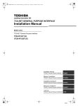
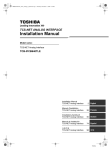
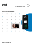
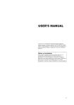
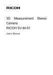
1
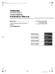
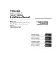
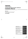
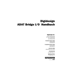
+00DE89308801_01EN_SVM_General_IF.book Page 1 Tuesday, January 20, 2009 6:44 PM FILE NO. A08-014 SERVICE MANUAL Model name: TCS-NET General Purpose Interface TCB-IFCG1TLE Toshiba +00DE89308801_01EN_SVM_General_IF.book Page 2 Tuesday, January 20, 2009 6:44 PM Service Manual TCS-NET General Purpose Interface SAFETY CAUTION The important contents concerned to the safety are described on the product itself and on this Service Manual. Please read this Service Manual after understanding the described items thoroughly in the following contents (Indications/Illustrated marks), and keep them. [Explanation of indications] Indication Explanation DANGER Indicates contents assumed that an imminent danger causing a death or serious injury of the repair engineers and the third parties when an incorrect work has been executed. WARNING Indicates possibilities assumed that a danger causing a death or serious injury of the repair engineers, the third parties, and the users due to troubles of the product after work when an incorrect work has been executed. CAUTION Indicates contents assumed that an injury or property damage (*) may be caused on the repair engineers, the third parties, and the users due to troubles of the product after work when an incorrect work has been executed. * Property damage : Enlarged damage concerned to property, furniture, and domestic animal/pet [Explanation of illustrated marks] Mark Explanation Indicates prohibited items (Forbidden items to do) The sentences near an illustrated mark describe the concrete prohibited contents. Indicates mandatory items (Compulsory items to do) The sentences near an illustrated mark describe the concrete mandatory contents. Indicates cautions (including danger/warning) The sentences or illustration near or in an illustrated mark describe the concrete cautious contents. WARNING Do not modify the products. Do not also disassemble or modify the parts. It may cause a fire, electric shock or injury. Prohibition of modification. For spare parts, use those specified (*). If unspecified parts are used, a fire or electric shock may be caused. *: For details, refer to the parts list. Use specified parts. Do not bring a child close to the equipment. Before troubleshooting or repair work, do not bring a third party (a child, etc.) except the repair engineers close to the equipment. It causes an injury with tools or disassembled parts. Please inform the users so that the third party (a child, etc.) does not approach the equipment. Connect the cut-off lead cables with crimp contact, etc, put the closed end side upward and then apply a water-cut method, otherwise a leak or production of fire is caused at the users’ side. Insulating measures Assembly/Cabling After repair work, surely assemble the disassembled parts, and connect and lead the removed cables as before. Perform the work so that the cabinet or panel does not catch the inner cables. If incorrect assembly or incorrect cable connection was done, a disaster such as a leak or fire is caused at user’s side. 2 Toshiba +00DE89308801_01EN_SVM_General_IF.book Page 3 Tuesday, January 20, 2009 6:44 PM Service Manual TCS-NET General Purpose Interface WARNING Insulator check After the work has finished, be sure to use an insulation tester set (500V mugger) to check the resistance is 2MΩ or more between the charge section and the non-charge metal section (Earth position). If the resistance value is low, a disaster such as a leak or electric shock is caused at user’s side. When checking the circuit inevitably under condition of the power-ON, use rubber gloves and others not to touch to the charging section. If touching to the charging section, an electric shock may be caused. Be attentive to electric shock After repair work has finished, check there is no trouble. If check is not executed, a fire, electric shock or injury may be caused. For a check, turn off the power breaker. Check after rerair After repair work (installation of front panel and cabinet) has finished, execute a test run to check there is no generation of smoke or abnormal sound. If check is not executed, a fire or an electric shock is caused. Before test run, install the front panel and cabinet. Check the following items after reinstallation. 1) The earth wire is correctly connected. 2) The power cord is not caught in the product. Check after reinstallation 3) There is no inclination or unsteadiness and the installation is stable. If check is not executed, a fire, an electric shock or an injury is caused. CAUTION Be sure to put on gloves (*) during repair work. If not putting on gloves, an injury may be caused with the parts, etc. (*) Heavy gloves such as work gloves Put on gloves When the power was turned on, start to work after the equipment has been sufficiently cooled. As temperature of the compressor pipes and others became high due to cooling/heating operation, a burn may be caused. Cooling check 3 Toshiba +00DE89308801_01EN_SVM_General_IF.book Page 4 Tuesday, January 20, 2009 6:44 PM Service Manual TCS-NET General Purpose Interface Contents 1. Outline . . . . . . . . . . . . . . . . . . . . . . . . . . . . . . . . . . . . . . . . . . . . . . . . . . . . . . . . . . . . . . 5 2. Required Devices and Tools . . . . . . . . . . . . . . . . . . . . . . . . . . . . . . . . . . . . . . . . . . . . 5 3. Checking the Board inside the TCB-IFCG1TLE . . . . . . . . . . . . . . . . . . . . . . . . . . . . . 5 4. Troubleshooting . . . . . . . . . . . . . . . . . . . . . . . . . . . . . . . . . . . . . . . . . . . . . . . . . . . . . . 6 4 Toshiba +00DE89308801_01EN_SVM_General_IF.book Page 5 Tuesday, January 20, 2009 6:44 PM Service Manual TCS-NET General Purpose Interface 1. Outline This document describes how to troubleshoot individual problems in interfacing with general-purpose devices using the TCB-IFCG1TLE. For information on Applications/Functions/Specifications, Installation, Connection of Power cable and Signal wires, Setting, Trial Operation Check, Connection to External Devices, and so on, see the Installation Manual of the TCB-IFCG1TLE. 2. Required Devices and Tools • • • • Screw driver (for +M4 screw) TESTER DYNA KIT (for TEST 4-3) The setting tool software for the advanced conjunction function for the general purpose interface must be installed on the PC (with Windows 2000, XP or later) for TEST 4-3. 3. Checking the Board inside the TCBIFCG1TLE In troubleshooting procedures described in Section 4 or later, you need to check the settings, connections, and LEDs of the board inside the case. Disconnect the DC plug of the AC adapter, remove the screws located in the four corners of the case lid, and open the lid of the case. Connect the DC plug again, and turn on the unit. 5 Toshiba +00DE89308801_01EN_SVM_General_IF.book Page 6 Tuesday, January 20, 2009 6:44 PM Service Manual TCS-NET General Purpose Interface 4. Troubleshooting Follow the flowchart show in 4-1to perform common checks that apply to every kind of troubleshooting. Is an appropriate AC adapter used? Are the voltage and polarity set correctly? YES Is the TCC-LINK connection (U1 and U2) made correctly? Is the address set correctly (SW1 and SW2)? YES Is the board operating normally in test mode? YES Are wires for functions to be used connected to the terminal block securely? Troubleshoot following problems by using the applicable procedure shown in 4-2 and its following. An air conditioning operation connected to the RO1 relay contact is not available from the central remote controller. Refer to 4-2. Air conditioning conjunction function is not available. Refer to 4-3. Temperature can not be measured. Refer to 4-4. RO1, RO2, RO3, and RO4 cannot be controlled. Refer to 4-5. DI input is unreadable. Refer to 4-6. AO output is not produced. Refer to 4-6. AI input is unreadable. Refer to 4-6. Details are described in the following sections using flowcharts. 6 Toshiba +00DE89308801_01EN_SVM_General_IF.book Page 7 Tuesday, January 20, 2009 6:44 PM Service Manual TCS-NET General Purpose Interface 4-1. Common Checks Be sure to always perform the checks shown in the flowchart below when a problem occurs. CAUTION The changes to DIP SW settings take effect after the SW7 RESET button is pressed or the unit is turned on again. Is an appropriate AC adapter used? Are the voltage and polarity set correctly? NO YES Is the TCC-LINK connection (U1 and U2) made correctly? Is the address set correctly (SW1 and SW2)? NO Use an appropriate power supply. Check that the POWER LED (LED D10) is lit in red. Check that the DC plug input is 15±0.5v. Check the voltages of 3.3V, 12V, and 5V with a tester as necessary. See the PCB layout diagram below that shows the locations of the checkpoints. Make the connection correctly, and use an appropriate address. For details, see Chapters 5 and 6 of the Installation Manual. Check the termination resistance setting of SW6 also. YES Is the board operating normally in test mode? To enable test mode, set SW2 as follows: 1 and 4 to ON; 2 and 3 to OFF. The D23, D24, D25, and D26 LEDs must be turned ON/OFF according to whether each bit of SW1 is ON or OFF. NO Replace the product. NO Connect the wires to the terminal block securely. YES Are wires for functions to be used connected to the terminal block securely? Visually check the terminal block to see if the stripped part of each wire is correctly placed between the contacts. Check continuity between each contact of the terminal block and the end of the corresponding wire with a tester. 7 Toshiba +00DE89308801_01EN_SVM_General_IF.book Page 8 Tuesday, January 20, 2009 6:44 PM Service Manual TCS-NET General Purpose Interface The PCB layout is shown below. Checkpoints are circled. 4-2. An air conditioner indoor unit connected to the RO1 and DI3 relay contacts using the HA connector cannot be operated from the central remote controller An air conditioning operation connected to the RO1 relay contact is not available from the central remote controller Is the relay mode set correctly (SW5)? SW5-2 and SW5-4 = OFF; SW5-3 = ON NO See the Installation Manual, and make the settings correctly. NO See the Installation Manual, and make the connection correctly. YES Are DI3/RO1 and the air conditioner HA connector connected correctly? See the chapter titled "WIRING" of the Installation Manual. 8 Toshiba +00DE89308801_01EN_SVM_General_IF.book Page 9 Tuesday, January 20, 2009 6:44 PM Service Manual TCS-NET General Purpose Interface 4-3. Conjunction function is not available Conjunction function cannot be set, or air conditioning operation is not available. (Using the setting tool software for the advanced conjunction function) Is the setting tool software for advanced conjunction function installed on the configuration PC? Is the connection to the TCBIFCG1TLE made correctly? Are values written correctly? NO See the setting tool manual for advanced conjunction function, and install the software and make the connection correctly. YES Is the setting value of SW5 correct? NO Make the following settings: 6 POSITION = ON; 5 POSITION = OFF. NO See the Installation Manual, and set the polarity, voltage level, and current level of the specified trigger port. YES Are the input polarity and level specified for the trigger port provided correctly? YES Is the address for central control of the specified air conditioner correctly registered using the setting tool software for advanced conjunction function? Conjunction function is not available. DI4/DI1 fixed trigger mode Is the setting value of SW5 correct? NO NO YES Are inputs to DI4 and DI1 provided correctly? NO See the setting tool manual for advanced conjunction function, and set the address of the applicable air conditioner correctly. Make the following settings: 5 POSITION = ON; 6 POSITION = OFF. See the Installation Manual, and check that the connection is made securely and an appropriate input current level and polarity are provided. 9 Toshiba +00DE89308801_01EN_SVM_General_IF.book Page 10 Tuesday, January 20, 2009 6:44 PM Service Manual TCS-NET General Purpose Interface 4-4. Temperature measurement can not be measured Temperature measurement can not be measured Is the specified thermistor connected to AI3 or AI4 correctly? NO Connect it correctly. YES Connect the DYNA KIT to CN5. Set SW2 as follows: 1 and 4 to ON; 2 and 3 to OFF. Press RESET SW7. Test mode is enabled. Start the communication software on the PC, and display the communication log in ASCII format. The calculated resistance value of the thermistor connected to AI3/4 is displayed at intervals of 1 second. Check that the value is correct by comparing it to the specified value. NO Replace the wire with a shielded one, or avoid induction from other wires. YES Are the TCB-IFMB640TLE and Modbus Master operating normally? NO Check the operation of the TCB-IFMB640TLE and Modbus Master. For details, see the manual of each device. 4-5. A relay contact cannot be controlled from the center controller RO1, RO2, RO3, and RO4 cannot be controlled Is the board operating normally in test mode? To enable test mode, set SW2 as follows: 1 and 4 to ON; 2 and 3 to OFF. The D23, D24, D25, and D26 LEDs must be turned ON/OFF according to whether each bit of SW1 is ON or OFF. NO Replace the product. YES Can the output pattern of RO1 and RO2 be set with SW5-1, 2, and 3? NO Replace the product. YES Are the TCB-IFMB640TLE and Modbus Master operating normally? NO Check the operation of the TCB-IFMB640TLE and Modbus Master. For details, see the manual of each device. 10 Toshiba +00DE89308801_01EN_SVM_General_IF.book Page 11 Tuesday, January 20, 2009 6:44 PM Service Manual TCS-NET General Purpose Interface 4-6. The port I/O value is unreadable or the port output value is not produced when the center controller is used Connect the DYNA KIT to CN5. Set SW2 as follows: 1 and 4 to ON; 2 and 3 to OFF. Press RESET SW7. Test mode is enabled. Start the communication software on the PC, and display the communication log in ASCII format. DI input is unreadable AO output is not produced AI input is unreadable For DI: In test mode, are the DI1, DI2, DI3, DI4, DI5 and DI6 levels displayed as H or L correctly according to the actual input in the communication software on the PC? NO YES Are the applied current value and polarity provided correctly? NO YES Are the TCB-IFMB640TLE and Modbus Master operating normally? For AO: In test mode, is 5 V output to AO2 and AO3? NO Check the input from the external circuit and the connection. Check the input from the external circuit and the connection. For the applied current value, refer to the regulation value in the installation manual. Check the operation of the TCB-IFMB640TLE and Modbus Master. For details, see the manual of each device. NO Replace the product. YES Are the TCB-IFMB640TLE and Modbus Master operating normally? For AI: In test mode, measure the AI5 and AI6 input values with a tester. Are they displayed at 1024 level in the communication software on the PC? NO NO Replace the product. YES Are the TCB-IFMB640TLE and Modbus Master operating normally? Check the operation of the TCB-IFMB640TLE and Modbus Master. For details, see the manual of each device. NO Check the operation of the TCB-IFMB640TLE and Modbus Master. For details, see the manual of each device. 11 Toshiba 23-17, TAKANAWA 3-CHOME, MINATO-KU, TOKYO, 108-0074, JAPAN Copyright © 2009 TOSHIBA CARRIER CORPORATION, ALL Rights Reserved. DE89308801 +00DE89308101_01EN_TCB-IFCG10TLE_gene_IM.book Page 1 Thursday, November 27, 2008 2:12 PM TCS-NET GENERAL PURPOSE INTERFACE Installation Manual Model name: TCS-NET General Purpose Interface TCB-IFCG1TLE (TCB-IFCG2TLE) Installation Manual TCS-NET General Purpose Interface 2 English Manuel d’installation TCS-NET General Purpose Interface26 Français Installations-handbuch TCS-NET General Purpose Interface50 Deutsch Manual de instalación TCS-NET General Purpose Interface74 Español TCS-NET General Purpose Interface98 Toshiba +00DE89308101_01EN_TCB-IFCG10TLE_gene_IM.book Page 2 Monday, December 15, 2008 3:49 PM Installation Manual TCS-NET General Purpose Interface • Thank you very much for purchasing this TOSHIBA TCB-IFCG1TLE (TCB-IFCG2TLE). • Please read this manual carefully beforehand for proper installation of the TCB-IFCG1TLE (TCB-IFCG2TLE). Contents 1 Precautions for Safety . . . . . . . . . . . . . . . . . . . . . . . . . . . . . . . . . . . . . . . . . . . . . . . . . 3 2 Introduction . . . . . . . . . . . . . . . . . . . . . . . . . . . . . . . . . . . . . . . . . . . . . . . . . . . . . . . . . . 5 3 Before Installation . . . . . . . . . . . . . . . . . . . . . . . . . . . . . . . . . . . . . . . . . . . . . . . . . . . . 7 4 Installation . . . . . . . . . . . . . . . . . . . . . . . . . . . . . . . . . . . . . . . . . . . . . . . . . . . . . . . . . . . 8 5 Connection of Power cables/Earth wires/Signal wires . . . . . . . . . . . . . . . . . . . . . . . 9 6 Setting . . . . . . . . . . . . . . . . . . . . . . . . . . . . . . . . . . . . . . . . . . . . . . . . . . . . . . . . . . . . . 12 7 Trial Operation Check . . . . . . . . . . . . . . . . . . . . . . . . . . . . . . . . . . . . . . . . . . . . . . . . 15 8 Input/Output Specifications . . . . . . . . . . . . . . . . . . . . . . . . . . . . . . . . . . . . . . . . . . . . 16 1-EN –2– +00DE89308101_01EN_TCB-IFCG10TLE_gene_IM.book Page 3 Monday, December 15, 2008 3:49 PM Installation Manual TCS-NET General Purpose Interface 1 Precautions for Safety Manual readers This manual is intended for those who have the required knowledge/Qualifications for electric or control and are in charge of any of the following: • Installation of the product • Design of the control system • Management of the site Agreements for use of this product (1) Scope of warranty If a failure occurs in this product as a result of our fault or negligence we will provide replacement or repair of the product. We will not be responsible if the fault occurs as a result of any of the following. • The product was handled or used under conditions/environment that are not specified in this manual. • The failure was caused by aspects outside of this product. • The product was altered or repaired by persons other than Toshiba Carrier. • The product was not used in accordance with its original purpose. • The cause of the failure was not foreseeable with our scientific and technical levels at the time of shipping. • The failure is due to a natural calamity, disaster, or the like. The warranty mentioned here shall cover only this product, and any damage and losses resulting from the failure of this product shall be excluded from the scope of warranty. (2) Restrictions of liability In no event shall we be liable for any special, indirect, or consequential damage arising out of or in connection with the use of this product. (3) Conditions for use of this product • When this product is to be used in combination with other products, the dealer or qualified professional shall check the applicable standards, specifications, laws, and regulations beforehand. The dealer or qualified professional shall also verify that this product conforms to the customer’s system, machines, and/or equipment in which this product is to be used. If the dealer or qualified professional fails to do so, we shall not be responsible for the conformity of this product. • When you wish to use this product for any of the following purposes, be sure to consult our sales staff and use this product with a margin of rating and performance, as well as take appropriate safety measures for safety circuit, mechanism, etc. that will minimize danger in case of a failure. * Use this product outdoors or for purposes that may cause latent chemical contamination or electrical interference or use under conditions/environment that are not specified in this manual. * Use this product in nuclear power control facilities, incineration facilities, railway/airline/vehicle facilities, medical equipment, amusement machines, safety devices, and equipment/facilities that are restricted by administrative organizations and/or respective industries. * Use this product in systems, machines, or equipment that may pose a danger to human life or properties. * Use this product in systems or facilities that require high reliability, such as gas/water/electricity supply systems and non-stop operation systems. * Use this product for other purposes that require a high level of safety. • Thoroughly understand and strictly observe all prohibitions and precautions for use stated in this manual to prevent contingent damage or losses to you or other persons due to improper use of this product. (4) Changes to specifications The specification described in this manual is subject to change for improvement or other reasons without notice. Contact our sales staff to confirm the latest specifications of this product. –3– EN 2-EN Toshiba +00DE89308101_01EN_TCB-IFCG10TLE_gene_IM.book Page 4 Monday, December 15, 2008 3:49 PM Installation Manual TCS-NET General Purpose Interface • Read these “Precautions for Safety” carefully before installation. • The precautions described below include important items regarding safety. Observe them without fail. • After the installation work, perform a trial operation to check for any problem. Explain how to use and maintain the unit to the customer. Ask the customer to keep this Installation Manual. WARNING • Ask an authorized dealer or qualified installation professional to install or reinstall the TCB-IFCG1TLE (TCBIFCG2TLE). Improper installation may result in electric shock or fire. • Turn off the main power supply switch or breaker before attempting any electrical work. Make sure all power switches are off. Failure to do so may cause electric shock. • Perform installation work properly according to this Installation Manual. Improper installation may result in electric shock or fire. • Do not modify the unit. Any modification may cause a malfunction, resulting in overheating or fire. CAUTION • Perform wiring correctly in accordance with the specified the current capacity. Failure to do so may result in short-circuit, overheating, or fire. • Connect the specified cables for the terminals securely to prevent external forces from affecting them. Failure to do so may result in disconnection, overheating, or fire. 3-EN –4– Toshiba +00DE89308101_01EN_TCB-IFCG10TLE_gene_IM.book Page 5 Monday, December 15, 2008 3:49 PM Installation Manual TCS-NET General Purpose Interface 2 Introduction Applications/Functions/Specifications Applications • The TCB-IFCG1TLE is provided with the following input/output ports through which the central controller* can control the output ports and read data from the input ports. The TCB-IFCG1TLE enables reading of ON/OFF information and sensor data of relay-connected indoor units and general devices, as well as various applied controls including voltage control of actuators, motors, etc. • The TCB-IFCG1TLE also enables sensor-based control of air conditioners such as air conditioner ON/OFF control with the change in digital input values of this board. * Full access can be made through the Modbus (TCB-IFMB640TLE) interface. However, RO1, RO2, DI3, and DI6 can be accessed or read from the TOSHIBA BMS central controller such as the 64-way central control remote controller (TCB-SC642TLE2). • Inputs and outputs are connected to an appropriate device in the external circuit. Digital inputs and outputs can handle binary values and analog inputs, outputs can handle linear values. 64 Central Remote controller Modbus Master (controller) Modbus (TCB-IFMB640TLE) TCC-LINK Indoor unit This product Digital output ON/OFF control Indoor unit Relay control coil Drive circuit input, etc. Digital input Binary state Indoor unit Motor, lighting, solenoid valve, ventilation fan, HA equipment Drive circuit Relay contact or open collector Sensors Transistor, etc. Illuminance, sense, fire alarm, etc. Analog input Temperature measurement EN Thermistor Analog input Linear input Analog output Linear control Operational amplifier output, etc. Sensors Buffer Illuminance, sense, fire alarm, etc. Operational amplifier input, etc. Buffer Drive circuit Motor, lighting, solenoid valve, etc. • Compatible Air Conditioners S-MMS, S-HRM, Mini-SMMS, DI, SDI –5– 4-EN Toshiba +00DE89308101_01EN_TCB-IFCG10TLE_gene_IM.book Page 6 Monday, December 15, 2008 3:49 PM Installation Manual TCS-NET General Purpose Interface Specifications Power supply 15 VDC ±5% Power consumption 4W Operating temperature/humidity 0 to 40 °C, 20 to 85% RH Storage temperature -20 to 60 °C Chassis material Galvanized sheet metal 0.8t (no coating) Dimensions 66 (H) × 170 (W) × 200 (D) mm Mass 820 g External View 200 1 6-Ø5 mounting holes 2 22 78 78 66 22 63.6 156 170 147 5 Bottom side 7 4 Top side 8 3 6 22 5-EN 78 78 22 Parts name Specifications Parts name Specifications 1 Case Galvanized sheet metal 5 Grommet C30-SG20A 2 Case lid Galvanized sheet metal 6 Grommet C30-SG20A 3 Grommet C30-SG20A 7 Grommet for power supply C30-SG20A 4 Grommet C30-SG20A 8 DC Jack MJ-40 –6– Toshiba +00DE89308101_01EN_TCB-IFCG10TLE_gene_IM.book Page 7 Monday, December 15, 2008 3:49 PM Installation Manual TCS-NET General Purpose Interface 3 Before Installation Check the following package contents. No. Item Quantity 1 TCB-IFCG1TLE (TCB-IFCG2TLE) 1 2 Installation Manual 1 3 Screw 4 Remarks M4 x 12mm tapping screws Use the following wiring materials to connect the signal lines and power lines. (Procured on site) No. 1 Line TCC-LINK Description Type 2-core shield wires Wire size 1.25 mm², 1000m max. 2.00 mm², 2000m max. (Total Length of TCC-LINK Network, includes indoor/outdoor connection.) Length Type 2 Signal Wire size Length 3 Power Multi-core wire Stranded wire, single wire *¹ 0.08097 mm² to 3.309 mm² (AWG28 to AWG12) Max. 20 m *² Specified by AC adaptor *¹ Use shielded wire according to the installation environment. Normally PVC cable is recommended. The conductor diameter should be approximately 0.7 mm and its resistance should be 60Ω/km. For 2-core cable, the outer diameter should be approximately 5 mm. *² Varies with use environment and conditions. An AC adaptor unit for this product must meet the following requirements and be procured locally. REQUIREMENT • Output: 15 V ±5% • Current: 0.5 A or more • Shall conform to applicable safety standards (including EN60950-1 or IEC 60950-1, etc), EMI standards (EN550022 and EN61000-3), and EMS standards (including EN50024, (EN61204-3), and EN61000-4). • Shall meet environmental conditions and required lifetime. • DC Plug 2.1mmØ (inner diameter) 5.5mmØ (outer diameter) 10mm (length) Recommended product is Model name: UI312-1508 produced by UNIFIVE TECHNOLOGY CO., LTD Homepage addresses of UNIFIVE TECHNOLOGY CO., LTD are http://www.unifive-us.com/, http://www.unifive.com.tw/, http://www.unifive.co.kr/, http://www.unifive.com/ or http:/ www.unifive-c.com/. –7– EN 6-EN Toshiba +00DE89308101_01EN_TCB-IFCG10TLE_gene_IM.book Page 8 Monday, December 15, 2008 3:49 PM Installation Manual TCS-NET General Purpose Interface 4 Installation TCB-IFCG1TLE (TCB-IFCG2TLE) Installation Method and Orientation There are five orientations of Surface/Wall Mount that the TCB-IFCG1TLE (TCB-IFCG2TLE) can be installed, these are shown below. NOTE Use screws supplied for installation of device. No good REQUIREMENT Do not install the unit in any of the following places. • Humid or wet place • Dusty place • Place exposed to direct sunlight • Place where there is a TV set or radio within one meter • Place exposed to rain (outdoors, under eaves, etc.) Installation Space and Maintenance Space A side space for connecting through cable inlets and an upper space for maintenance must be reserved before installation. The other sides can be adjacent to surrounding objects. 100mm 100mm 100mm 7-EN –8– Toshiba +00DE89308101_01EN_TCB-IFCG10TLE_gene_IM.book Page 9 Monday, December 15, 2008 3:49 PM Installation Manual TCS-NET General Purpose Interface 5 Connection of Power cables/Earth wires/ Signal wires CAUTION • Power lines have polarity. • The TCC-LINK signal lines have no polarity. REQUIREMENT Disconnect the AC adaptor for this appliance from the main power supply. • The AC adaptor for this appliance must be connected to the main supply by a circuit breaker or switch with a contact separation of at least 3 mm. Power cables/Earth wires/Signal wires Connect power cables, earth wires, and signal wires to the specified terminals on the terminal block as shown below. TCC-LINK communication line DC power input 15V ±5% CAUTION Polarity + - U2 U1 SWART CN5 Connect the shield of the TCC-LINK communication line to earth on the air conditioner side. Do not connect the shield wire to this board. It should be open and insulated. U1 and U2 have no polarity. SW7 Secure each cable with a cable clamp. LED TCC-LINK ERROR (RED) SW6 SW5 LED TCC-LINK (YELLOW) LED POWER SW1 SW2 EN AI3+- AI3- AI5+ AI5- AO2+-AO2AI4+- AI4- AI6+ AI6- AO3+-AO3-- RO1+RO1- RO3+RO3RO2+RO2- RO4+RO4- DI1+ DI1- DI3+ DI3- DI5+DI5DI2+ DI2- DI4+ DI4- DI6+ DI6- Secure each cable with a cable clamp. Analog input Relay output Digital input –9– 8-EN Toshiba +00DE89308101_01EN_TCB-IFCG10TLE_gene_IM.book Page 10 Monday, December 15, 2008 3:49 PM Installation Manual TCS-NET General Purpose Interface Analog input/output Digital output RO output 20 U1, U2 5 10 Length of stripped signal wires 5 Length of stripped TCC-LINK wires CAUTION To connect a wire to a wiring terminal on the signal terminal block, insert a screwdriver or the like into a wiring terminal opening hole at an angle of 45 degrees and raise the screwdriver end to open the wiring terminal as shown below. Insert a wire into the open wiring terminal in this state, and then lower the screwdriver end and remove from the terminal opening hole. Wiring terminal opening holes Open the wiring terminal Screwdriver or the like Wiring terminals Wiring terminal opening holes Wiring terminal opening holes Wiring terminals Wiring terminals Wiring terminal opening holes Wiring terminals Appearance of signal terminal block 9-EN Side view of signal terminal block – 10 – Toshiba +00DE89308101_01EN_TCB-IFCG10TLE_gene_IM.book Page 11 Monday, December 15, 2008 3:49 PM Installation Manual TCS-NET General Purpose Interface Wiring Connection The following displays an example of the TCB-IFCG1TLE connection to the TCC-LINK Network. The TCC-LINK communication lines are connected to the U1 and U2 terminal blocks on the TCB-IFCG1TLE board as shown below. Communication lines are connectable for both wires between indoor units and between outdoor unit and indoor units and for central control wires. NOTE The TCB-IFCG1TLE device can be connected to the TCC-LINK network on the indoor side using the U1 & U2 connections, OR on the outdoor side via the U3 & U4 connections. For connection to external devices through digital inputs/outputs and analog inputs/outputs, refer to “Connection to External Devices” in “8 Input/Output Specifications” Shield earthing The shield of the TCC-LINK Network wire should be connected on the air conditioner side and left open and insulated at the TCB-IFCG1TLE side. • U1 and U2 have no polarity. When connecting to multiple outdoor units or central control wires U1 U2 U3 U4 Outdoor unit U1 U2 U1 U2 TCC-LINK TCB-IFCG1TLE Modbus (TCB-IFMB640TLE) U1 U2 U3 U4 Central control remote controller Central control wires HA compatible air conditioner or relay control device Wires between indoor units and between outdoor unit and indoor units U1 U2 U1 U2 U1 U2 Indoor unit Indoor unit Indoor unit Modbus Master CONTROLLER U1 U2 TCC-LINK When connecting to multiple indoor units TCB-IFCG1TLE HA compatible air conditioner or relay control device EN Connecting HA Compatible Air Conditioner (When connecting to an air conditioner with JEMAcompliant HA terminals) (1) Set SW5-2 = OFF, SW5-3 = ON and SW5-4 = OFF on this board. (2) Detach the panel of the indoor unit to be connected. Connect the 4 Pin plug with four wires (length must be 1.9 m or less, insulator thickness must be 1 mm or more, procured locally) to the 4 Pin HA connector on the control board of the indoor unit. Consult the manufacturer of the air conditioner about the location of the HA terminals and the installation method. (3) Connect 1, 2, 3, and 4 of the four wires to RO1+, RO1-, DI3+, and DI3-, respectively. This board DI3DI3+DO1DO1+ Indoor unit HA connector (4) (3) (2) (1) (4) (1) – 11 – 10-EN Toshiba +00DE89308101_01EN_TCB-IFCG10TLE_gene_IM.book Page 12 Monday, December 15, 2008 3:49 PM Installation Manual TCS-NET General Purpose Interface 6 Setting + - U2 U1 SWART CN5 SW7 LED TCC-LINK ERROR (RED) SW6 SW5 LED TCC-LINK (YELLOW) LED POWER SW1 SW2 AI3+- AI3- AI5+ AI5- AO2+-AO2AI4+- AI4- AI6+ AI6- AO3+-AO3-- RO1+RO1- RO3+RO3RO2+RO2- RO4+RO4- DI1+ DI1- DI3+ DI3- DI5+DI5DI2+ DI2- DI4+ DI4- DI6+ DI6- 1. Setting Terminator Resistor for the TCC-LINK Communication Line The TCC-LINK consists of TCB-IFCG1TLE units only. When no multiple air conditioners or custom air conditioners are connected, set SW6-1 of only one TCB-IFCG1TLE unit to ON and insert a 100-ohm terminator resistor into the TCC-LINK bus. SW6-2 is not used. SW6 ON OFF 1 2 CAUTION Switch settings are ONLY registered at power ON and when the reset switch has been pressed. When changing DIP Switch settings, be sure to either power down, or press reset switch SW7 to enable changes to be registered. 11-EN – 12 – Toshiba +00DE89308101_01EN_TCB-IFCG10TLE_gene_IM.book Page 13 Monday, December 15, 2008 3:49 PM Installation Manual TCS-NET General Purpose Interface 2. Setting SW5 SW5 is used for address mode, relay output type, and link operation settings. SW5 ON OFF 1 2 3 4 5 6 SW5-1: Address setting selection OFF: Address is set with SW1 and SW2 ON: Address is set by the central controller * For details, see (1) and (2) in “3. Setting Addresses Using SW1 and SW2”. SW5-2: RO1/RO2 discrete output selection OFF: Pulse type ON: Static type SW5-3: RO1/RO2 discrete output pulse type selection OFF: 2 pulse outputs selection, ON: HA selection (ON/OFF alternatively) SW5-4: RO2 discrete output polarity selection * For details, see the table in “1. Functions” in “Digital Inputs and Outputs”. SW5-5: OFF or ON SW5-6: OFF or ON * For details, see the table in “3. Functions of DI4 and DI1 (TCB-IFCG1TLE only)” in “Digital Inputs and Outputs”. 3. Setting Addresses Using SW1 and SW2 SW1 SW2 ON OFF 1 2 3 4 1 2 3 4 An address set with SW1 and SW2 corresponds to the unit number of an indoor unit. When two or more general purpose interface units are used, do not set duplicated addresses. Always set SW2-3 and SW2-4 to OFF. (1) When setting central control addresses from the central controller Set SW5-1 to ON. This setting is available when setting or changing central control addresses from the central controller for a system containing VRF, DI/SDI indoor units, and the general purpose interface. Set a desired unit number with SW1 and SW2 according to the switch settings in the table below. The line address is registered as 31. At this time, the central control address of the general purpose interface is set by the central controller. Example) When central control address is set to 1 with SW1 and SW2, the unit number of the general purpose interface is 31-1. (2) When setting central control addresses using SW1 and SW2 Set SW5-1 to OFF. An address set with SW1 and SW2 is the central control address of the general purpose interface. Set central control addresses according to the requirement of the customer. The line address is registered as 31. Example) When central control address is set to 5 with SW1 and SW2, the unit number of the general purpose interface is 31-5 and the central control address is 5. When SW5-1 is set to OFF, the central controller cannot set any central control addresses. Set central control addresses different from those of indoor units. – 13 – EN 12-EN Toshiba +00DE89308101_01EN_TCB-IFCG10TLE_gene_IM.book Page 14 Monday, December 15, 2008 3:49 PM Installation Manual TCS-NET General Purpose Interface ▼ Setting central control addresses Address SW1 1 2 3 SW2 4 1 2 Address SW1 1 2 3 18 ● SW2 4 1 2 Address ● 33 ● 34 3 ● 19 ● ● 35 4 ● ● 20 ● ● ● 36 ● ● 37 ● ● 38 ● 21 ● 22 7 ● ● 23 ● ● ● 39 8 ● ● ● 24 ● ● ● ● 40 ● ● 41 ● ● 42 6 ● 9 10 ● ● 25 ● 26 ● ● 11 ● ● 27 ● ● ● 43 12 ● ● ● 28 ● ● ● ● 44 ● ● 29 ● ● ● 45 ● ● 30 ● ● ● 46 15 ● ● ● 31 ● ● ● ● 47 16 ● ● ● ● 32 ● ● ● ● ● 48 13 14 13-EN 2 17 ● 5 * 1 ● ● ● SW1 1 2 3 SW2 4 SW1 1 2 3 SW2 4 1 2 49 50 ● ● 51 ● ● ● ● ● 52 ● ● ● ● ● ● 53 ● ● 54 ● ● ● ● ● ● ● ● 57 ● ● 58 ● ● Address ● ● ● 2 ● ● ● 1 ● ● ● ● ● ● ● ● ● ● ● 55 ● ● ● ● 56 ● ● ● ● ● ● ● ● ● ● ● ● ● ● ● ● 59 ● ● ● ● ● ● ● 60 ● ● ● ● ● ● ● ● 61 ● ● ● ● 62 ● ● ● ● ● ● ● ● 63 ● ● ● ● ● ● ● ● ● ● 64 ● ● ● ● ● ● ● ● ● ● ● shows that the corresponding switch of SW1 and SW2 is set to ON. – 14 – Toshiba +00DE89308101_01EN_TCB-IFCG10TLE_gene_IM.book Page 15 Monday, December 15, 2008 3:49 PM Installation Manual TCS-NET General Purpose Interface 7 Trial Operation Check Before starting trial operation Check before starting trial operation Set all Indoor unit and TCB-IFCG1TLE central control addresses (DN03). NOTE These central control address MUST be different for ALL indoor units in a central control network. • Connect one central controller or one Modbus System (TCB-IFMB640TLE+one Master) to TCC-LINK BUS. Trial operation Operate the central controller and check the communication status between TCB-IFCG1TLE and central controller. Check that LED23 lights up when Relay 1 is turned on and goes out when Relay 1 is turned off. When controlling from Modbus System, check that the DI, RO, AI and AO values of TCB-IFCG1TLE are correct. For details, refer to the specifications of TCB-IFMB640TLE. EN – 15 – 14-EN Toshiba +00DE89308101_01EN_TCB-IFCG10TLE_gene_IM.book Page 16 Monday, December 15, 2008 3:49 PM Installation Manual TCS-NET General Purpose Interface 8 Input/Output Specifications Digital Inputs and Outputs 1. Functions The following signals can be set and their states can read through the Modbus (TCB-IFMB640TLE) interface. However, RO1, RO2 (*1), DI3, and DI6 can be accessed from a central controller such as the 64-way central control remote controller (TCB-SC642TLE2). DI6, DI5, DI4, DI1, DI2 and DI3 are photocoupler input signals. Transmit these input signals through contacts, a switch, or a sink device. For details of these signals, see the “Connection to External Devices”. Signal classification Digital output Digital input Relay contact output Type 1 Connector RO1+ RO1- RO2;+ RO2- 15-EN Port name DO1 DO2 DO3 DO4 DI1 DI2 DI3 DI4 DI5 DI6 Signal name Relay 1 ch output for general purpose interface Relay 2 ch output for general purpose interface Data item TCB-IFCG1TLE TCB-IFCG2TLE Output type “a” or “b” contact selectable “a” or “b” contact selectable Output point 4 2 Maximum contact current 1 A 1A Maximum contact voltage 250 VAC 30 VDC 250 VAC 30 VDC Input type Photocoupler insulation Photocoupler insulation Number of input points 6 1 Input resistance 100 Ω 100 Ω Minimum input ON current 2 mA 2 mA Maximum allowable input 30 mA ON current 30 mA Maximum input OFF current 0.05 mA SW5 -2 0.05 mA SW5 SW5 -3 -4 Operation In/ Out Relay contact output OFF OFF * Normally open. Closed for 250 ms when Relay 1 setup request is turned ON. (*1) OFF ON * Normally open. Closed for 250 ms each time Relay 1 setup request is turned ON or OFF. HA output type (*1) ON * * Normally open. Continuously closed when Relay 1 setup request is ON, and opened when Relay 1 setup request is OFF. (*2) Out Relay contact output OFF OFF ON Normally closed. Opened for 250 ms when Relay 1 setup request is turned OFF. (*1) OFF OFF OFF Normally open. Closed for 250 ms when Relay 1 setup request is turned OFF. (*1) OFF ON * Normally open. Closed when Relay 2 setup request is ON, and opened when Relay 2 setup request is OFF. ON * * Normally open. Closed when Relay 2 setup request is ON, and opened when Relay 2 setup request is OFF. Out RO3+ RO3(TCB-IFCG1TLE only) Relay 3 ch output for general purpose interface * * * Relay contact output. Normally open. Closed when Relay 3 setup request is ON, and opened when Relay 3 setup request is OFF. Out RO4+ RO4(TCB-IFCG1TLE only) Relay 4 ch output for general purpose interface * * * Relay contact output. Normally open. Closed when Relay 4 setup request is ON, and opened when Relay 4 setup request is OFF. Out – 16 – Toshiba +00DE89308101_01EN_TCB-IFCG10TLE_gene_IM.book Page 17 Monday, December 15, 2008 3:49 PM Installation Manual TCS-NET General Purpose Interface Connector SW5 -2 Signal name DI5 (TCB-IFCG1TLE only) SW5 SW5 -3 -4 On/off input for general purpose interface Operation In/ Out Used for Relay 1 ON/OFF input setting at hand. This signal switches on and off of Relay 1 when DI5 is opened for more than 100 ms and then closed for 100 ms. The output mode depends on SW5-1, -2 and -3. However, when the on-hand setting is disabled through TCC-LINK, this port setting is not available. IN IN DI6 (TCB-IFCG1TLE only) Alarm input for general purpose interface Alarm input Closed signal indicates an alarm DI4 (TCB-IFCG1TLE only) Din2 input for general purpose interface Din2 input DI1 (TCB-IFCG1TLE only) Din3 input for general purpose interface Din3 input DI2 (TCB-IFCG1TLE only) Din4 input for General Purpose I/F Din4 input DI3 Din1 input for general purpose interface HA input HA monitor input. Closed signal shows operation and open signal shows operation stop. IN IN IN IN (*1) Can be controlled by the central control remote controller, BMS central controller (such as the 64-way central control remote controller, or Modbus (TCB-IFMB640TLE). When DI3 contact input is ON, no transfer pulse is output even if ON instruction is issued. When DI3 contact input is OFF, no transfer pulse is output even if OFF instruction is issued. At this time, Relay 2 control through Modbus (TCB-IFMB640TLE) is disabled. (*2) Status request response indicates the contact state, but does not indicate the DI3 state. 2. Connecting Relay-Controlled Devices With respect to relay contacts of TCB-IFCG1TLE, there are four output types of the ON set signal and OFF reset signal sent to a device to be controlled, as described in “1. Functions.” Choose the most suitable type. For details, see the examples of relay circuit and the description of functions. The figure below shows the states of relay contacts of RO1, RO2, RO3, and RO4. on: relay close RO1 open RO2 open RO1 on: relay close open RO2 Static type off: relay open close RO2 Pulse type open on: relay close RO1 off off: relay close off: relay close SW5-3 ON SW5-4 ON SW5-2 OFF SW5-3 OFF SW5-4 OFF On: relay close Off :relay open SW5-2 OFF SW5-3 ON SW5-4 OFF On: relay close Off :relay open SW5-2 ON SW5-3 OFF SW5-4 Don’t care RO1,RO2,RO3,RO4 off SW5-2 OFF 3. Functions of DI4 and DI1 (TCB-IFCG1TLE only) EN The input states of the DI4 and DI1 ports can be acquired through the Modbus (TCB-IFMB640TLE) interface. Indoor units can be controlled (for operation stop, etc.) according to the DI4 and DI1 input states by the setting for Case 2 in the following table. Case 1 SW5- Functions of DI4 and DI6 -5 -6 OFF OFF DI4 and DI1 input states can be acquired through the Modbus (TCBIFMB640TLE) interface. Local linkage Not provided 2 ON OFF DI4 and DI1 input states can be acquired through the Modbus (TCBIFMB640TLE) interface. When the DI4 input state has changed from “Open” to “Closed” it is notified Provided simultaneously through the TCC-LINK line to turn off all indoor units. When the DI1 input state has changed from “Open” to “Closed”, all indoor units of group address 1 are turned off through the TCC-LINK line. 3 OFF ON SWART entry setup mode 4 ON ON Reserved Provided – 17 – 16-EN Toshiba +00DE89308101_01EN_TCB-IFCG10TLE_gene_IM.book Page 18 Monday, December 15, 2008 3:49 PM Installation Manual TCS-NET General Purpose Interface Analog Inputs and Outputs 1. Functions The following table lists available analog inputs and outputs. Input states of 4-channel analog input signals can be acquired, and 2-channel analog output signals can be output through the Modbus (TCB-IFMB640TLE) interface. Signal classification Analog input Type 1 AI3 Temperature AI4 measurement (thermistor input) Type 2 0-10V range Analog output 17-EN Port name 0-10V range AI5 AI6 AO2 AO3 Data item TCB-IFCG1TLE Input type A/D converter input Number of input points 2 Thermistor 5 KΩ, YSI’s product Each series of 44000, 45000, 46000, 48000, 55000 and 44900. Measurement error ±0.4°C (excluding thermistor measurement error) Measurement range -10 to 90°C Input type Resistor-divided A/D converter input TCB-IFCG2TLE 0 Resistor-divided A/D converter input Number of input points 2 2 Resolution 10 bits 10 bits Allowable input voltage range 0.0 V to 10.0 V 0.0 V to 10.0 V Input resistance 3 KΩ 3 KΩ Input connectable output resistance 50 Ω or less 50 Ω or less Conversion time 160 mS 160 mS Conversion error ± (Input voltage x 0.008 + ± (Input voltage x 0.008 + 0.05) V 0.05) V Output type Class-C push-pull Number of output points 2 Resolution 8 bits Output voltage range 0.0 V to 10.0 V Maximum output source current 10 mA Output connectable load resistance 1 KΩ or more Conversion time 10 µS Conversion error ± (Input voltage x 0.008 + 0.12) V 0 – 18 – Toshiba +00DE89308101_01EN_TCB-IFCG10TLE_gene_IM.book Page 19 Monday, December 15, 2008 3:49 PM Installation Manual TCS-NET General Purpose Interface Terminal name Input/output name AI3+ CH1 thermistor Analog Input input CH1 (TCBIFCG1TLE only) AI3- AI3 GND AI4+ CH2 thermistor Analog Input input CH2 (TCBIFCG1TLE only) AI4- AI4 GND AI5+ 0-10 V DC input Analog Input CH3 AI5- AI5 GND AI6+ 0-10 V DC input Analog Input CH4 AI6- AI6 GND AO2+ 0-10 V DC Analog Output output CH1 (TCBIFCG1TLE only) AO2- AO2 GND AO3+ 0-10 V DC Analog Output output CH2 (TCBIFCG1TLE only) AO3- AO3 GND Use and devices to be connected Remarks Thermistor: Use the YSI’s product (5 Kohms) or equivalent Values converted to Celsius temperature can be read to one decimal place through the Modbus (TCB-IFMB640TLE) interface. Thermistor: Use the YSI’s product (5 Kohms) or equivalent Values converted to Celsius temperature can be read to one decimal place through the Modbus (TCB-IFMB640TLE) interface. 0 to 10 V. For general sensors The buffer output is connected. Allocation of the Modbus (TCB-IFMB640TLE) input register (R) Values up to the third decimal place can be transmitted. 0 to 10 V. For general sensors The buffer output is connected. Allocation of the Modbus (TCB-IFMB640TLE) input register (R) Values up to the third decimal place can be transmitted. 0 to 10 V. For general actuators and input buffers Connected to the buffer input, resistance load, etc. Allocation of the Modbus (TCB-IFMB640TLE) holding register (R/W) Values up to the third decimal place can be transmitted. 0 to 10 V. For general actuators and input buffers Connected to the buffer input, resistance load, etc. Allocation of the Modbus (TCB-IFMB640TLE) holding register (R/W) Values up to the third decimal place can be transmitted. EN – 19 – 18-EN Toshiba +00DE89308101_01EN_TCB-IFCG10TLE_gene_IM.book Page 20 Monday, December 15, 2008 3:49 PM Installation Manual TCS-NET General Purpose Interface Connection to External Devices This product supports versatile applications including air conditioning through connections to various external devices such as sensors, key switches, drive circuit control input/output signals, and home automation equipment. Observe the following precautions when connecting this product to external devices. General safety precautions to be observed in the circuit design process • Be sure to install a safety circuit in the external control circuit so that the system will operate safely in the event of a malfunction or abnormality occurring in this product or a abnormality as a result of external factors. • Output signals of this product may be kept ON or OFF due to fusing or burnout of the output relay or damage of the output transistor. To protect against this problem, be sure to provide a safety circuit in the external control circuit so that the entire system operates safely. • Take fail-safe measures at the user side in case of a signal line disconnection or an abnormal signal due to power interruption. • The life of output relays depends greatly on the contact open/close conditions. When using them, be sure to verify the performance with actual relays under actual use conditions and then use them within the number of open/close times that will not affect the relay performance. Continuous use of a deteriorated relay may result in an insufficient insulation between circuits or a burnout of the relay. General precautions on system start-up • For systems that have a load that could be dangerous to humans and/or has equipment connected to the output circuit, be sure to disconnect the output wiring temporarily and then perform the operation test. • Before turning on the power supply, make sure that electrical specifications and wiring are all correct. REQUIREMENT • The electrical circuit to be connected to this product must be provided on the power supply secondary side and operate at a voltage of 42 V or less. • To protect the signals from noise interference use the correct shielded cable for wiring. • Connection to external relay To control the power supply primary side of an external circuit by the relay outputs RO1, RO2, RO3, and RO4 of this product, connect the control coil of the IEC-approved relay to RO1 to RO4 to achieve reinforced insulation from the power supply primary side including the external circuit and control the power supply primary side by the IEC-approved relay contacts. External circuit connected IEC-approved relay This product RO1, RO2, RO3, and RO4 contacts X1 X1 contact Primary side of the power supply IEC-approved relay for the primary side Reinforced insulation between X1 control coil side circuit and primary side circuit of the power supply including X1 contact. 19-EN – 20 – Toshiba +00DE89308101_01EN_TCB-IFCG10TLE_gene_IM.book Page 21 Monday, December 15, 2008 3:49 PM Installation Manual TCS-NET General Purpose Interface Relay connection ▼ Noise reduction for relay output When opening/closing a circuit of inductive load, connect a surge killer, diode or varistor in parallel with the load as shown below. Application Circuit examples Capacitor-resistor system Characteristics DC Y Y When the load is a relay or solenoid, its operate time is delayed. N Y The operate time is more delayed than the capacitor-resistor system. Y Y Some operate time is needed. Inductive load AC Diode system Inductive load Varistor system Inductive load ▼ RO1, RO2, RO3, and RO4 contacts Contacts are directly output. This product Relay G5NB 12 V (Omron) RO1+, RO2+, RO3+, RO4+ EN X1 RO1-, RO2-, RO3-, RO4- – 21 – 20-EN Toshiba +00DE89308101_01EN_TCB-IFCG10TLE_gene_IM.book Page 22 Monday, December 15, 2008 3:49 PM Installation Manual TCS-NET General Purpose Interface Examples of relay contact connection Refer to “2. Connecting Relay-Controlled Devices” Type Connection Pulse contact output RO1 ON/OFF: “a” contact output Home automation (HA) equipment operation Pulse contact output Both RO1 and RO2 ON/ OFF: “a” contact output Remarks Indoor unit HA terminals RO1+ (1) HA control input+ RO1- (2) HA control input- DI3+ (3) HA monitor output+ DI3- (4) HA monitor output - X1 RO1+ X1- RO1- RO2+ ON output OFF output RO2- Operation circuit X2 X1 Pulse contact output RO1 ON: “a” contact output RO2 OFF: “b” contact output SW5-2 = OFF SW5-3 = ON SW5-4 = OFF DI3+ -> DI3Shows indoor unit is operating when current is ON, and indoor unit stops when current is OFF. Relay contacts are turned ON when operation is started and stopped. X1 RO1+ X1- RO1- X2 ON output Operation circuit RO2+ OFF output RO2- SW5-2 = OFF SW5-3 = OFF SW5-4 = OFF X1 (“a” contact) and X2 (“b” contact) are auxiliary relays. X1 contacts are closed during a time period from RO1 ON output to RO2 OFF output. Connect a device to be controlled to the contacts of X1. SW5-2 = OFF SW5-3 = ON SW5-4 = ON X1 (a contact) is auxiliary relay. X1 contacts are closed during a time period from RO1 ON output to RO2 OFF output. Connect a device to be controlled to the contacts of X1. X1 Continuous contact output RO1, RO2, RO3, RO4 ON: “a” contact output RO1+ RO2+ RO3+ RO1- RO2- RO3- ON output X1 X2 X1 * 21-EN Xn ON output ON output X3 X2 X3 shows the control coil of an auxiliary relay, and Xn SW5-2 = ON SW5-3 = OFF X1 to X4 are auxiliary RO4+ relays. Each contact is used. RO4These contacts can be ON output Operation used directly for power line ON and OFF without circuit auxiliary relays within the X4 allowable range of current and voltage. When relays X1, X2, X3, and X4 are X4 used, connect a device to be controlled or power line to each contact. shows the contact of auxiliary relay Xn. – 22 – Toshiba +00DE89308101_01EN_TCB-IFCG10TLE_gene_IM.book Page 23 Monday, December 15, 2008 3:49 PM Installation Manual TCS-NET General Purpose Interface ▼ Examples of digital input connection HA terminal monitor output 5V 5V (3) DI1,DI2,DI3,DI4,DI5,DI6 DI1,DI2,DI3,DI4,DI5,DI6 (4) Contact Current sink 5V 5V Current sink Contact DI1,DI2,DI3,DI4,DI5,DI6 DI1,DI2,DI3,DI4,DI5,DI6 ▼ Examples of analog input connection 2K AD Converter + 0-10V AI5,AI6 1K - AI5-,AI6 + AD Converter AI3,AI4 Thermistor YSI 5K Note) Board side - EN REQUIREMENT Connect external connecting point groups AI5-/AI6-/AI7-/AI8- and AO2-/AO3-/AO4-/AO5- to the same earth point in each power supply system. – 23 – 22-EN Toshiba +00DE89308101_01EN_TCB-IFCG10TLE_gene_IM.book Page 24 Monday, December 15, 2008 3:49 PM Installation Manual TCS-NET General Purpose Interface ▼ Examples of analog output Note) buffer Board side AO2,AO3 DA Converter AO2-,AO3- AO2,AO3 DA Converter more than 20K AO2-,AO3- Advanced conjunction function Set SW5-5 to OFF and SW5-6 to ON. Connect the SWART connector CN5 on this board to the RS232C connector of the PC, and download several setting files to this product from the dedicated PC tool software. Then collaborative operation among various input ports, air conditioners, and relay contacts RO1 to RO4 can be set in detail. For how to download the setting files and their contents, see the manual specified separately. For the detail data, contact your dealer. Indication of LEDs The following LEDs light as follows: LED No. 23-EN LED color Lighting condition D10 Red Lights while power is supplied to this board. D11 Yellow Lights for 0.5 seconds during TCC-LINK transmission. D12 Red Lights while TCC-LINK transmission is halted. – 24 – Toshiba +00DE89308101_01EN_TCB-IFCG10TLE_gene_IM.book Page 25 Monday, December 15, 2008 3:49 PM Installation Manual TCS-NET General Purpose Interface MEMO ................................................................................................... ................................................................................................... ................................................................................................... ................................................................................................... ................................................................................................... ................................................................................................... ................................................................................................... ................................................................................................... ................................................................................................... ................................................................................................... ................................................................................................... ................................................................................................... ................................................................................................... ................................................................................................... ................................................................................................... ................................................................................................... ................................................................................................... ................................................................................................... ................................................................................................... ................................................................................................... ................................................................................................... ................................................................................................... ................................................................................................... ................................................................................................... ................................................................................................... ................................................................................................... ................................................................................................... ................................................................................................... ................................................................................................... ................................................................................................... ................................................................................................... – 25 – EN 24-EN Toshiba 23-17, TAKANAWA 3-CHOME, MINATO-KU, TOKYO, 108-0074, JAPAN Copyright © 2009 TOSHIBA CARRIER CORPORATION, ALL Rights Reserved.