1
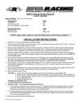
On back side of electrical support bracket pry back tab
securing starter relay. Remove starter relay from
support bracket.
Carefully remove bus bar from row ‘D’ by prying ends
UP evenly. Do not remove one end or work side to side
Remove rubber seal plugs from locations ‘D11, E11, &
F11’ by pressing a small screwdriver into openings on
top of fuse box. Seals will pop out at underside.
Lay electrical support bracket down in hull. Locate fuse
box. Squeeze top of tabs (2) on each side of fuse box
lid. Lift up to remove.
D11
E11
F11
- FUSE PANEL REFERENCE -
At underside of fuse panel insert one end of red wire
(supplied item #4) into location ‘D11’. (Listen for a click!)
Pull back on wire to ensure terminal is locked in place.
NOTE: Rows A, B, E & F contain 11 cavities.
Rows C, D, G & H contain 12 cavities.
Word doc. Part # RS11090-SCOM-11 © H1 2/27/12
5