1
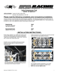
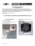
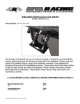
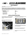
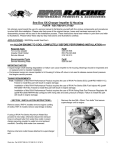
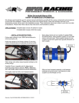
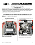
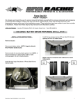
Pro-Series ECU
PART# - RY11841-ECU-HFPWC
APPLICATION(S): Yamaha 1.8L Engine Models (SHO/HO)
RIVA/Athena ECU Manager Web Site: www.rivaracing.com/Athena
In order to achieve optimal performance gains you will need to install the following RIVA Performance Products:
Products
RIVA Power Filter
OEM Intercooler Upgrade Kit (SHO models)
RIVA Supercharger Impeller (SHO models)
RIVA Fuel Pressure Regulator Kit
RIVA Intake Manifold Upgrade Kit
RIVA Engine Cooling Upgrade Kit *
RIVA Power Cooler Kit (SHO models)
‘R’ Series Pump Impeller
* = Required to provide safe operating parameters for all levels of modification (including stock).
Along with the above components we recommend many others that will complement the RIVA/Athena ECU providing
improved performance in acceleration, handling and top speed. Please visit www.rivaracing.com/kits to review the
complete list.
Required tools
Cut-off Wheel or Small Saw
Part#
N/A
Recommended tools
Service Manual
Part#
Please Call
Word doc. Part # RY11841-ECU-HFPWC© H1 11/15/12
1
- INSTALLATION INSTRUCTIONS Remove seats and rear storage bin.
Cut a slot in the electrical box cover using a cut-off
wheel or small saw. NOTE: Sand edges so they are
smooth.
Disconnect battery cables. NOTE: Negative (black)
first. Positive (red) second.
Remove rear grab handle/seat support if equipped.
Remove electrical box cover (2 locking tabs at top).
Remove material
on angled section.
(Approx. 5” long X 1-3/4” wide)
Disconnect stock ECU (3 electrical connectors at
bottom). NOTE: Document order of connectors.
Remove only the upper most warning sticker on
electrical box cover. Clean area with a non-residual
cleaner.
Place Power
Connector cradle at
edge of raised area.
Install supplied stainless steel cradle onto outside of
electrical box cover just below remaining warning
sticker. Secure using supplied hardware. NOTE: Install
bolts (2) from inside and nuts on outside of
electrical box cover. Do not over tighten.
Word doc. Part # RY11841-ECU-HFPWC© H1 11/15/12
Remove stock ECU (4 bolts). Retain stock hardware.
2010~08 FX-SHO models only:
Proceed to page 5 and follow
steps through completion of
installation.
All other Yamaha 1.8L models,
proceed to page 3.
2
Install RIVA/Athena ECU into electrical box and secure
using stock bolts (4). NOTE: Apply blue Loctite to
bolts. Do not over tighten.
Place Power Connector box on top of exhaust pipe.
Extend stock ECU connectors (3) towards motor.
Replace electrical box cover. Carefully slide into place
so that wiring harnesses fit into cut out.
Secure electrical box cover (2 locking tabs at top).
Connect stock ECU connectors (3) to Power Connector.
NOTE: Do not force. Verify order/location.
Listen/feel for click when locked in place.
On back of Power Connector remove adhesive backing
on Dual Lock. Carefully place Power Connector into
cradle on electrical box cover. Use Power Connector to
attach Dual Lock to electrical box cover.
At lower, right side of electrical box loosen zip securing
wiring harness to electrical box. Extend wiring harness
towards left side of electrical box.
At lower, right side of electrical box tighten zip tie
securing wiring harness to electrical box.
Inside front storage compartment remove rivets (5)
securing service lid in place. NOTE: Press pin at center
inward.
Connect Power Connector to ECU. NOTE: Do not
force connector into ECU. Once inserted use
locking arm to complete connection and secure.
OPEN / UNLOCKED
Remove service lid and locate remote control sensor.
CLOSED / LOCKED
Word doc. Part # RY11841-ECU-HFPWC© H1 11/15/12
3
Disconnect electrical connector and install supplied
block-off into wiring harness connector. NOTE: Make
sure block-off ‘snaps’ into place.
NOTE: If a RIVA/Vi-PEC ECU was previously installed
you must swap the black block-off with the supplied blue
block-off.
Secure bypass module to OEM wiring harness using
supplied zip tie.
Replace service lid and secure using stock rivets.
Replace rear grab handle/seat support if removed
Reconnect battery cables. NOTE: Positive (red) first.
Negative (black) second.
NOTE: ECU is equipped with our Stage 3 Base Map.
Verify required parts to run this map safely or download
others by going to www.rivaracing.com/Athena, click on
Yamaha and then ‘Base Maps’ in the left navigation.
Check bilge for tools, rags, etc. Run craft on a flush kit
to check for proper operation.
IMPORTANT:
The following documents, in order, are provided on the RIVA/Athena ECU Manager Web Site.
Please go to ‘www.rivaracing.com/Athena –> Yamaha –> Downloads’ to obtain the following files.
1.
2.
3.
4.
PC Software (Maya) – Install before proceeding.
Installing Maya – PDF file outlining Maya installation process.
Using Maya – PDF file outlining how to use Maya.
Connecting to ECU – PDF file outlining how to connect Maya (PC) to ECU.
Remember, the water belongs to everyone.
Please ride responsibly and respect the environment!
Technical Support
For answers to questions regarding installation or trouble shooting RIVA Performance Products contact:
RIVA Technical Support directly at (954) 247-0705 or by e-mail at [email protected].
Limited Warranty
RIVA/Athena Pro-Series ECU’s carry a 1-year limited warranty to the original purchaser. They are warranted to be free of defects in materials and workmanship under
normal use and service. Customer modified components will be void of warranty. This warranty is limited to defects in the primary components only. Finish and/or wear
marks in or on primary components are not covered under this warranty.
RIVA Racing’s liability is expressly limited to the repair or replacement of the components contained within or associated with this kit. RIVA Racing agrees to repair or at
RIVA’s option, replace any defective unit without charge, if product is returned to RIVA Racing freight prepaid within the warranty period. Any equipment returned which, in
RIVA’s opinion, has been subjected to misuse, abuse, overheating or accident shall not be covered by this warranty.
RIVA Racing shall have no liability for special, incidental or consequential damages or injury to persons or property from any cause arising from the sale, installation or use
of this product.
No other warranty, express or implied, including, but not limited to the implied warranties of merchantability and fitness for a particular purpose, applies. Various states do
not allow for the limitation of incidental or consequential damages and therefore the above exclusion or limitation may not apply to you.
Warranty does not include the expenses related to freight or transportation of parts or compensation for any inconvenience or loss of use while being repaired. A copy of
the original invoice and a Return Authorization Number (RA#) must accompany all warranty claims.
Warranted replacement parts will be returned freight collect.
Word doc. Part # RY11841-ECU-HFPWC© H1 11/15/12
4
2010~08 FX-SHO Models ONLY
Remove mounting tab on right side of relay box backing
plate.
INSTALLATION INSTRUCTIONS -
Remove ECU electrical box (4 bolts) from hull.
Disconnect Slant Detection Switch1. Remove electrical
system relay box (2 bolts) from electrical box.
1
Install relay box backing plate onto electrical box
backing with one original bolt. Push relay box backing
plate towards bolt, check to make sure it’s level and
then secure.
Remove relay box backing plate (6 bolts).
Remove electrical box backing plate from hull and set
aside.
Locate and drill 1/4” hole through electrical box backing
plate.
Remove relay box backing plate from electrical box.
Word doc. Part # RY11841-ECU-HFPWC© H1 11/15/12
5
Replace relay box backing plate onto relay box using
only 5 original bolts. NOTE: Apply blue Loctite to
threads. Do not over tighten bolts.
Replace electrical box backing plate (4 bolts) onto hull.
NOTE: Apply blue Loctite to threads. Do not over
tighten bolts.
Install RIVA/Athena ECU onto electrical box and secure
using stock bolts (4). NOTE: Apply blue Loctite to
bolts. Do not over tighten.
Do not use.
Replace relay box onto electrical box backing plate
using one original bolt. At opposite side use supplied
M6 bolt, washer and spacer to secure relay box to
electrical box. NOTE: Apply blue Loctite to threads.
Do not over tighten bolts.
Place supplied
spacer between
relay box and
electrical box.
At lower, right side of electrical box loosen zip securing
wiring harness to electrical box. Extend wiring harness
towards left side of electrical box.
Supplied M6 bolt
and washer
securing relay
box to electrical
box.
Word doc. Part # RY11841-ECU-HFPWC© H1 11/15/12
6
Connect Power Connector to ECU. NOTE: Do not
force connector into ECU. Once inserted use
locking arm to complete connection and secure.
OPEN / UNLOCKED
At lower, right side of electrical box loosen zip securing
wiring harness to electrical box. Extend wiring harness
towards left side of electrical box.
CLOSED / LOCKED
Place Power Connector box on top of exhaust pipe.
Extend stock ECU connectors (3) towards motor.
Replace electrical box cover. Carefully slide into place
so that wiring harnesses fit into cut out.
IMPORTANT NOTE: If a RIVA/Vi-PEC V88 ECU was
previously installed remove the cable splicer installed
inline with black & white wires at lower right side of
electrical box and reconnect OEM wires directly.
Secure electrical box cover (2 locking tabs at top).
Connect stock ECU connectors (3) to Power Connector.
NOTE: Do not force. Verify order/location.
Listen/feel for click when locked in place.
Inside front storage compartment remove rivets (5)
securing service lid in place. NOTE: Press pin at center
inward.
Remove service lid and locate remote control sensor.
On back of Power Connector remove adhesive backing
on Dual Lock. Carefully place Power Connector into
cradle on electrical box cover. Use Power Connector to
attach Dual Lock to electrical box cover.
Word doc. Part # RY11841-ECU-HFPWC© H1 11/15/12
7
Disconnect electrical connector and install supplied
block-off into wiring harness connector. NOTE: Make
sure block-off ‘snaps’ into place.
Replace service lid and secure using stock rivets.
Replace rear grab handle/seat support if removed
Reconnect battery cables. NOTE: Positive (red) first.
Negative (black) second.
NOTE: ECU is equipped with our Stage 3 Base Map.
Verify required parts to run this map safely or download
others by going to www.rivaracing.com/Athena, click on
Yamaha and then ‘Base Maps’ in the left navigation.
Check bilge for tools, rags, etc. Run craft on a flush kit
to check for proper operation.
Secure bypass module to OEM wiring harness using
supplied zip tie.
IMPORTANT:
The following documents, in order, are provided on the RIVA/Athena ECU Manager Web Site.
Please go to ‘www.rivaracing.com/Athena –> Yamaha –> Downloads’ to obtain the following files.
1.
2.
3.
4.
PC Software (Maya) – Install before proceeding.
Installing Maya – PDF file outlining Maya installation process.
Using Maya – PDF file outlining how to use Maya.
Connecting to ECU – PDF file outlining how to connect Maya (PC) to ECU.
Remember, the water belongs to everyone.
Please ride responsibly and respect the environment!
Technical Support
For answers to questions regarding installation or trouble shooting RIVA Performance Products contact:
RIVA Technical Support directly at (954) 247-0705 or by e-mail at [email protected].
Limited Warranty
RIVA/Athena Pro-Series ECU’s carry a 1-year limited warranty to the original purchaser. They are warranted to be free of defects in materials and workmanship under
normal use and service. Customer modified components will be void of warranty. This warranty is limited to defects in the primary components only. Finish and/or wear
marks in or on primary components are not covered under this warranty.
RIVA Racing’s liability is expressly limited to the repair or replacement of the components contained within or associated with this kit. RIVA Racing agrees to repair or at
RIVA’s option, replace any defective unit without charge, if product is returned to RIVA Racing freight prepaid within the warranty period. Any equipment returned which, in
RIVA’s opinion, has been subjected to misuse, abuse, overheating or accident shall not be covered by this warranty.
RIVA Racing shall have no liability for special, incidental or consequential damages or injury to persons or property from any cause arising from the sale, installation or use
of this product.
No other warranty, express or implied, including, but not limited to the implied warranties of merchantability and fitness for a particular purpose, applies. Various states do
not allow for the limitation of incidental or consequential damages and therefore the above exclusion or limitation may not apply to you.
Warranty does not include the expenses related to freight or transportation of parts or compensation for any inconvenience or loss of use while being repaired. A copy of
the original invoice and a Return Authorization Number (RA#) must accompany all warranty claims.
Warranted replacement parts will be returned freight collect.
Word doc. Part # RY11841-ECU-HFPWC© H1 11/15/12
8