1
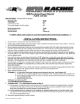
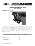
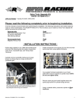
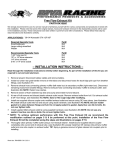
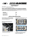
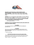
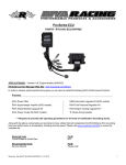
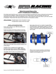
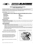
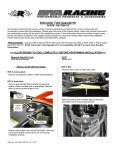
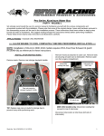
Performance Power Filter Kit PART# - RK13100 We strongly recommend the use of a service manual to familiarize yourself with the various components and procedures involved with this installation. Please note that some of the original clamps, hoses and hardware removed in the disassembly process will be used in the installation process. These instructions have been written in step-by-step format and refer to illustrations. We suggest reading through the instructions entirely before performing installation. Please follow these step-by-step instructions and illustrations carefully. APPLICATION(S): Kawasaki Ultra 300 models ALLOW ENGINE TO COOL COMPLETELY BEFORE PERFORMING INSTALLATION - INSTALLATION INSTRUCTIONS - Remove ECU bracket by carefully prying ends away from bulkhead. STOCK AIR INTAKE REMOVAL Inside front storage compartment remove storage tray. Remove upper inspection hatch. Word doc. Part # © H1 DATE 1 Identify electrical connectors (5). Disconnect and remove ECU bracket. Remove bolts (6) securing seat stay bracket1 and throttle controller2. 5 1 4 2 1 2 3 Disconnect throttle controller electrical wire. Move throttle controller and ignition coil bracket aside. Tuck wire loom inside and to the left as you are facing front of craft. Remove emissions hoses (3) from stock air box. Cut and remove zip tie securing vent tubes together. Move tubes aside. 1 2 3 Remove seats. Word doc. Part # © H1 DATE 2 Remove hose between air box and catch can and discard. Retain spring clamps. Disconnect fuel tank filler hose from fuel tank. Loosen clamp securing air inlet tube to supercharger inlet. IMPORTANT: Seal fuel tank opening to prevent emission of fumes and debris from entering tank. Remove air box support bracket between tank and hull. Cut zip ties (2) around air box. Split stock air box in half by releasing locking tabs around outer edge using a small flat screwdriver TIP: Remove bolts securing bracket to hull first. They can be accessed behind handlebar pad. Word doc. Part # © H1 DATE 3 Remove top half of air box through front inspection hatch and discard. Remove air box inlet duct and filter. Remove air inlet tube between air box and supercharger inlet. Retain clamps (2). Carefully rotate bottom half of air box clockwise as you are facing front of craft. Carefully insert Power Filter tube assembly into hull through front inspection hatch. Rotate into place so that coupler is aligned with supercharger inlet. NOTE: Take care not to damage small tube at supercharger inlet. Replace throttle controller using only two stock bolts1. Insert supplied M6 x 40mm bolt2 into third location. NOTE: Apply blue Loctite to bolts. Do not over tighten. 1 2 Carefully remove bottom half of air box through front inspection hatch and discard. POWER FILTER INSTALLATION Install supplied coupler onto end of supplied Power Filter tube. Secure using one stock clamp. NOTE: Do not over tighten clamp. Place second stock clamp over supercharger inlet. Loosely install supplied bracket onto Power Filter tube using supplied hardware. NOTE: Apply blue Loctite to threads. Install Power Filter tube coupler onto supercharger inlet but do not secure. Raise Power Filter tube so that bracket lines up with M6 x 40mm bolt. Secure Power Filter bracket using supplied M6 washer and nylock nut. NOTE: Do not over tighten. Install supplied Power Filter and Pre-filter onto Power Filter tube. NOTE: Do not over tighten clamp. Word doc. Part # © H1 DATE 4 Tighten bolts (2) securing Power Filter tube to bracket. NOTE: Do not over tighten bolts. Replace ignition coil and seat stay brackets. NOTE: Apply blue Loctite to bolts. Do not over tighten. Tighten clamp securing Power Filter tube coupler to supercharger inlet. NOTE: Do not over tighten clamp. Reconnect throttle controller electrical wires. Replace fuel filler hose. NOTE: Do not over tighten clamp. Reconnect electrical connectors (5) at ECU bracket. Replace ECU bracket. Replace front inspection hatch cover. Check bilge for tools, rags, etc. Run craft on a flush kit to check for proper operation. Remember, the water belongs to everyone. Please ride responsibly and respect the environment! Technical Support For answers to questions regarding installation or trouble shooting RIVA Performance Products contact: Install bypass hoses onto Y-fitting on Power Filter tube. Secure using stock clamps. NOTE: Do not over tighten clamps. RIVA Technical Support directly at (954) 247-0705 or by e-mail at [email protected]. Limited Warranty RIVA Power Filter Kits carry a 1-year limited warranty to the original purchaser. They are warranted to be free of defects in materials and workmanship under normal use and service. Customer modified components will be void of warranty. This warranty is limited to defects in the primary components only. Finish and/or wear marks in or on primary components are not covered under this warranty. RIVA Racing’s liability is expressly limited to the repair or replacement of the components contained within or associated with this kit. RIVA Racing agrees to repair or at RIVA’s option, replace any defective unit without charge, if product is returned to RIVA Racing freight prepaid within the warranty period. Any equipment returned which, in RIVA’s opinion, has been subjected to misuse, abuse, overheating or accident shall not be covered by this warranty. RIVA Racing shall have no liability for special, incidental or consequential damages or injury to persons or property from any cause arising from the sale, installation or use of this product. No other warranty, express or implied, including, but not limited to the implied warranties of merchantability and fitness for a particular purpose, applies. Various states do not allow for the limitation of incidental or consequential damages and therefore the above exclusion or limitation may not apply to you. TIP: Install first hose as far as possible. Before installing second hose twist as if unscrewing so you can thread it past first hose. Install supplied breather hose between catch can and open fitting on Power Filter tube between bypass hoses and inlet. Secure using stock spring clamps. Word doc. Part # © H1 DATE Warranty does not include the expenses related to freight or transportation of parts or compensation for any inconvenience or loss of use while being repaired. A copy of the original invoice and a Return Authorization Number (RA#) must accompany all warranty claims. Warranted replacement parts will be returned freight collect. 5