1
Once the gauge is removed, save the clamp as it will be reused with the new MCL gauge.
Remove the small gauge with 5/16” wrench or nut driver
Save Clamp, and reuse for install
INSTALLATION OF NEW MCL-GPS17 GAUGE
Install the new gauge into the fairing using the original clamp, along with the supplied nuts. Be
sure the alignment tab on the clamp lines up with the notches in the fairing when tightening the clamp
back up, flat side down.
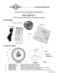
SWITCH/DIM PLUG SENDER POWER (+12V Key ON)
GROUND WIRING
This gauge is designed to replace the factory air temperature gauge and will plug into the stock
three pin connector with no modifications. The two pin bulb connector will not be used and can be taped
up or secured using zip ties.
If the wiring harness plug is not available, wire according to the drawing on next page. Standard
¼” female spade connectors can be used to make a connection to the gauge.
The second connector toward the top of the back side of the gauge is where the supplied
Switch/Dim harness connects. Both inputs are “triggered” when there is +12V on either wire.
BLUE Wire (Dim Input)
The BLUE wire is used for optional night time dimming function. When this wire receives
+12V the gauge will dim to about ½ brightness.
GREEN Wire (Switch Input)
The GREEN wire is used for a switch input for entering setup. This wire can be wired to a
momentary push button switch and the other side of the switch to +12V. The wire can
also be stripped back and touched to +12V to enter setup and then taped off once
complete.
(Wiring diagram on next page)
2 Manual # 650453