1
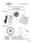
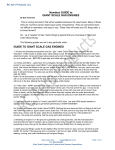
Factory gauge plug Dim and Switch Back View of Gauge
Switch Input (active high +12V)
GREEN wire
Dim Input (active high +12V)
BLUE wire
+12V
+12V
Optional toggle
switch
Optional momentary
push button switch
KEY ON POWER
+12V
KEY ON POWER
Sender
(to stock air temperature sensor)
KEY ON POWER
Connect to main
chassis ground
If you are replacing a gauge in a set of Dakota Digital gauges, plug the small, white, two-pin
connector into the compass gauge just as it was on the other gauge you removed. If you are adding this
gauge to the set rather than replacing one (you will have a total of 5 small Dakota Digital gauges on the
bike) you will need to locate any one of the other BLUE and GREEN wires going to the other gauges in
the set, cut and splice into the new harness. Match BLUE to BLUE and GREEN to GREEN. If you are
installing multiple MCL-3K gauges without a Dakota Digital Speedometer, you can tie the GREEN wires
together and then to one switch. The same is true for the BLUE wire, wire all of them to one switch.
If you have an MCL-3K Tachometer, it will actually serve as the dimming “switch”. The BLUE
wire on any of the MCL-3K Tachs will provide a +12V output for the dimming function. The gauge has a
light sensor behind the lens and when the ambient light is dim or low it will “turn on” the output and
supply +12V to the BLUE wire. You will not need to wire in a toggle switch if you have an MCL-3K
tachometer and choose to wire it this way.
Back View of Gauges
Dim Input (+12V)
BLUE wire
+12V
KEY ON POWER +12V
KEY ON POWER
Optional toggle
switch
Switch Input (+12V)
GREEN wire
Optional momentary
push button switch
3 Continue wiring to other
MCL-3K gauges
Manual # 650453