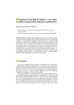
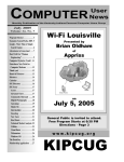
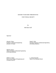
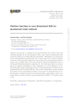
1
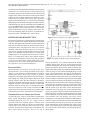
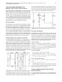
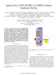
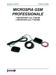
MIT International Journal of Electrical and Instrumentation Engineering, Vol. 2, No. 1, Jan. 2012, pp. (14-18) ISSN 2230-7656 (c) MIT Publications 14 Practical Simulation of Power System Protection Laboratory Experiments Using Construction-wise Classified Relays Kalpesh J. Chudasama Electrical Engineering Department A.D. Patel Institute of Technology New V.V. Nagar, Gujart, India e-mail: [email protected] Hardik Shah Electrical Engineering Department A.D. Patel Institute of Technology New V.V. Nagar, Gujart, India Brijesh Patel Electrical Engineering Department A.D. Patel Institute of Technology New V.V. Nagar, Gujart, India ABSTRACT Power system protection is a key part of the power system. The course is offered in undergraduate disciplines worldwide. Howsoever the conventional protection philosophy rapidly changing from electromechanical and static to numerical relay technology it will take a long time for complete substitution in developing countries. It is very important for graduating students and faculties with respect to relaying education and research to have theoretical and practical knowledge of both conventional and numerical protection. This paper discusses the practical simulation of laboratory experiments of power system protection regular course offers in Degree engineering and polytechniques institutes using one example for each construction wise classified relays like electromagnetic, static and digital relays. This paper explains and provides help to understand such kind of experiment development in educational engineering institute for relaying education and future research work to the electrical engineering faculties and students and to understand the operational behavior of relays to the field engineers. This paper discusses the detail understanding of the some practical simulation of real power system protection. Keywords: TMS (Time Multiplier Setting), TOC (Time Operating Characterstic), Overcurrent (O/C), Overload (O/L), Potential Transformer (P.T.), Current Transformer (C.T.) INTRODUCTION As we all know the power system is cater huge energy demands and it is spread over in big area containing many major and costlier components like Generator, Transformers, Transmission lines, Induction motors, Bus bars etc. Modern power system is going to be more and more complex. The effective, fast, accurate and reliable protection of such power is system not only necessary but must; otherwise it can cause large revenues losses. Previously Electromagnetic and static relays was the major part of protective system. Static relays have many advantages over elecromagnetic like low burden, no moving parts, fast response, precise characteristic, and sensitivity, miniaturization, less maintenance, low resetting time, low overshoot and transient overreach. Static relays have some limitations like sensitive to voltage spikes, variation of characteristic with temperature and age, overload capacity and reliability as in [01]. With the developments in VLSI technology, microprocessors that appeared in seventies have evolved and have made remarkable progress in recent years. Numerical relays are finds its major important because of many advantages over electromagnetic and static relays. The inherent advantage of microprocessor-based protective schemes, over the existing static relay is their flexibility due to its programmable approach, fast, more accurate and reliable relaying. It can provide protection with low cost and compete with conventional relays. A number of characteristics can be realized using the same interface [2],[6] discussed Laboratory used for teaching, design and conducting research in area of microprocessor based relays.[3] To model large variety of power system behavior utilized offline digital transient simulation programme and find relay response.[4] discussed a Power System Protection Laboratory at the Energy Research Centre utilized computer simulation and relay testing station for enhancing teaching and research in relay education.[5] designed wired and commissioned Laboratory projects of Power System and Power System Protection through senior design projects. The present paper gives real field exposure and calculations, by simulating the protective scheme, taking example of each construction wise classified relays. The motive of the paper is to provide practical exposure and practical aspects of power MIT International Journal of Electrical and Instrumentation Engineering, Vol. 2, No. 1, Jan. 2012, pp. (14-18) ISSN 2230-7656 (c) MIT Publications 15 system protection through understanding the protection using construction wise specified relays which are utilizing in developing countries to the students and some extent to field engineers also. Industry also in need of well practical trained students so their in-house training period and cost can be reduced. We have simulated here reverse power protection scheme with electromagnetic reverse power relay, transformer differential protection scheme with static relay and overcurrent, with numerical relay. All relay used for the practical simulation are of ALSTHOM make. Now it is known as AREVA. This paper intended to present idea about how to develop the practical simulation using any company make relays. The practical simulation tables for the above experiments are prepared in power system laboratory of the institute. REVERSE POWER PROTECTION Figure 1: Power circuit for reverse power protection Reverse power protection is required against reversal of power in a power system. Power normally flows from the alternators to the bus. If the input to the prime-mover of any of alternators stops, the bus bar starts feeding the alternator and it runs as synchronous motor. The prime mover will act as a load on the motor. This means the flow of power is reversed. This does not pose any harm for the alternator but the reversal of power is very harmful to the prime mover. For small steam turbines relays are set to operate when forward power reduces below 3% of rated power and for large turbines sensitive setting of 0.5% of rated power is used. These relays are known Figure 2: Control circuit for reverse power protection as Low Forward Power Relay. Hydro-turbine relays are set to operate at 3% of reversal of power Gas turbine relays are and one off position. 1 no. position represents the normal set to operate for 10% reversal of rated power. condition means power flows in forward direction from generator to infinite bus bars. While 2 no. positions of switch Protective Relay presents the turbine (prime mover) faulty condition. The Reversal of power is sensed by a reverse power relay. It is a toggle switch used as steam valve interlock. Initially the Rotary directional relay with leading maximum torque angel. Switch is put up on 1no. Position and MCB put up on with Ref.[7] is the manual of ALSTHOM make CCUM-21 toggle switch in off position. Pressing on push button the Definite Time Reverse Power relay used for the practical circuit work healthy and no relay operation was observed. simulation. CCUM high speed induction cup unit initiates a Once the contactor energized the steam valve interlock toggle static timing unit which provides output contacts for alarm switch is change to on position to represents that steam supply and trip contacts. Power flow direction can be checked by is given to turbine. The steam valve interlock is used to prevent sensing the magnitude and sign of power. The construction is the mal operation of relay under manual starting and stopping induction cup type. Under healthy condition or under fault of the generator. If contactor is put up on with toggle switch condition where the current flow is in normal direction the on position then alarm will sound but reverse power relay relay does not operate. As the reversal of current occurs, the will not operate as per the control circuit designed for the torque in the reverse direction causes moving system to rotate simulation. The reverse power relay is only trips when rotary and close the trip contacts, and actuate the circuit breaker. switch is on position 2 and the same procedure mention above followed up. If one want to stop generator then first the toggle Simulated Protective Scheme and Circuits switch should put off (means steam cutoff) otherwise alarm As shown in Figure 1 Power circuit mainly contains MCB, sound without relay flag dropout. The toggle switch Rotary switch, Single phase variable rheostatatic load of arrangement is used in practical simulation to understand the maximum capacity of 10A, P.T., C.T., Toggle switch to concept of steam valve interlock used in the field in this kind represent steam valve interlock. Figure 2 Control circuit of conventional protection. Reverse power relay and alarm contains mainly same MCB, on- off and reset push buttons, sound simultaneously in the simulation only when reverse contacts and coil of contactor and reverse power relay power occurs. During manual start and stop without taking CCUM21. Connections were done as per circuit diagram. The care of steam valve interlock Relay will not operate but the rotary switch shown in Figure 1 has two on (1 & 2) alarm sounds. MIT International Journal of Electrical and Instrumentation Engineering, Vol. 2, No. 1, Jan. 2012, pp. (14-18) ISSN 2230-7656 (c) MIT Publications 16 TRANSFORMER DIFFERENTIAL PROTECTION USING STATIC RELAY wave shape monitoring facility relay not operate for no of times no load starting check. For normal load and the external fault relay not operate. Relay operates only for internal faults. Differential protection of transformer is used to protect the Figure 4 represents the control circuit of the simulation. power transformers from internal faults. As we know that there many problems in transformer differential protection like different voltage ratings and current ratings of primary and secondary side, Current transformers ratio and phase angel errors, internal phase shift, tap changing, Magnetizing inrush current, saturation of transformer core. There are also remedies for each problem very well discussed in [1] Main is to use bias differential relay for the differential protection. Protective Relay The simulation of the practical consist protection of single phase transformer of only 1 KVA using ALSTHOM make Static bias differential single phase relay MBCH12. This relay is high speed bias differential relay suitable for the protection Figure 4: Control circuit for power transformer protection of two or three winding power transformers. The relay is extremely stable during through faults even under condition Practical Calculations of CT saturation and during condition of ratio unbalance resulting from tap changing and CT errors and provides high In filed application of differential protection for 3 phase power speed operation for internal faults. Relay has features of transformer many steps are to be followed like current calculations at HT and LT side, ICT calculations, Tap setting, magnetizing inrush restraint and over-excitation restraint. Ratio error of CT and ICT etc;. For this laboratory simulation Simulated Protective Scheme and Circuits setup for checking relay operation against magnetizing inrush, The main equipments used in Figure 3 are single phase 230/ internal short circuit and external short circuit the following 110 V transformer; current transformers, Bias differential relay calculations done as per the equipment utilized. (MBCH-12) as in [7] and rheostats to simulate the scheme.S3 and S2 are the toggle switch for creating short circuit in primary and secondary winding respectively. S3 switch used for creating external (through) fault. To limit the fault current rheostat are used in series with the toggle switches used for creating internal and external faults. We can test the relay behavior for the different conditions like magnetizing inrush current normal load, external fault internal fault. Normal condition Current in transformer secondary winding I2 = 110V ÷ 185ohm = 0.59A, Current in CT(25/5A) at transformer secondary i2 = 0.59 ÷ 5 = 0.118A, Current in transformer primary I1 = (0.59×110) ÷ 230 = 0.28A, Current in CT (10/5) at transformer primary I1= 0.28 ÷ 2= 0.14. Under internal fault R = (18 × 185) ÷ (185 + 18) = 16.4 ohm, Current through short circuit = 6.7A, I2 = 0.59 A, I2 = 0.1189 A, I1= 3.2A, I1=1.6A, (i1-i2) =1.48A > basic setting, (i1 i2) ÷ ((i1+ i2) ÷2) = 1.72 Under external fault condition I2 = 6.7A, I2 = 1.34 A, I1= 3.2A, I1=1.6A, (i1-i2) = 0.26A (i1-i2) ÷ ((i1+i2) ÷2) = 0.17. The Bias setting of the relay is set up for 20%. The will relay not operate for external fault and will operate for internal primary or secondary short circuit fault. Figure 3: Power circuit for power transformer protection OVER CURRENT PROTECTION WITH DIGITAL RELAY For magnetizing inrush at no load position (S4 open), Overcurrent protection characteristics are plotted for RITXAutotransformer supply increased to 230V and on pushbutton 210 digital relay using CFB test kit [9] is the manual for the pressed relay not operate. As MBCH-12 has harmonic restraint test kit. MIT International Journal of Electrical and Instrumentation Engineering, Vol. 2, No. 1, Jan. 2012, pp. (14-18) ISSN 2230-7656 (c) MIT Publications Protective Relay 17 and extremely inverse characteristics by giving input to only 1 and 2 terminal from CFB test kit and output relay of P3 Ref. [8] RITX-210 is the manual for ALSTHOM make connected to CFB test kit relay contact input. digital relay which have also optional communication version availability. It can protect one, two or three phase applications Overcurrent Protection (Standard Inverse against overcurrent, short circuit, overload, non-directional earth fault and over temperature. It can control contactor or Current Time Characteristic, I) Settings circuit breaker. These relay has many facilities to use. In Operating Characteristic: toc 1 (Toc 1: Standard inverse), laboratory we have tested the flush mounted version of RITX- Current setting: 3.00 (relay rated current: 1A), TMS: 0.1, 210 with ALSTHOM relay testing kit for overcurrent, overload Configuration of Protection: On 1 (1: Enable to trip). condition. The relay has also facility to exchange information with a supervisory system. The relay front panel view LED display, LED indicators, Key pad and rear end output relay terminals, control i/p terminals RS 485 terminals etc;. LED display displays the phase current values. Six LED indicators for different protection like overload (Ip), over current (I>), short-circuit (I>>), earth fault (Io), over temperature (in cooperation with PTC sensors), Remote protection input (ZZ). Simulated Protective Scheme and Circuits Figure 6: Stanadard inverse definete Minimum characterstic (I>), TOC = 1 Figure 5: Connection diagram for RITX-210 relay As shown in Figure 5 for flush mounted arrangement of RITX 210 relay current input is given to 1 and 2 from relay testing Kit. Auxiliary supply is connected at A1-A2 of Vx. Four output available in C version. Output contacts can assign to the following terminal connection of the relay: 13-14 (p1 relay), 23-24 (p2 relay), 33-34(p3 relay), and 41-42-44 (p4 relay). It is possible to change the relay setting only in OFF-LINE mode. All output relay configuration procedure and other facilities detail are very good given as in [8]. We have configured output relay P3 relay to P3-1 using navigating Keypad. P3-1 means P3 relay contacts are energized if tripping of any protection which is set to trip take place. There is also configuring mode of operation available that can be set p3c-0 or p3c-1. 0 means no latching after energizing means relay is self-reset if a cause for its energizing ceases and for 1 latching of the energized relay until it is reset from the device key pad or adequately communication link or input S1-S2. It is configured p3c-0 for laboratory purpose. The relay is tested for overcurrent protection for standard inverse, very inverse, Figure 7: Very inverse Inverse Definete Minimum characterstic (I>), TOC = 2 Figure 8: Extremely Inverse Definete Minimum characterstic (I>), TOC = 3 MIT International Journal of Electrical and Instrumentation Engineering, Vol. 2, No. 1, Jan. 2012, pp. (14-18) ISSN 2230-7656 (c) MIT Publications Time taken for the relay to trip for current ranging from 3A to 6.4 A was noted as shown in Table 1. P3 was enabled 1 and p3c enabled 0. Graph for current/time for different characteristic is plotted in Figure 6 The same procedure repeated for tms = 0.2 and tms = 0.3. Similar settings and procedure repeated for toc 2 (Very inverse I-t charactsestic) and toc 3 (extremely inverse I-t characteristic) and plotted in Figure 7 and Figure 8 respectively with readings in Table 2 and Table 3 respectively. Table 1: Current-time readings for standard inverse I-t characteristic at different TMS I(A) 3.5 4 4.5 5 5.5 6 TMS=0.1 4.6 2.5 1.6 1.4 1.1 0.9 0.8 0.7 (sec) TMS=0.2 8.9 4.6 3.1 2.4 2.2 2 1.7 1.5 4 2.7 2.4 2 top 3 TMS=0.3 14.4 6.6 4.8 2.9 6.4 Table 2: Current-time readings for very inverse I-t characteristic at different TMS I(A) 3.5 4 3.5 2.3 2.1 1.5 (sec) TMS=0.2 15.4 6.5 4.3 3.4 2.7 top 3 TMS=0.1 7.8 4.5 5 TMS=0.3 24.4 10.5 6.5 5 3.9 5.5 6 6.4 1.2 1.1 0.9 2.3 1.9 1.7 3.3 2.9 2.4 Table 3: Current-time readings for extremely inverse I-t characteristic at different TMS I(A) 3.5 4 4.5 5 5.5 6 6.4 top TMS=0.1 8.5 5.3 3.8 2.7 2 1.6 1.7 (s) TMS=0.2 17 10.2 6.7 5.1 4.2 3.4 2.8 TMS=0.3 26 14.9 10.3 8 6.2 5.1 4.6 RESULTS The laboratory experiments simulated and tested using all kind of relays means Electromagnetic, Static and Numerical relay Which is important to especially developing countries like india where these relays are widely utilized and not discussed with detail understanding in other these kind of work. Reverse power protection experiment simulated to show that relay operates only while reverse power occurs and also steam valve interlock facility incorporated. Transformer protection simulated using static relay which operate only for primary and secondary short circuit while not operate for external or starting with no load (Magnetizing inrush) or load conditions. Numerical relay tested for standard inverse, very inverse and extremely inverse characteristics using a Relay testing kit which 18 can also be tested by making piratical arrangement using contactors and rheostats. CONCLUSION All protection set up are Laboratory set up and mainly to provide the idea about the operation of real field protection application. Such kind of laboratory simulation is very helpful for relaying education and research work. For the reverse power protection without using real turbine, generator set up simulation is made to give understanding the reverse power protection operation also considering steam valve interlock. Transformer differential protection employed in field for large power transformer and here it is simulated using only 1 KVA transformer. For power transformer differential protection there are no of things included in relay settings like CT errors, ICT errors, tap changing effects etc; here these things are not considered. By practical simulation using MBCH-12 static bias differential relay single phase transformer tested for magnetizing inrush, internal fault and external fault. RITX210 digital relay is used for testing overcurrent protection and protection for different characteristic using relay testing kit. This paper also provides the idea about how to develop the practical simulation using any company make relay. REFERENCES [1] Dr. M.A. Date, Prof. B.A. Oza, Dr. N.C. Nair, Power System Protection, Bharti Prakshan, Second Reprint 2004, Gujarat, India, pp. 61-62 & pp.196-206. [2] M.S. Sachdev, T.S. Siddu, A Laboratory for Research and Teaching of Microprocessor based Power System Protection, IEEE Transactions on Power Systms, Vol. 11, No. 2, May 1996. [3] M.A. Redfern, R.K. Agrawal, A Personal Computer Based System for the Lab Evaluation of High Performance Power System Protection Relays, IEEE Transactions On Power Delivery, Vol. 6, No. 4, Oct. 1991. [4] Wei-JenLee, Jyh-cherng, Ren-Junli and Ponpranod Didsayaburta, A Physical Laboratory for Protective Relay Education, IEEE Transactions on Education, Vol. 45, No. 2. [5] Bhuvanesh Oza and Sukmar M. Brahma, Development of Power System Protection Laboratory through Senior Design Projects, IEEE Transactions on Power Systems, Vol. 20, No. 2, May 2005. [6] Ahmed H. Eltom and Ruspat Hamchotipum, Microprocessor Based Relay Laboratory with Industry Support, IEEE, 2002. [7] ALSTHOM LTD., Catalogues of CCUM21 and MBCH-12 Relays. [8] ALSTHOM LTD., RITX- 210 user manual. [9] ALSTHOM LTD., Instruction and Maintenance ManualType CFB.