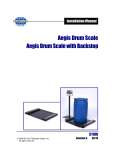
1
Installation Manual
Reliant Series
Floor Scale
Model: 3300
© 2005 by Fairbanks Scales.
All rights reserved
50783
Issue 2 10/06
Amendment Record
Reliant Series Floor Scale
Model: 3300
50783
Manufactured by Fancor
821 Locust
Kansas City, Missouri 64106
Created
03/05
Issue 1
Issue 2
03/05
10/06
New Product
Added NTEP and CWM Cerficate of Conformance numbers
Disclaimer
Every effort has been made to provide complete and accurate information in this manual. However, although this manual may
include a specifically identified warranty notice for the product, Fancor makes no representations or warranties with respect to the
contents of this manual, and reserves the right to make changes to this manual without notice when and as improvements are
made.
10/06
2
50783
Issue 1
Table of Contents
Section 1:
General Information
A. Introduction . . . . . . . . . . . . . . . . . . . . . . . . . . . . . . . . . 4
B. Specifications . . . . . . . . . . . . . . . . . . . . . . . . . . . . . . . 4
Section 2:
Installation
A. General Service Policy . . . . . . . . . . . . . . . . . . . . . . . . 5
B. Overview . . . . . . . . . . . . . . . . . . . . . . . . . . . . . . . . . . 5
C. Unpacking . . . . . . . . . . . . . . . . . . . . . . . . . . . . . . . . . . 6
D. Safety . . . . . . . . . . . . . . . . . . . . . . . . . . . . . . . . . . . . . 6
E. Installation Procedure . . . . . . . . . . . . . . . . . . . . . . . . . 7
Section 3:
Calibration
A. Calibration Procedure . . . . . . . . . . . . . . . . . . . . . . . . . 8
Section 4:
Accessories
A Introduction . . . . . . . . . . . . . . . . . . . . . . . . . . . . . . . . . 9
B. Bolt Down Plates . . . . . . . . . . . . . . . . . . . . . . . . . . . . . 9
C. Ramps . . . . . . . . . . . . . . . . . . . . . . . . . . . . . . . . . . . . 9
D. Bumper Guards . . . . . . . . . . . . . . . . . . . . . . . . . . . . . 10
E. Balance Junction Box . . . . . . . . . . . . . . . . . . . . . . . . .10
Section 5:
Maintenance and Service
A. Errors . . . . . . . . . . . . . . . . . . . . . . . . . . . . . . . . . . . . 14
B. Load Cell Replacement . . . . . . . . . . . . . . . . . . . . . . . 14
C. Foot Assembly Replacement . . . . . . . . . . . . . . . . . . . 15
D. Balance Junction Box/ PCB Replacement . . . . . . . . . .15
Section 6:
Parts
A. Parts List . . . . . . . . . . . . . . . . . . . . . . . . . . . . . . . . . . 17
B. Optional Accessories Parts List . . . . . . . . . . . . . . . . . .17
Appendix I: Accessories
A. Ramps and Bumper Guards . . . . . . . . . . . . . . . . . . . .19
B. Bolt Down Plates and Eybolts . . . . . . . . . . . . . . . . . . .19
C. Balance Junction Box . . . . . . . . . . . . . . . . . . . . . . . . .19
10/06
3
50783
Issue 2
Section 1: General Information
A.
Introduction
The Reliant Series floor scale is a general purpose scale designed for basic weighing
applications which require the platform to be installed and relocated in a minimal amount of
time. It is available in two different models and has several different optional accessories which
may be added to the scale. These optional accessories include ramps, bumper guards, and
bolt down plates.
B.
Specifications
Model:
Product Number:
3300
25690
25691
Part Number:
Capacity:
e MIN:
n MAX:
83701
2500 lb
0.5 lb
5000
83702
5000 lb
1 lb
5000
Platform size:
4’ x 4’
4’ x 4’
Capacity
1000 lb
2500 lb
Material:
Mild Steel
Resistance:
1000 Ohm
Rated Output:
Safe Overload:
Compensated Temp Range:
Safe Operating Temp Range:
2 mV/V
150 %
-10° C to 40° C
-10° C to 40° C
Load Cell Specifications:
NTEP CC:
05-032
CWM CC:
AM-5579
Note:
The Reliant series floor scale is designed for general purpose applications and will not
accomodate concentrated loading such as forklift traffic. Severe damage to the scale will occur
and will void any warranties, written or implied.
10/06
4
50783 Issue 2
Section 2: Installation
A.
General Service Policy
Prior to installation, it must be verified that the equipment will satisfy the customer's
requirements as supplied, and as described in this manual. If the equipment cannot satisfy the
application and the application cannot be modified to meet the design parameters of the
equipment, the installation should not be attempted.
It is the customer/operator's responsibility to ensure the equipment provided by Fairbanks is
operated within the parameters of the equipment's specifications and protected from accidental
or malicious damage. Other than the procedures authorized in the Operating manual, no
service, repair, or adjustments may be performed by unauthorized / untrained service
personnel. Any unauthorized repairs will void any verbal, implied, or written warranties.
B.
Overview
1.
These instructions apply to the floor scale and its specific installation
procedures. The procedures for instruments, printers and other peripherals are
given in manuals specifically provided for those units.
2.
All mechanical calibrations and or adjustments required to make this equipment
perform to accuracy and operational specifications are considered to be part of
the installation, and are included in the installation charge. Only those charges
which are incurred as a result of the equipment's inability to be adjusted or
calibrated to performance specifications may be charged to warranty.
3.
Absolutely no physical or electrical modifications are to be made to this
equipment. Electrical connections other than those specified may not be
performed, and physical alterations (holes, etc.) are not allowed.
4.
Before the installation is considered complete, the equipment is to be calibrated
to meet or exceed any applicable weights and measures requirements, if
applicable. The installing technician is responsible to make certain customer
personnel are fully trained and familiar with the capabilities and limitations of the
equipment. Be prepared to recommend the arrangement of components which
will provide the most efficient layout, utilizing the equipment to the best possible
advantage. The warranty policy must be explained and reviewed with the
customer.
10/06
5
50783 Issue 2
C.
Unpacking
1.
Check that all components are on hand, and agree with the customer's order.
2.
Remove all components from their packing material, checking to make certain
that all parts are accounted for and no parts are damaged. Advise the shipper
immediately if damage has occurred. Order any parts necessary to replace
those which have been damaged. Keep the shipping container and packing
material for future use. Check the packing list.
D.
3.
Collect all necessary installation manuals.
4.
Perform an inspection, making certain all hardware and electrical connections are
secure.
Safety
As is the case with any material handling equipment, certain safety precautions should be
observed during operation:
1.
Never load the platform beyond its rated capacity. Refer to the rating on the serial
number plate of the platform.
2.
Ensure that any structure which supports the platform is capable of withstanding
the weight of the platform plus its rated capacity load.
10/06
3.
Do not load the platform if there is any evidence of damage to the platform or
supporting structure.
4.
Use safety chains or other suitable restraining devices if there is any possibility of
the load shifting, falling, or rolling from its position on the platform.
6
50783 Issue 2
E.
Installation Procedure
1.
Select a location which is level and will fully support the weight of the platform plus
a full capacity load.
2.
Remove the top of the crate and all packing/banding material.
3.
Screw the two (2) eyebolts into the threaded adapters in the platform top. Use a
forklift or other lifting means along with chains, cables, or nylon straps to remove
the scale from the crate bottom.
~Caution~
Failure to use the proper lifting tools may result in personal injury.
4.
Set the scale so the interface cable exits in a direction where it can be protected.
If possible, use a cable protector to reduce trip hazards and protect the interface
cable from being damaged.
5.
Wire the scale interface cable to the proper type indicator using the following
platform wiring/ color code:
Cable Wire Color
Black
Green
Yellow
White
Red
10/06
Function
(-) Excitation
Analog Instrument
(-) Excitation
(+) Excitation
Shield
(+) Signal
(-) Signal
(+) Excitation
Shield
(+) Signal
(-) Signal
7
50783 Issue 2
Section 3: Calibration
A. Calibration Procedure
1.
Adjust the analog indicator to the platform. First, ensure all corners are within one
(1) division of each other at 25% of rated capacity. Follow the appropriate
indicator service manual to calibrate the instrumentation.
a.
Perform a coarse platform calibration which will be close to the actual
weight.
b.
Identify the platform’s corner numbers.
c.
Place a concentrated weight (25% of platform capacity) on corner 1, note
the displayed weight, move the weight to corner 2, note the displayed
weight, move and note the displayed reading on each of the remaining
corners.
d.
If corners require adjustment:
1.
Refer to the Maintenance and Service Section A Errors
chart.
e.
10/06
Final Calibration
1.
Remove all weights.
2.
Zero the indicator.
3.
Perform a final calibration with test weights.
4.
Follow the appropriate indicator service manual’s calibration
procedures to ensure a proper calibration.
8
50783 Issue 2
Section 4: Accessories
A.
Introduction
The Reliant series floor scales have several accessory options available. These accessories
are Bolt-down plates, Ramps, and Bumper-Guards.
B.
Bolt-Down Plates
Bolt down plates are used to keep the scale from sliding or moving when loads are applied. The
plates are bolted via anchors at each of the scale’s feet.
1.
Installation
a.
Place the platform in position.
b.
Place the bolt-down plate under the foot, plate edge extending out from
under the scale.
c.
Drill the two (2) holes using a hammer drill. Insert anchors with the nut
and washer already ON. Tap the anchor into the hole, then tighten the
nuts securely. Repeat this process for each plate used.
Note:
If ramps are NOT installed and bolt-down plates are needed, a set of four bolt-down plates will
be required.
C.
Ramps
Each mild steel ramp accessory comes with two integral bolt down plates and four anchors.
1.
Installation
a.
Place the ramp in position, then lift and set the platform feet into the boltdown plate holes.
b.
Drill the two (2) holes using a hammer drill. Insert the anchors with the
nut and washer already ON. Tap the anchor into the hole then tighten the
nuts securely.
• If two ramps are installed, NO other bolt-down plates are needed.
• If one ramp is installed, a set of two bolt-down plates is needed
• Only two ramps total may be installed on opposite sides of a
scale platform.
10/06
9
50783 Issue 2
D.
Bumper Guards
Bumper Guards are designed to help protect the platform from abuse resulting from ensuing
forklift traffic. The guards are slightly higher than the scale and will help deflect the forks.
Place the bumper guard so it will protect the platform from nonscale traffic, but
will not touch or interfere with the platform’s movement.
2.
Drill the holes using a hammer drill. Insert anchors with the nut and washer
already ON. Tap the anchor into the hole, then tighten the nuts securely.
Balance Junction Box
Installation
a.
Remove the scale access cover plate.
b.
Check that all load cells have wire markers on the cable ends. If not,
identify load cells with wire markers or other means, then disconnect the
load cell wires and the main interface cable wires.
c.
Dress all wires in order to be inserted into terminal blocks.
d.
Remove balance junction box cover and loosen all gland fittings.
e.
Insert the cables into the gland fittings and connect the cables to the
appropriate terminal block. The load cell cable for load cell number one
(1) will connect to the terminal block designated one (1). This process will
continue for all four (4) load cell cables. The main interface cable will
connect to the terminal block opposite the load cell terminals.
f.
Connect the load cell cable as follows:
-E
SH
4
3
-S
+S +E
-E
SH
- EXC
2
+E
- EXC
1
2
+S
+ SEN
SH -S
+ SIG
-E
- SEN
1
+E
- SIG
1.
SHLD
E.
1.
-S
+S
+E
3
-E
SH
-S
+S
4
96141
10/06
10
50783 Issue 2
Cable Wire Color
Black
Green
Yellow
White
Red
g.
Function
Balance Junction Box
(-) Excitation
- EXC
(+) Excitation
+ EXC
Shield
SHLD
(+) Signal
+ SIG
(-) Signal
- SIG
(-) Sense
- SEN
(+) Sense
+ SEN
interface cables exceed twenty five (25) feet.
h.
Tighten all gland bushing nuts
i.
Calibrate as necessary. See Platform Cornering Adjustments.
j.
Replace the box cover and tighten all screws. Replace the platform
access cover .
Platform Cornering Adjustments
a.
10/06
Balance Junction Box
- E
+E
SH
+S
- S
Connect the main interface cable as follows:
Cable Wire Color
Black
Green
Yellow
White
Red
*
*
* = Used only when main
2.
Function
(-) Excitation
(+) Excitation
Shield
(+) Signal
(-) Signal
Adjust the analog indicator to the platform. First, ensure all corners are
within one (1) division of each other at 25% of rated capacity. Follow the
appropriate indicator service manual for indicator calibration.
1.)
Perform a course platform calibration close to the actual weight.
2.)
Identify the platform corner numbers.
11
50783
Issue 1
3.)
Place a concentrated weight (25% of platform capacity) on corner 1,
move it to corner 2, corner 3 and corner 4, noting the displayed
reading on each corner.
4.)
If corners require adjustment:
Place the concentrated weight on the corner displaying the
lowest weight and use the appropriate potentiometer to
change the displayed weight to read the same as the
highest reading by turning the potentiometer clockwise
(CW). Repeat this procedure while rechecking all corners
until there are no errors. Perform a zero reference check
with a unloaded platform, then repeat the corner test to
ensure all readings are the same before proceeding.
SH
-S
- EXC
-E
-E
+ SEN
2
+E
4
3
+S +E
- SEN
1
2
+S
- SIG
SH -S
+ SIG
-E
SHLD
1
+E
SH
- EXC
a.)
-S
+S
+E
3
-E
SH
-S
+S
4
96141
Note:
As you move the weight(s) from corner to corner, do NOT zero the scale. Remember, at this
time you are only adjusting the corners to be the same, not a performing a correct calibration.
Note:
The balance junction box assembly has four (4) extended range, multi-turn potentiometers,
one for each load cell. If you have difficulty cornering the platform, turn all potentiometers to
the fully counter clockwise (CCW) position until a clicking is heard when turned. With the
weight on the lowest reading corner, turn the corresponding potentiometer clockwise (CW) to
read the same as the highest reading corner. Repeat this procedure for each corner until the
platform is properly calibrated.
10/06
12
50783
Issue 1
5.)
10/06
When the corners are the same in reference to each other:
a.)
Remove all weights
b.)
Zero the indicator
c.)
Perform a final calibration with test weights
d.)
Follow the appropriate indicator service manual for
indicator calibration.
13
50783
Issue 1
Section 5: Maintenance and Service
A.
Errors
Symptom
Corner Errors
Unstable indication
B.
10/06
Cause
Debris under scale.
Solution
Remove debris.
Load cell failure.
Replace load cell.
Broken foot assembly.
Replace foot.
Platform not level.
Level platform.
Load cell tolerance
change.
Adjust balance
junction box per
Section 4, if
equipped.
Cables damaged.
Repair cables.
Load cell failure
Replace load cell.
Indicator failure
Repair indicator
Load Cell Replacement
1.
Remove power to the indicator.
2.
Remove the cover plate. Identify the load cells with wire markers or other
means and disconnect the failed load cell cable at the splice connections.
3.
Lift the platform end with a forklift or heavy pry bar using wood blocks for safety.
4.
Remove the load cell mounting bolts (use a ¾" socket), then the cell, pulling the
load cell cable through the scale while leaving a pull string/wire in the scale.
5.
Remove the foot assembly from the old load cell and install on the new load
cell. Use anti-seize on the bolt threads.
14
50783 Issue 2
6.
Disconnect the pull string/wire from the old load cell's cable and attach to the
new load cell's cable end. Pull the cable of the new load cell through to the
splice connection. Mount the load cell using anti-seize on the mounting bolts
and torque to 90 ft/lbs.
7.
Lower the scale and remove the safety blocks.
8.
Ensure that the weight is shared evenly by all four (4) feet.
Using crimp
connectors, connect the load cell wires to the interface cable at the splice
connection. Test and calibrate the scale. Replace the cover plate.
9.
C.
D.
10/06
Recalibrate as necessary.
Foot Assembly Replacement
1.
Lift the platform end with a forklift or heavy pry bar using wood blocks for safety.
2.
Remove the bolt which goes through the load cell and the post on the foot
assembly.
3.
Pull the foot assembly out of the load cell.
4.
Ensure the “O” ring is on the post of the new foot assembly. The “O” ring
should be lubricated before the foot assembly is replaced.
5.
Slide the post of the foot assembly into the hole in the load cell. Align the
position of the foot so that the holes of the foot align with the hole in the load
cell.
6.
Insert the bolt and tighten.
7.
Lower the platform to the floor and adjust the foot to level the platform.
Balance Junction Box/PCB Replacement
1.
Remove power to the indicator
2.
Open the platform access cover, then the balance junction box cover
15
50783
Issue 1
3.
Loosen all gland bushing nuts
4.
Check that all load cells have wire markers on the cable ends. If not, identify
load cells with wire markers or other means, then disconnect the load cell
wires from the terminal blocks. Disconnect the main interface cable wires.
5.
Remove the balance junction box/ PCB, then install the new balance junction
box/ PCB.
Note:
Leave the box cover OFF until all calibration adjustments are completed.
10/06
6.
Reconnect all load cell and main interface cable wires to the new balance
junction box/ PCB.
7.
Tighten all gland bushing nuts
8.
Recalibrate as necessary.
9.
Replace the box cover and tighten all screws. Replace the platform access
cover .
16
50783
Issue 1
Section 6: Parts
A.
B.
10/06
Platform Parts List
Item Part#
Description
Models
1
83703
Platform Weldment
ALL
2*
83634
Load Cell
1K
2*
83635
Load Cell
2.5K
3
4
5
54502
63899
66754
Screw, Cap ½-20 x 1.75
Foot Assembly
Shim
ALL
ALL
ALL
6
7
9
24988
11330
83709
Crimp Connector
Stopper
Cover Plate Assembly
ALL
ALL
ALL
10
12
13
14
16
54054
12838
17533
11103
N/A
Screw, Cap ¼-20 x 0.5
Cable Assembly 30’
Connector, Liquid Tight
SS Hex Nut 10-24
Nameplate
ALL
ALL
ALL
ALL
ALL
Optional Accessories Parts List
N/S
96141
Balance Assy pcb only
ALL
N/S
63599
Balance junction box assy
ALL
N/S
N/S
63753
72194
Ramp (4')
Bumper Guard (4’)
ALL
ALL
N/S
70895
Eyebolts (Set of 2)
ALL
N/S
63776
Bolt down plates (Set of 4)
ALL
N/S
63778
Bolt down plates (Set of 2)
ALL
17
50783 Issue 2
Fairbanks Scales
MODEL
CLASS
SERIAL
H000323CB
RATING
CAP
TEMP
nMAX
C-O-C
e MIN
CAN
Made in U.S.A.
16
W1
7
12
14
13
9 10
3
2 5
4
CORNER NO. 1
CORNER NO. 4
6
1
CORNER NO. 3
PULL LOAD CELL CABLES
TO REMOVE SLACK, SLIDE STOPPER
OVER CABLE AND INSERT STOPPER
INTO HOLE FIRMLY- TYP 4 CORNERS
CORNER NO. 2
CUT SLIT
NOTES:
1. MODIFY STOPPERS, ITEM 7, BY CUTTING A SLIT AS SHOWN IN DETAIL A,
PRIOR TO INSTALLING ON LOAD CELL CABLES.
2.
DETAIL A
3.
APPLY ANTI-SEIZE SEALING COMPOUND TO THE SCREWS, ITEM 3, PRIOR
TO ASSEMBLING AND TORQUE SCREWS TO 90 FT-LBS.
USE CRIMP STYLE WIRE NUTS TO MAKE ALL CONNECTIONS
50783-1
10/06
18
50783 Issue 2
Appendix I: Accessories
A.
Ramps and Bumper Guards
Bumper
Size
Cap
Ramp
Guard
4' x 4'
2.5K
63753(4')
72194 (4')
4' x 4'
5K
63753(4')
72194 (4')
B. Bolt-Down Plates and Eyebolts
Size
Cap
ALL
ALL
ALL
ALL
C.
Bolt-Down Plates
63776 (Set of 4)
63778 (Set of 2)
Eyebolts
70895 (2)
Balance Junction Box
Size
ALL
Cap
ALL
Product Number
83941
Description
*Balance junction box assy
* = Factory Installed upon initial product order only.
10/06
19
50783 Issue 2