1
Horizontal & Vertical Rotary Table (HVRT)
OPERATING INSTRUCTION AND FUNCTION OF EACH UNIT
1.
2.
3.
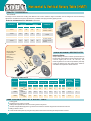
The worm gear is 1: 90.
One turn of the handle moves the table by 4"
Micro - collar is graduated in steps of 1 min.
Vernier scale makes settings down to 10 seconds possible
(20 seconds for 110242)
Dividing of 2 to 100 can be carried out quickly and accurately by attaching a Dividing Mechanism.
Center work can also be carried out by using the base in the vertical Position in conjunction with a tailstock.
THERE ARE THREE METHODS OF SETTING POSITIONS USING A ROTARY TABLE
1.
a
Use the degree scale on the outer edge of the table
(scale reading = 1 degree)
To use the degree scale on the table top, disengage the worm by unlocking the T screw and rotating the pin on the worm collar clockwise.
The table can be rotated by hand and can be locked in any position using the lock clamps.
2.
a
Use the degree handwheel (scale on handwheel = degrees and minutes)
To use the handwheel, unlock or loosen the T screw and rotate the pin on the worm collar anti-clockwise and when the worm has
engaged, lock or tighten the T screw. If the worm collar will not rotate easily, it may be necessary to rotate the handwheel while keeping
pressure on the pin so the worm will mesh or engage.
The hand wheel is divided into degrees and minutes eg: 4 degrees per revolution or ratio of 90:1. The minute divisions on the handwheel
can be further divided into 20 seconds using the vernier scale.
3.
a
Use the index method (use index plates and refer index table)
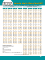
To use the index method first refer to the index table to select the index plate with the correct holes on the circle. (See Index table located
on the Page-6 back of this manual)
To use the index plates, the hand wheel must be removed by loosening the centre retaining screw and washer.
Mount the appropriate index plate with the correct number of holes to the collar with 3 screws.
Next fit the sector arms (the brass pieces) and adjust the sector arms for the correct number of holes. Holes are counted after the pin or
first hole. So for six holes, sector arms are actually set for seven holes ie; pin + 6 holes.
Fit the retaining washer in the groove in front of the sector arms.
Fit the crank with the spring loaded handle, adjusting so the plunger lines up with the correct circle of holes. Tighten with the screw and
washer that held the handwheel.
To index, rotate the handle the correct number of full turns anf then using the sector arms to measuer the number of holes. After the
handle is locked in, rotate the arms ready for the next cycle or index.
b
c
d
e
f
g
Eg: For 21 tooth gear or 21 divisions, Use the 21 hole plate. Set the sector arms for 6 holes then rotate the handle 4 full turns plus 6 holes.
If in doubt, have a practice run
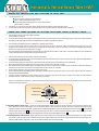
WORM SHAFT
SCREW A
MAIN BODY
WORM METAL
STEEL BALL
SCREW B
SHOWING SECTION
A
B
1. Adjusting Mesh of worm Gear:- Loosen the metal clamp handle and turn the switch metal clockwise until it touches the stopper. The
worm gear has now been disengaged. Turn it counterclockwise until it touches the stopper, the worm and gear wheel will engage.
Tighten the metal clamp handle after engagement. An additional adjustment can be obtained by removing the screw A and steel ball
and turning the inner screw B counter clock-wise so bringing the worm in closer engagement with the gear wheel. Turning clock-wise
brings the worm away from the wheel. After adjustment insert the steel ball and tighten screw A
2. Axial Adjustment of Worm shaft:- When axial slack occurs gear adjustment is carried out by tightening the inside worm shaft nut after
the handle, vernier ring and switch metal have been removed. After adjustment, lock the nut on the shaft by means of the set screw. (The
ROTARY TABLE has an adjustment, nut, which can be used after removal of the handle.)
2