1
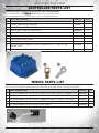
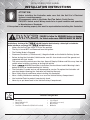
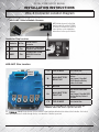
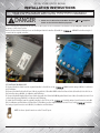
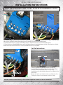
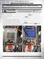
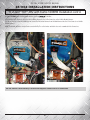
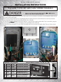
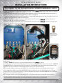
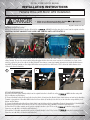
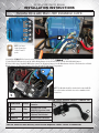
Distributed Exclusively by Madjax
600A 48V or 36V DC MOTOR CONTROLLER
Installation/Service Manual
25-001/07
600amp controller
25-002
on-the-fly programmer
25-003
wiring harness for CLUB CAR®
25-004
48v wiring harness for *E-Z-GO® TXT®
25-005
36v wiring harness for *E-Z-GO® TXT®
25-006
wiring harness for YAMAHA® Drive®
installation instructions
Instructions for:
Club Car® Precedent® & DS® with Curtis 1510/1515 Controller
*E-Z-GO® TXT® 48V with Curtis 1206HB Controller
*E-Z-GO® TXT® 36V with Curtis 1206MX Controller (Requires 36V Firmware)
Yamaha® Drive® with Moric Controller JW2
INSTA L LATI ON /SERVI C E MA N UA L
INTRODUCTION
600A 48V or 36V DC MOTOR CONTROLLER
The owner, and all vehicle operators MUST Read and Understand All Warnings and Instructions in this manual and in the Vehicle Owner/
Operator’s Manual. The owner of this vehicle assumes all liability for accidents, injuries or damages if the warnings and instructions are
not followed.
Madjax assumes no responsibility for errors or omissions in this manual, in regards to liability or damages resulting from the use of
information contained in the manual. If it is lost or damaged please contact your local dealer or Madjax.
Madjax reserves the right to make changes to the controller, parts of the controller, accessories, labeling or instructions without
obligation to make these changes on units previously sold.
Product and specifications are subject to change without notice or obligation.
ATTENTION:
BEFORE INSTALLING THIS CONTROLLER PLEASE RECORD THE SERIAL NUMBER LOCATED ON THE
BODY OF THE CONTROLLER.
PART
TORQUE 600AMP 48V DC CONTROLLER
TORQUE 600AMP 36V DC CONTROLLER
SERIAL #
*DISCLAIMER
*E-Z-Go , E-Z-Go TXT , and E-Z-Go RXV are registered trademarks of Textron Innovations, Inc. Club Car®, Club Car®
Precedent®, and Club Car® DS® are registered trademarks of Ingersoll Rand, Inc. Yamaha®, Yamaha® Drive®, G-14®, G-16®,
G-19®, and G-22® are registered trademarks of Yamaha Golf-Car Company. Any reference to Club Car®, E-Z-Go®, or
Yamaha® or their associated trademarks, word marks, and products are only for purposes of identifying golf carts with which
this Madjax® product is compatible. Madjax® products are aftermarket parts and are not original equipment parts. Madjax® is
not connected to, affiliated with, sponsored by, or endorsed by either Textron Innovations, Inc., Ingersoll Rand, Inc., Yamaha
Golf Cart Company, or any of their parent or subsidiary companies.
®
®
®
®
®
2
INSTA L LATI ON /SERVI C E MA N UA L
WARNINGS
SAFETY WARNINGS
MAKE SURE TO READ and UNDERSTAND the OWNER’S INSTALLATION and SERVICE MANUAL and ALL WARNING LABELS with
this Controller.
Make sure to also Read, Understand and follow the Vehicle’s OWNER’S MANUAL and ALL INSTRUCTIONS and WARNING
LABELS.
FAILURE to follow ALL WARNINGS AND INSTRUCTIONS can damage the Controller and /or the Vehicle and/or cause SERIOUS
INJURY OR DEATH!
• Do not leave children or pets unattended in or near the vehicle.
• Never drive too fast! The Terrain, conditions and the operator’s skill will determine a safe speed.
• Drive at a reduced speed and use extra caution when carrying passengers or cargo.
• Avoid sharp turns and do not accelerate quickly when turning.
• Always look behind you before and while backing up.
• Reduce speed when towing and allow more room for stopping and turning.
MOTOR KIT OPERATION
• Drive with wheels straight when going up and down hills.
• Slow down and use brakes when going down hills.
• Never
driveand
on hills
a slopekey
greater
than 15 degrees.
1. Insert
turnwith
vehicle
to Run.
• Do
drive
through
fast flowing
or water
floor of
vehicle.
2.not
Move
the
SilverWolf
Powerwater
Switch
fromabove
OFF the
to RUN
orthe
HIGH
depending on how much power is required.
• If you
mustThe
crossMotor
shallow
water, make
sure
to stopOn
andorinspect
area forofsudden
drop-offs, large rocks or slippery surfaces. Always
Note:
System
can be
turned
Off atthe
anytime
operation.
proceed with caution or choose a safer route.
3. ALWAYS look around the vehicle to make sure the area is clear before operating the vehicle!
• When towing this vehicle make sure the key is turned off, the Run/Tow switch is in Tow, and batteries main power is disconnected.
4. Move the SilverWolf Power Switch to the OFF position when the vehicle is not in use.
• Never exceed the towing capacity rating as specified by the vehicle manufacturer.
DANGER
• Keep electrical components dry and DO NOT wash with direct stream or power washer.
FAILURE to follow the WARNINGS below can damage
• Never re-wire, by-pass or change the wires, switches, or controller.
Contact
your dealer
or the
manufacturer
if vehicle
operating
the Vehicle
and/or
cause
SERIOUS
INJURY
ORis not
DEATH!
correctly.
• Keep the controller and the area around it clean and free of debris.
MAKE SURE TO READ and UNDERSTAND the OWNER’S INSTALLATION and SERVICE MANUAL and ALL WARNING
• LABELS
Vehicle and
all parts
must beKit.
serviced by qualified service personnel. For an authorized service location see your local dealer or visit
with
this Motor
our
web
site
at
www.silverwolfmotors.com.
call 1-866-410-5297
•
Always proceed with caution. KeepOrspeed
low and do not drive faster than conditions permit. The terrain,
conditions and the operator’s skill will determine a safe speed. Avoid sharp turns and do not accelerate quickly
when turning; this can cause the vehicle to slide sideways or skid out of control. Abrupt maneuvers or aggressive
driving can cause a rollover even on flat open areas.
•
DANGER
This Motor Kit will increase torque and traction; but this Does Not increase the GVWR (Gross Vehicle Weight
Rating), Cargo capacity or Towing capacity of the Vehicle. Always follow the Vehicle towing and loading
FAILURE to follow the WARNINGS below can damage
specifications.
cause
INJURY OR DEATH!
*This Label must be placed on the Vehicle in an areathe
thatVehicle
is in viewand/or
of the Driver
andSERIOUS
Passenger(s).
Part # PM00501
©2014 SilverWolf Vehicles Inc. Patents Pending.
MAKE SURE TO READ and UNDERSTAND the OWNER’S INSTALLATION and SERVICE MANUAL and
ALL WARNING LABELS with this Controller.
•
Always proceed with caution. Keep speed low and do not drive faster than conditions permit. The terrain, conditions and the
operator’s skill will determine a safe speed. Avoid sharp turns and do not accelerate quickly when turning; this can cause the vehicle
to slide sideways or skid out of control. Abrupt maneuvers or aggressive driving can cause a rollover even on flat open areas.
•
This Controller will increase torque, but Does Not increase the GVWR (Gross Vehicle Weight Rating), Cargo capacity or Towing
capacity of the Vehicle. Always follow the Vehicle towing and loading specifications.
3
INSTA L LATI ON /SERVI C E MA N UA L
CONTROLLER PARTS LIST
Confirm that all parts listed below are with your kit before starting installation.
This kit includes either the
600 AMP 48V Controller or the 36V Controller.
If you are missing parts please contact your local dealer or SilverWolf Vehicles Inc.
PART DESCRIPTION
PART #
QTY
1*
TORQUE 600 AMP 48V Controller
CDC648
1
1*
TORQUE 600 AMP 36V Controller
CDC636
1
2
M8 X 16 Hex Cap 8.8 Zinc (Not Shown)
80-000901
3
3
M6 X 16 Hex Cap 8.8 Zinc (Not Shown)
80-000902
2
4
M8 Lock Washer (Not Shown)
80-000910
3
5
M6 Lock Washer (Not Shown)
80-000909
2
6
M8 Flat Washer (Not Shown)
80-000888
3
7
M6 Flat Washer (Not Shown)
80-000889
2
8
Spade Connector 6.3MM (for Club Car Precedent & DS, *E-Z-GO TXT 36V
Yamaha Drive)
20-001010
2
9
2 AWG 5/16” Ring Terminal (Yamaha Drive Only!)
EW2G516
1
1
8
9
WIRING PARTS LIST
This kit includes only one of the Vehicle Module Harnesses listed below. Note: some Modules look similar. Make
sure to check the part number and description label on the bottom of the Module before connecting to the Controller.
PART DESCRIPTION
PART #
QTY
1*
MJ Vehicle Module Harness for Curtis 1510/1515 Controller (Club Car Precedent / DS)
W600100
1*
1*
MJ Vehicle Module Harness for Curtis 1206MX Controller (*E-Z-GO® *TXT® 36V)
W600200
1*
1*
MJ Vehicle Module Harness for Curtis 1206HB Controller (*E-Z-GO® *TXT® 48V)
W600201
1*
1*
MJ Vehicle Module Harness for Moric JW2 Controller(Yamaha Drive)
W600300
1*
1*
MJ Vehicle Module Harness for Curtis 1264, 1268ITS
W600400
1*
1*
NOTE: Club Car Precedent Vehicle Module Harness Shown
4
INSTA L LATI ON /SERVI C E MA N UA L
INSTALLATION INSTRUCTIONS
ATTENTION:
Before installing the Controller make sure that the Golf Car’s Electrical
System is working properly.
All components such as the Motor, Run/Tow Switch, Pedal Cluster,
FWD/REV Switch and all Wiring needs to be in good condition and operating
to Manufacturers Standards.
If the system is not working properly this must be repaired before installing this Controller!
DANGER
FAILURE to follow the WARNINGS below can damage
the Vehicle and/or cause SERIOUS INJURY OR DEATH!
Installation or Servicing of the
600 AMP Controller Must be done by a trained golf car technician.
Before installing or servicing of the
600 AMP Controller;
• Make sure the Run/Tow Switch is in the Tow position
• The Key is turned OFF and Removed from the Ignition
• The Parking Brake is Engaged
• Disconnect the Main (+) Positive and (-) Negative Cable on the Vehicle’s Battery System.
• Before testing the Controller/ Vehicle make sure ALL four wheels are off the ground and
supported with jack stands.
• The area around the vehicle must be clear. Keep all People, Children and Pets away from the
vehicle when installing, servicing or testing the vehicle.
• Read
600 AMP Controller Installation /Service Manual and All Warning Labels
before servicing or troubleshooting this Vehicle.
• The Controller is sealed and can not be opened for service. To replace the Controller call
your local dealer. Opening the Controller will Void the Warranty
• Wear Safety Glasses and Gloves when installing this Controller.
• Wear a Safety Shield when working in or near the Vehicle Battery Compartment.
• Use Insulated Tools to protect from electric shock.
• Never lay or put down tools in the Vehicle Battery Compartment.
Tools Required
•
•
•
•
Ratchet Set
Open End Wrench Set
Electrical Tape
Small Saw or Dremmel tool (Club Car Precedent)
•
•
•
•
5
4 Jack Stands
Lift Jack (2 ton or more)
Wheel Chocks
Multimeter
INSTA L LATI ON /SERVI C E MA N UA L
INSTALLATION INSTRUCTIONS
Wire & Connector Location Diagram
600 AMP Vehicle Module Harness
NOTE: Module shown is for the Club
Car Precedent, DS and the *E-Z-GO®
TXT® 48V, for Connector location for
other Vehicles see the installation
instructions for the specific Vehicle.
Connector Plug Location
Vehicle Harness
Connector
“On The Fly” Programmer
*(Optional) Not included
SilverWolf 4WD System
(WH03500 Extension
Cable)
1 Vehicle 16 Pin
2 OTF
8 Pin
3 4WD
3 Pin
2
1
3
600 AMP Wire Location
F1
STATUS
LIGHT
F2
B-
M
B+
F1
FIELD WIRE
Field Switch Wire
B-
MAIN BATTERY
NEGATIVE
BLACK Negative Cable from
Battery.
Also Connect SilverWolf
BLACK Negative Battery
Cables if installed.
M
MOTOR
B+
MAIN BATTERY
POSITIVE
RED Positive Cable from
Battery.
Also Connect SilverWolf RED
Positive Battery Cables if
installed.
F2
FIELD WIRE
Field Switch Wire
NOTE: F1 & F2 Field Wires if installed incorrectly the
FWD/REV Switch will work in opposite direction.
The
600 AMP Controller has a Green and Red Status Light that will indicate the status of the Controller. It is located
inside the controller and is visible through the top cover when the controller is powered.
6
MOTOR KIT OPERATION
1. Insert and turn vehicle key to Run.
INSTA L LATI ON /SERVI C E MA N UA L
2. Move the SilverWolf Power Switch from OFF to RUN or HIGH depending on how much power is required.
Note: The Motor System can be turned On or Off at anytime of operation.
INSTALLATION INSTRUCTIONS
3. ALWAYS look around the vehicle to make sure the area is clear before operating the vehicle!
Club Car Precedent with Curtis 1510/1515 Installation
4. Move the SilverWolf Power Switch to the OFF position when the vehicle is not in use.
DANGER
• Make sure the RUN/TOW Switch is in the TOW position.
FAILURE to follow the WARNINGS below can damage
Make
sure cause
to Disconnect
the Main
and Negative
the•Vehicle
and/or
SERIOUS INJURY
OR Positive
DEATH!
Cable on the Vehicle’s Battery System.
Before
the original
Controller take
note or take
a photo of the
Controller
Posts and
corresponding Wires. Make sure that
MAKEremoving
SURE TO READ
and UNDERSTAND
the OWNER’S
INSTALLATION
and5SERVICE
MANUAL
andtheir
ALL WARNING
allLABELS
groupswith
of wires
stay together.
this Motor
Kit.
Remove
(A) the
Vehicle
thedoOriginal
Controller.
Install
the
600 AMP Controller using the 3
•
Always
proceed
with Controller
caution. KeepCover
speed and
low and
not driveVehicle
faster than
conditions(B)
permit.
The terrain,
the operator’s
skill will determine a safe speed. Avoid sharp turns and do not accelerate quickly
screwsconditions
from theand
original
controller.
A•
when turning; this can cause the vehicle to slide sideways or skid out of control. Abrupt maneuvers or aggressive
driving can cause a rollover even on flat open areas.
B
This Motor Kit will increase torque and traction; but this Does Not increase the GVWR (Gross Vehicle Weight
Rating), Cargo capacity or Towing capacity of the Vehicle. Always follow the Vehicle towing and loading
specifications.
*This Label must be placed on the Vehicle in an area that is in view of the Driver and Passenger(s).
Part # PM00501
©2014 SilverWolf Vehicles Inc. Patents Pending.
SEE PHOTOS ON FOLLOWING PAGE
(C) Connect the Motor Cable from the original Controller to the M Post on the
600A Controller using a M8 Bolt, Lock Washer
and Flat Washer.
(D) Connect the Main Positive Red Power Cable along with the 2 SilverWolf 4WD Positive Red Power Cables (if installed) to the B+ Post on
the Controller using a M8 Bolt, Lock Washer and Flat Washer.
(E) Connect the Main Negative Black Power Cable along with the 2 SilverWolf 4WD Negative Black Power Cables (if installed) to the B- Post
on the Controller using a M8 Bolt, Lock Washer and Flat Washer.
(F) Install the F1 Field Wire from the original Controller to the F1 Post on the
Controller using a Spade Connector and a M6
Bolt, Lock Washer and Flat Washer. (G) Install the F2 Field Wire from the original Controller to the F2 Post on the
Controller
Post using a Spade Connector and a M6 Bolt, Lock Washer and Flat Washer.
NOTE: Use these Spade Connectors on the F2 and F1 posts.
7
INSTA L LATI ON /SERVI C E MA N UA L
INSTALLATION INSTRUCTIONS
Club Car Precedent with Curtis 1510/1515 Installation cont’d.
G
E
G
C
D
E
C
D
F
F
(H) Install the 25-003 20 Pin Connector on the Vehicle Module Harness to the
Controller. Note: The plastic around this plug
will need to be cut away to allow for the Body Cover to be re-installed. See the Cut Out instructions below.
(I) Install the 16 Pin Connector from the Vehicle Wiring Harness to the 16 Pin Connector on the Vehicle Module Harness.
(J) If the Vehicle has a SilverWolf 4WD System connect the Extension Harness from the Main Harness into the 3 Pin Connector on Vehicle
Module Harness.(K) This 8 Pin Connector is for the optional OTF “On The Fly” Programmer.
Cut Out Instructions
H
2”
5.5”
2.5”
.5”
J
K
I
If the Precedent has a six 8V Battery layout, the plastic on
Controller/Wiring Cover will need to be cut out to allow the 20 pin
Connector on the Vehicle Module Harness to fit properly.
Caution: Remove the Vehicle Module Harness before cutting in to the
plastic Cover.
Measure in from the outer right side of the cover 5.5” inches. Use a
2” wide piece of tape to cover and area 2” wide x 2.5” high.
Now the Vehicle’s Main Battery Positive and Negative Cables can be re-connected.
8
MOTOR INSTA
KITLOPERATION
LATI ON /SERVI C E MA N UA L
1. Insert and turn vehicle key to Run.
INSTALLATION INSTRUCTIONS
2. Move the SilverWolf Power Switch from OFF to RUN or HIGH depending on how much power is required.
Note: The Motor System can be turned On or Off at anytime of operation.
*E-Z-GO® 8TXT® 48V with Curtis 1206HB Installation
3. ALWAYS look around the vehicle to make sure the area is clear before operating the vehicle!
4. Move the SilverWolf Power Switch to the OFF position when the vehicle is not in use.
DANGER
• Make sure the RUN/TOW Switch is in the TOW position.
FAILURE to follow the WARNINGS below can damage
Make
sure cause
to Disconnect
the Main
and Negative
the•Vehicle
and/or
SERIOUS INJURY
OR Positive
DEATH!
Cable on the Vehicle’s Battery System.
Before
the original
Controller take
note or take
a photo of the
Controller
Posts and
corresponding Wires. Make sure that
MAKEremoving
SURE TO READ
and UNDERSTAND
the OWNER’S
INSTALLATION
and5SERVICE
MANUAL
andtheir
ALL WARNING
the
groups
of
wires
stay
together.
LABELS with this Motor Kit.
Remove
(A) the
Vehicle
thedoOriginal
Controller.
Install
the
600 AMP Controller using the 3
•
Always
proceed
with Controller
caution. KeepCover
speed and
low and
not driveVehicle
faster than
conditions(B)
permit.
The terrain,
conditions
and
the
operator’s
skill
will
determine
a
safe
speed.
Avoid
sharp
turns
and
do
not
accelerate
quickly
screws from the original controller.
when turning; this can cause the vehicle to slide sideways or skid out of control. Abrupt maneuvers or aggressive
(C) Connect
theflatoriginal
Controller to the M Post on the
600A Controller using a M8 Bolt, Lock Washer
drivingthe
can Motor
cause a Cable
rolloverfrom
even on
open areas.
and
Flat
Washer.
•
This Motor Kit will increase torque and traction; but this Does Not increase the GVWR (Gross Vehicle Weight
Rating),the
Cargo
capacity
or Towing
of the Vehicle.
Alwaysthe
follow
the Vehicle towing
and loading
(D) Connect
Main
Positive
Red capacity
Power Cable
along with
2 SilverWolf
4WD Positive
Red Power Cables (if installed) to the B+ Post on
specifications.
the Controller using a M8 Bolt, Lock Washer and Flat Washer.
Label must be placed on the Vehicle in an area that is in view of the Driver and Passenger(s).
(E) *This
Connect
the Main Negative Black Power Cable along with the 2 SilverWolf 4WD Negative Black Power Cables (if installed) to the B- Post
Part # PM00501
©2014 SilverWolf Vehicles Inc. Patents Pending.
on the Controller using a M8 Bolt, Lock Washer and Flat Washer.
(F) Install the F1 Field Wire from the original Controller to the F1 Post on the
Controller using a Spade Connector and a M6
Bolt, Lock Washer and Flat Washer. (G) Install the F2 Field Wire from the original Controller to the F2 Post on the
Controller
Post using a Spade Connector and a M6 Bolt, Lock Washer and Flat Washer.
B
A
G E
9
C D
F
INSTA L LATI ON /SERVI C E MA N UA L
25-004 INSTALLATION INSTRUCTIONS
*E-Z-GO® TXT® 48V with Curtis 1206HB Installation cont’d.
(G) Install 25-004 on the Vehicle Module Harness to the
Controller.
(H) Install the 16 Pin Connector from the Vehicle Wiring Harness to the 16 Pin Connector on the Vehicle Module Harness.
(I) If the Vehicle has a SilverWolf 4WD System connect the Extension Harness from the Main Harness into the 3 Pin Connector on Vehicle
Module Harness.
NOTE: The Module should be oriented and secured with Zip Ties so that water and debris does not accumulate in the Connectors.
G
H
I
Now the Vehicle’s Main Battery Positive and Negative Cables can be re-connected.
10
MOTOR KIT OPERATION
1. Insert and turn vehicle key to Run.
INSTA L LATI ON /SERVI C E MA N UA L
2. Move the SilverWolf Power Switch from OFF to RUN or HIGH depending on how much power is required.
Note: The Motor System can be turned On or Off at anytime of operation.
INSTALLATION INSTRUCTIONS
3. ALWAYS look around the vehicle to make sure the area is clear before operating the vehicle!
*E-Z-GO® *TXT® 36V with Curtis 1206MX Installation
4. Move the SilverWolf Power Switch to the OFF position when the vehicle is not in use.
DANGER
• Make sure the RUN/TOW Switch is in the TOW position.
FAILURE to follow the WARNINGS below can damage
Make
sure cause
to Disconnect
the Main
and Negative
the•Vehicle
and/or
SERIOUS INJURY
OR Positive
DEATH!
Cable on the Vehicle’s Battery System.
Before
the original
Controller take
note or take
a photo of the
Controller
Posts and
corresponding Wires. Make sure that
MAKEremoving
SURE TO READ
and UNDERSTAND
the OWNER’S
INSTALLATION
and5SERVICE
MANUAL
andtheir
ALL WARNING
the
groupswith
of wires
stay together.
LABELS
this Motor
Kit.
Remove
(A)
the
Vehicle
Controller
andand
thedoOriginal
Controller.
Solenoid Bracket from the Solenoid and the
•
Always proceed with caution. KeepCover
speed low
not driveVehicle
faster than
conditions Remove
permit. Thethe
terrain,
conditions
and thePlate.
operator’s
willSolenoid
determineBracket
a safe speed.
sharp
turns and do not accelerate quickly
Controller
Mounting
Note:skillThe
willAvoid
not be
re-installed.
when turning; this can cause the vehicle to slide sideways or skid out of control. Abrupt maneuvers or aggressive
(B) Install
thecan cause a rollover600
36V
Controller
using the 3 screws from the original controller. Note: These Screws will be going into
driving
evenAMP
on flat
open
areas.
non-threaded
the Screws
aretraction;
self tapping
Screws
willthe
make
their
own
threads.
•
This Motorholes
Kit willbut
increase
torque and
but this Does
Not and
increase
GVWR
(Gross
Vehicle
Weight
Rating),
capacity
or Towing
the Vehicle.
Always follow
the Vehicle
towing
loading
(C) Attach
theCargo
Solenoid
using
the 2capacity
Screwsoffrom
the Solenoid
Bracket
to the
areaand
below
the Controller. Note: There are 2 holes already
drilled.specifications.
*This Label must be placed on the Vehicle in an area that is in view of the Driver and Passenger(s).
A
©2014 SilverWolf Vehicles Inc. Patents Pending.
A
CPart # PM00501
B
Connector Plug Location
1
2
3
4
Vehicle
Vehicle
Vehicle
Vehicle
3 Pin
4 Pin
4 Pin
10 Pin
5 4WD
3 Pin
6 OTF
8 Pin
Vehicle Module Harness *E-Z-GO TXT 36V
Vehicle Harness Connector
Vehicle Harness Connector
5
Vehicle Harness Connector
1
2
Vehicle Harness Connector
SilverWolf 4WD System
6
(WH03500 Extension Cable)
“On The Fly” Programmer
3
4
*(Optional) Not included
11
INSTA L LATI ON /SERVI C E MA N UA L
INSTALLATION INSTRUCTIONS
*E-Z-GO® *TXT® 36V with Curtis 1206MX Installation cont’d.
(D) Connect the Motor Cable from the original Controller to the M Post on the
600A Controller using a M8 Bolt, Lock Washer
and Flat Washer.
(E) Connect the Main Positive Red Power Cable from the Vehicle Solenoid along with the 2 SilverWolf 4WD Positive Red Power Cables (if
installed) to the B+ Post on the Controller using a M8 Bolt, Lock Washer and Flat Washer.
(F) Connect the Main Negative Black Power Cable along with the 2 SilverWolf 4WD Negative Black Power Cables (if installed) to the B- Post
on the Controller using a M8 Bolt, Lock Washer and Flat Washer.
(G) Install the F1 Field Wire (usually green) from the original Controller to the F1 Post on the
Controller using a Spade
Connector and a M6 Bolt, Lock Washer and Flat Washer.
(H) Install the F2 Field Wire (usually black) from the original Controller to the F2 Post on the
Controller Post using a Spade
Connector and a M6 Bolt, Lock Washer and Flat Washer.
I
NOTE: Use these
Spade Connectors
on the F2 and F1
posts.
J
H
F
D
E G
2
1
4
3
See the “CONNECTOR PLUG LOCATION” Chart on the previous page and photo I above to connect the Vehicle Connectors to the Vehicle
Module Harness.
(I) Install the 25-005 20 Pin Connector on the Vehicle Module Harness to the
Controller.
(J) Install the Connectors from the Vehicle Wiring Harness to the Connectors on the Vehicle Module Harness as shown in the “CONNECTOR
PLUG LOCATION” Chart on the previous page. Note: If the Vehicle has a SilverWolf 4WD System connect the Extension Harness from the
Main Harness into the 3 Pin Connector on Vehicle Module Harness (Shown as # 5 on the previous page).
NOTE: The Module should be oriented and secured with Zip Ties so that water and debris does not accumulate in the Connectors.
(K) If re-installing the Controller Cover with the RUN/TOW Switch the Cover, will need to be cut off at the bottom because of the new
Solenoid location. Use a Saw to cut the bottom 2”’s of the Cover. Plug in the 4 pin Connector from the RUN/TOW Switch to the SW Vehicle
Module Harness and reinstall the Controller Cover.
NOTE: The Module should be oriented and secured with Zip Ties so that water and debris does not accumulate in the Connectors.
Now the Vehicle’s Main Battery Positive and Negative Cables can be re-connected.
12
MOTORINSTA
KITL LATI
OPERATION
ON /SERVI C E MA N UA L
1. Insert and turn vehicle key to Run.
INSTALLATION INSTRUCTIONS
2. Move the SilverWolf Power Switch from OFF to RUN or HIGH depending on how much power is required.
Note: The Motor System can be turned On or Off at anytime of operation.
Yamaha Drive with Moric JW2 Installation
3. ALWAYS look around the vehicle to make sure the area is clear before operating the vehicle!
4. Move the SilverWolf Power Switch to the OFF position when the vehicle is not in use.
DANGER
• Make sure the RUN/TOW Switch is in the TOW position.
FAILURE to follow the WARNINGS below can damage
Make
sure cause
to Disconnect
the Main
and Negative
the•Vehicle
and/or
SERIOUS INJURY
OR Positive
DEATH!
Cable on the Vehicle’s Battery System.
Before
the original
Controller take
note or take
a photo of the
Controller
Posts and
corresponding Wires. Make sure that
MAKEremoving
SURE TO READ
and UNDERSTAND
the OWNER’S
INSTALLATION
and5SERVICE
MANUAL
andtheir
ALL WARNING
the
groups
of
wires
stay
together.
LABELS with this Motor Kit.
Remove
(A) the Original Vehicle Controller. (B) Install the
600 AMP Controller using the 3 screws from the original controller.
•
Always proceed with caution. Keep speed low and do not drive faster than conditions permit. The terrain,
CAUTION:
NOT
CONNECT
ANY aWIRES
UNTIL
AFTER
STEP C.
conditionsDO
and the
operator’s
skill will determine
safe speed. OR
AvoidCABLES
sharp turns and
do not accelerate
quickly
when turning; this can cause the vehicle to slide sideways or skid out of control. Abrupt maneuvers or aggressive
driving can cause a rollover even on flat open areas.
A This Motor Kit will increase torque and traction; but this Does Not increase the GVWR
B (Gross Vehicle Weight
•
Rating), Cargo capacity or Towing capacity of the Vehicle. Always follow the Vehicle towing and loading
specifications.
*This Label must be placed on the Vehicle in an area that is in view of the Driver and Passenger(s).
Part # PM00501
©2014 SilverWolf Vehicles Inc. Patents Pending.
Locate (C) the Y cable on the Vehicle Harness: shown as A2 in the photo below. This cable consists of 2 cables crimped together in to
a Ring Terminal. The one side comes from the Battery Negative and the other side comes from the A2 on the Motor. Use a pair of side
cutters to cut the A2 side of the cable at the Ring Terminal. Then crimp on a new ring terminal (included in the Vehicle Module Harness
bag). NOTE: The Ring Terminals on the original Vehicle Harness may need to be drilled out to 5/16” to allow the Vehicle Harness to be
connected to the new Controller.
C
1
3
2
CUT
A2
B+
A2
A2
B-
SEE PHOTO ON FOLLOWING PAGE
(D) Connect the Motor Cable (usually white) from the original Controller to the M Post on the
600A Controller using a M8
Bolt, Lock Washer and Flat Washer.
(E) Connect the Main Positive Red Power Cable from the Vehicle Solenoid and the Black A2 Cable (Cable that was cut and has the New Ring
Terminal) along with the 2 SilverWolf 4WD Positive Red Power Cables (if installed) to the B+ Post on the Controller using a M8 Bolt, Lock
Washer and Flat Washer.
(F) Connect the Main Negative Black Power Cable (Cable from the Battery with the original Ring Terminal) along with the 2 SilverWolf 4WD
Negative Black Power Cables (if installed) to the B- Post on the Controller using a M8 Bolt, Lock Washer and Flat Washer.
(G) Install the F1 Field Wire (usually green) from the original Controller to the F1 Post on the
Controller using a Spade
Connector and a M6 Bolt, Lock Washer and Flat Washer.
(H) Install the F2 Field Wire (usually black) from the original Controller to the F2 Post on the
Controller Post using a Spade
Connector and a M6 Bolt, Lock Washer and Flat Washer.
13
INSTA L LATI ON /SERVI C E MA N UA L
INSTALLATION INSTRUCTIONS
F1
B+
E
D
F2
B-
G
M
Yamaha Drive with Moric JW2 Installation cont’d.
F
H
E
A2
G
E
D
F
NOTE: Use these
Spade Connectors
on the F2 and F1
posts.
H
(I) Install the 25-006 20 Pin Connector on the Vehicle Module Harness to the
Controller.
(J) Install the 26 PIN Connector from the Vehicle Wiring Harness to the 26 Pin Connector on the Vehicle Module Harness.
(K) If the Vehicle has a SilverWolf 4WD System connect the Extension Harness from the Main Harness into the 3 Pin Connector on Vehicle
Module Harness. (L) This 8 Pin Connector is for the optional OTF “On The Fly” Programmer.
I
K
J
NOTE: The Module should be oriented and secured with Zip
Ties so that water and debris does not accumulate in the
Connectors.
L
Connector Plug Location
1 Controller
2 4WD
3 OTF
4 Vehicle
25-006 Vehicle Module Harness (Yamaha DR.)
Harness
20 Pin Controller
Connector
SilverWolf 4WD System
3 Pin
(WH03500 Extension Cable)
“On The Fly” Programmer
8 Pin
*(Optional) Not included
26 Pin Vehicle Harness Connector
4
2
3
Now the Vehicle’s Main Battery Positive and Negative Cables can be re-connected.
14
1
INSTA L LATI ON /SERVI C E MA N UA L
25-002 INSTALLATION INSTRUCTIONS
OTF “On the Fly” Programmer (Optional)
DANGER
FAILURE to follow the WARNINGS below can damage
the Vehicle and/or cause SERIOUS INJURY OR DEATH!
Vehicle Module Harness
OTF 8 Pin Connector
PART #
25-002
Speed: Top speed / Low speed
Regeneration: Motor Braking (How the brakes react to the
depression of the accelerator)
Accel: Torque behind take off speed
To install The OTF “On the Fly” Programmer
• First make sure the Vehicle RUN/TOW Switch is in the TOW position and the Key is turned off.
• The OTF can be mounted on the Vehicle or removed and used as required for programming purposes.
• The OTF has a long enough Cable to allow it to be mounted to the Dash area. Make sure to run the Cable in an area where it can not
MOTOR
KIT OPERATION
get pinched,
damaged
or wet. i.e. Under the Floor Mat in the wiring channel. Use the Velcro provided to secure it to an open area on
1. Insert the
and turnDash.
vehicle key to Run.
the SilverWolf Power Switch from OFF to RUN or HIGH depending on how much power is required.
•2. Move
Plug
the end of the OTF in to the 8 Pin connector on the Vehicle Module Harness.
Note: The Motor System can be turned On or Off at anytime of operation.
3. ALWAYS look around the vehicle to make sure the area is clear before operating the vehicle!
4. Move the SilverWolf Power Switch to the OFF position when the vehicle is not in use.
The OTF has been set to Factory Settings. When changing the settings it must be done in small increments and tested in
DANGER
an open area away from people, pets or large objects.
FAILURE to follow the WARNINGS below can damage
the Vehicle and/or cause SERIOUS INJURY OR DEATH!
MAKE SURE TO READ and UNDERSTAND the OWNER’S INSTALLATION and SERVICE MANUAL and ALL WARNING
LABELS with this Motor Kit.
To program the desired settings into the controller:
• Turn the lock out key from the Lock to Unlock.
• Adjust Maximum Speed, Regen and Acceleration to desired settings.
• Turn the
key to Lock
in the setting and remove the key from programmer.
MOTOR
KIT OPERATION
NOTE:
Key
the operater to lock the settings on the Controller. Once the OTF is locked or unplugged from the Controller the
1. Insert andThe
turn vehicle
key toallows
Run.
2. Move the SilverWolf
Power
Switchbe
fromchanged.
OFF to RUN or HIGH depending on how much power is required.
settings
can
not
Note: The Motor System can be turned On or Off at anytime of operation.
•
•
Always proceed with caution. Keep speed low and do not drive faster than conditions permit. The terrain,
conditions and the operator’s skill will determine a safe speed. Avoid sharp turns and do not accelerate quickly
when turning; this can cause the vehicle to slide sideways or skid out of control. Abrupt maneuvers or aggressive
driving can cause a rollover even on flat open areas.
This Motor Kit will increase torque and traction; but this Does Not increase the GVWR (Gross Vehicle Weight
Rating), Cargo capacity or Towing capacity of the Vehicle. Always follow the Vehicle towing and loading
specifications.
*This Label must be placed on the Vehicle in an area that is in view of the Driver and Passenger(s).
Part # PM00501
©2014 SilverWolf Vehicles Inc. Patents Pending.
3. ALWAYS look around the vehicle to make sure the area is clear before operating the vehicle!
4. Move the SilverWolf Power Switch to the OFF position when the vehicle is not in use.
Make sure to remove the key and keep it in a safe and secure spot.
DANGER
FAILURE to follow the WARNINGS below can damage
the Vehicle and/or cause SERIOUS INJURY OR DEATH!
MAKE SURE TO READ and UNDERSTAND the OWNER’S INSTALLATION and SERVICE MANUAL and ALL WARNING
LABELS with this Motor Kit.
•
•
Always proceed with caution. Keep speed low and do not drive faster than conditions permit. The terrain,
conditions and the operator’s skill will determine a safe speed. Avoid sharp turns and do not accelerate quickly
when turning; this can cause the vehicle to slide sideways or skid out of control. Abrupt maneuvers or aggressive
driving can cause a rollover even on flat open areas.
This Motor Kit will increase torque and traction; but this Does Not increase the GVWR (Gross Vehicle Weight
Rating), Cargo capacity or Towing capacity of the Vehicle. Always follow the Vehicle towing and loading
specifications.
*This Label must be placed on the Vehicle in an area that is in view of the Driver and Passenger(s).
©2014 SilverWolf Vehicles Inc. Patents Pending.
15
Part # PM00501
INSTA L LATI ON /SERVI C E MA N UA L
INSTALLATION INSTRUCTIONS
MOTOR KIT OPERATION
1. Insert and turn vehicle key to Run.
Controller Pre-Drive Test:
2. Move the SilverWolf Power Switch from OFF to RUN or HIGH depending on how much power is required.
Note: The Motor System can be turned On or Off at anytime of operation.
3. ALWAYS look around the vehicle to make sure the area is clear before operating the vehicle!
4. Move the SilverWolf Power Switch to the OFF position when the vehicle is not in use.
DANGER
CAUTION:
MOTOR
KIT OPERATION All 4 Wheels MUST be off the ground!
FAILURE to follow the WARNINGS below can damage
the Vehicle and/or cause SERIOUS INJURY OR DEATH!
TO READ
the OWNER’S INSTALLATION and SERVICE MANUAL and ALL WARNING
1. Insert andMAKE
turnSURE
vehicle
keyand
toUNDERSTAND
Run.
LABELS with this Motor Kit.
1.2. MoveMove
the Run/Tow Switch to the Run position.
the SilverWolf Power Switch from OFF to RUN or HIGH depending on how much power is required.
Note:Insert
The Motor System and
can be turned
On or Off atKey
anytime of operation.
2.
turn
to ON
3. ALWAYS look around the vehicle to make sure the area is clear before operating the vehicle!
3.
Move
Vehicle’s
FNR
switch to the Forward position.
4. Move the SilverWolf Power Switch to the OFF position when the vehicle is not in use.
•
•
Always proceed with caution. Keep speed low and do not drive faster than conditions permit. The terrain,
conditions and the operator’s skill will determine a safe speed. Avoid sharp turns and do not accelerate quickly
when turning; this can cause the vehicle to slide sideways or skid out of control. Abrupt maneuvers or aggressive
driving can cause a rollover even on flat open areas.
This Motor Kit will increase torque and traction; but this Does Not increase the GVWR (Gross Vehicle Weight
Rating), Cargo capacity or Towing capacity of the Vehicle. Always follow the Vehicle towing and loading
specifications.
*This Label must be placed on the Vehicle in an area that is in view of the Driver and Passenger(s).
Caution: the F1 and F2 Wires could be reversed do to Vehicle Wiring and may cause the vehicle to
DANGER
move in the opposite direction as shown on the Switch.
©2014 SilverWolf Vehicles Inc. Patents Pending.
Part # PM00501
FAILURE to follow the WARNINGS below can damage
the Vehicle and/or cause SERIOUS INJURY OR DEATH!
MAKE SURE TO READ and UNDERSTAND the OWNER’S INSTALLATION and SERVICE MANUAL and ALL WARNING
LABELS with
this Motoron
Kit.
4.
Step
the Accelerator to test that the Vehicle is operating. Repeat this test with the switch in the
Reverse position.
•
•
Always proceed with caution. Keep speed low and do not drive faster than conditions permit. The terrain,
conditions and the operator’s skill will determine a safe speed. Avoid sharp turns and do not accelerate quickly
when turning; this can cause the vehicle to slide sideways or skid out of control. Abrupt maneuvers or aggressive
driving can cause a rollover even on flat open areas.
This Motor Kit will increase torque and traction; but this Does Not increase the GVWR (Gross Vehicle Weight
Rating), Cargo capacity or Towing capacity of the Vehicle. Always follow the Vehicle towing and loading
specifications.
*This Label must be placed on the Vehicle in an area that is in view of the Driver and Passenger(s).
Part # PM00501
If the Rear Wheels of the vehicle are not running properly during the Pre-Drive Test see the chart below to test the Vehicle Switches.
NOTE: On the OTF the LED will flash once when the Key, Forward, Reverse, or Foot Switch is activated and at 100%.
The following test procedures are to show that the Controller is getting the correct signals.
If a OTF Programmer was not purchased the Vehicles Reverse Buzzer will beep (if it is connected) and this can be used for the test
procedures.
©2014 SilverWolf Vehicles Inc. Patents Pending.
CONTROLLER INPUT SIGNAL CHECK
TEST
ACTION
RESULT
YES NO
1
Key Switch
Turn Key Switch to ON
1 Green Flash/ Beep
OK
Replace Key Switch
2
Forward
Move Switch to Forward
1 Green Flash/ Beep
OK
Replace FNR Switch
3
Reverse
Move Switch to Reverse
1 Green Flash/ Beep
OK
Replace FNR Switch
4
Foot Switch
Slowly depress the Accelerator
1 Green Flash/ Beep
OK
Replace Throttle Sensor/ or Throttle
5
100% Throttle
Continue to depress Accelerator to Floor.
1 Green Flash/ Beep
OK
Replace Throttle Sensor/ or Throttle
MOTOR KIT OPERATION
1. Insert and turn vehicle key to Run.
Controller Drive Test:
2. Move the SilverWolf Power Switch from OFF to RUN or HIGH depending on how much power is required.
Note: The Motor System can be turned On or Off at anytime of operation.
3. ALWAYS look around the vehicle to make sure the area is clear before operating the vehicle!
4. Move the SilverWolf Power Switch to the OFF position when the vehicle is not in use.
Caution: Before taking the Vehicle for the “Final Run Test” check for any loose wires or parts that could
DANGER
get caught or damaged.
FAILURE to follow the WARNINGS below can damage
the Vehicle and/or cause SERIOUS INJURY OR DEATH!
MAKE SURE TO READ and UNDERSTAND the OWNER’S INSTALLATION and SERVICE MANUAL and ALL WARNING
LABELS with this Motor Kit.
This test will show that the Controller is installed and running correctly.
•
Always proceed with caution. Keep speed low and do not drive faster than conditions permit. The terrain,
conditions and the operator’s skill will determine a safe speed. Avoid sharp turns and do not accelerate quickly
when turning; this can cause the vehicle to slide sideways or skid out of control. Abrupt maneuvers or aggressive
driving can cause a rollover even on flat open areas.
BEFORE YOU RUN THE FINAL TEST COMPLETE THE FOLLOWING STEPS:
•
This Motor Kit will increase torque and traction; but this Does Not increase the GVWR (Gross Vehicle Weight
Rating), Cargo capacity or Towing capacity of the Vehicle. Always follow the Vehicle towing and loading
specifications.
*This Label must be placed on the Vehicle in an area that is in view of the Driver and Passenger(s).
1.
Lift the Vehicle to allow the Jack Stands to be removed and the Vehicle to be lowered back to the ground.
2.Make sure the area around the Vehicle is clear; No people, children, pets, or objects that could come in contact with the Vehicle.
3.
Move the Run/Tow Switch to Run
4.
Turn the Key to Run and dis-engage the Parking Brake
5.
Drive the Vehicle to an open area. Slowly Accelerate allowing time to get use to the extra power.
©2014 SilverWolf Vehicles Inc. Patents Pending.
Part # PM00501
16
INSTA L LATI ON /SERVI C E MA N UA L
TROUBLESHOOTING
DANGER
•
•
•
•
Failure to follow the Warnings in this Manual can damage the Vehicle and/or cause SERIOUS INJURY OR
DEATH.
Service of the
600A Controller Must be done by a trained golf car technician.
Before troubleshooting the
600 AMP Controller;
Make sure the Run/Tow Switch is in the Tow position
The Key is turned OFF
Make sure ALL four wheels are off the ground and the vehicle is supported with jack stands.
The Controller is sealed and can not be opened for service. Opening the Controller will Void the
Warranty
PRELIMINARY TROUBLESHOOTING
Vehicle Module Harness Connector
Tools Required:
Digital Multimeter
PIN 10
This Connector is part of the Vehicle Module Harness that is attached to the Controller.
ISSUE
POSSIBLE CAUSES
Vehicle/ Controller does • RUN/TOW off.
not power up.
• Discharged/ Bad Batteries
• Wiring and Connectors
• Correct voltage at Controller
• Faulty SW Vehicle Module
Harness
HOW TO CHECK
•
•
•
•
RUN/TOW Switch in RUN position.
Check Battery Pack voltage (It needs to be at least 31V to power up)
Check All Wires for damage or loose connections.
Check that the pins are fully seated in the Connectors (by tugging
lightly on the individual wires) and that the Connectors are fully
seated and locked into place.
• Check the voltage at the Controller between B+ and B- (it should be
the pack voltage).
• Check the voltage between Pin 10 of the Vehicle Module Harness’s
20 Pin Connector and the B-. (it should be pack voltage).
• Replace SW Vehicle Module Harness
If there is pack voltage at the Controller between B+, Pin 10 and B- replace the Controller and
re-test.
FLASH CODE TROUBLESHOOTING
The MADJAX 600A Controller has both a Red and a Green LED Status Light that will indicate the status of the Controller. It is located inside
the Controller and is visible through the Top Cover when the Controller is powered. The vehicle’s reverse buzzer will also chirp the flash
code in the event of a fault.
Note: If the Optional “On the Fly” Programmer was purchased it is also equipped with a BLUE LED Status Light. This light will indicate the
same Flash Codes except they will be in Green only.
GREEN LED Status Light will repeatedly flash twice if the Key Switch is OFF indicating the Controller is in Standby Mode.
GREEN LED Status Light will be on solid if the Key Switch is ON
The vehicle is ready to operate if the Red LED Status Light is not flashing.
RED LED Status Light flashing see the Flash Code Chart Below
RED LED Status Light contains a 2 digit code;
The 1st digit will appear and then there will be a 1 second pause before the 2nd digit appears. There will be a 2 second pause before the
error code repeats itself.
ie. 1 flash followed by a 1 second pause then 2 flash indicates 1-2 the performance is limited because the Motor or Controller is Hot.
17
INSTA L LATI ON /SERVI C E MA N UA L
TSX V2 TROUBLESHOOTING
FLASH
CODES
1-1
FLASH CODE
MESSAGE
DESCRIPTION
SOLUTION
HOW TO CHECK
• Use a Battery Load Tester to verify Battery
condition after charging.
• Connect Volt Meter to Main
and
on the Batteries. (Use alligator clips).
Measure the voltage while driving to see if
the voltage drops.
• Attach Volt Meter to
and
on the
Controller if the voltage drops at the
Controller and not at the Battery then the
Solenoid may be bad.
Voltage
Issue:
Batteries
Batteries are empty or
too low.
• Recharge Batteries
1-1
Voltage
Issue:
Batteries
Batteries too full
• Batteries can not take a
• Use a Battery Load Tester to verify Battery
charge. Check the Batteries,
condition after charging.
one or more Batteries may
be bad.
1-1
Voltage
Issue:
Solenoid
(Contactor)
Damaged Solenoid or
loose Wiring
• Confirm the Solenoid is
working properly. Change
Solenoid if required.
1-2
Temperature Performance is limited
(Controller) because the Controller
is Hot.
• Let Vehicle cool off; system • Check the temperature of the Controller
is over worked.
with a non-contact temperature sensor.
1-3
Charger
Interlock
Charger is connected.
• Disconnect the Charger
before trying to move.
Vehicle Charging Port
may be wet
• Dry and clean the Charger
Port
On Board Computer
(OBC) is in sleep mode.
• Depress the throttle twice
to wake up OBC.
• Replace Charger port on
Vehicle
• Check for bad or damaged
Batteries.
• Check Battery Cables are
not loose or damaged.
• Check Solenoid
• Put Vehicle in neutral and listen for
the Solenoid to click when Throttle is
depressed. If Solenoid Clicks Solenoid
should be replaced.
• If Solenoid does NOT click measure the
voltage across the Small Terminals of the
Solenoid when the Throttle is depressed.
It should read the Battery voltage. If it
reads the Battery voltage the Solenoid is
bad. If it does not read the Battery voltage
check Vehicle Wiring.
1-4
Temperature Performance is limited
(Motor)
because the Motor is
Hot.
• Let Vehicle cool off; system • Check the temperature of the Motor with
is over worked.
a non-contact temperature sensor.
2-1
Switch Fault Both FWD & REV signal
came on at the same
time.
• Check and replace FWD &
REV Switch
18
• Check the FNR Switch. Does the Switch
feel the same when toggled from FWD to
Neutral to REV? If so check continuity of
the Switch.
INSTA L LATI ON /SERVI C E MA N UA L
TSX V2 TROUBLESHOOTING
FLASH
CODES
FLASH CODE
MESSAGE
DESCRIPTION
SOLUTION
HOW TO CHECK
• Check for loose Wires. If there is a Diode
across the Solenoid check that it is not
shorted.
• Test Solenoid by measuring resistance
across the Small Terminals of the
Solenoid. The resistance should be
greater than 48 OHMS.
2 - 2 Main
Solenoid
(Contactor)
Solenoid Coil takes too
much current.
• Check for loose Wires
or a short across Small
Terminals on the Solenoid.
Replace main Solenoid.
2 - 3 Motor
High field resistance
• Check the Motor Field Wires • Visually check the Motor Cables by
(F1 & F2) to ensure they are
following the Cables from the terminals
not loose or damaged.
on the Motor to the Controller.
• Motor may be damaged
• Measure Motor resistance; from F1 to F2
internally and need to be
on the Motor. It should be around 1 to 2
replaced.
Ohms. If greater than 2 Ohms, the Motor
has an issue and may need to be replaced.
2 - 4 Controller
Abnormally low voltnot
age on the Controller
pre-charging between B+ and B-.
• Clean and dry off the
Controller
• Visually check for debris or moisture on
Controller Terminals and Wires (There may
be a short across the B+ and B- posts).
• Check voltage
• Check the voltage between B+ and B- on
the Controller. It should equal the Battery
Pack Voltage.
• Check all Wires connected
to the Controller
• Check that the Wires are not damaged.
• Check that the B+ and Field Wires are not
shorted to the Frame or each other.
• Check that no accessories (Light Kits,
Stereos, etc.) are using the Frame as a
ground.
2 - 4 Controller
Cables /Controller
not
pre-charging
Test Cables at the Controller
2-5
Accelerator
The Accelerator signal
is out of range. This
can be caused by a
faulty connection or a
defective Accelerator
Assembly
• Check Accelerator Wires,
• Check Accelerator Wires and Connections.
Vehicle Module Harness and • Measure the voltage between the main
Accelerator
B- and Pin # 2 (center pin) on the 3 pin
4WD connector in the Vehicle Module
Harness. The Voltage should start near 0V
and move up to a maximum of 5V. If not
replace Throttle Sensor. i.e. MCOR, ITS, etc.
3-3
Internal
Internal Issue
Can NOT be serviced in the field. Return to dealer or contact SilverWolf Vehicles
19
• Remove all Cables except B- from the
Controller.
• Tape Cables so they do not touch each
other or the Vehicle Frame. Controller
Module Harness should remain plugged
into the Controller.
• Move Run/Tow Switch to Run, Turn on Key
Switch, depress the throttle. If 2-4 Flash
Code returns replace the Controller.
• Otherwise there is a Wiring problem.
Reconnect Wires one at a time (Turn off
RUN/TOW Switch each time) until 2-4 Flash
Code returns. This will indicate where the
Wiring issue is located.
INSTA L LATI ON /SERVI C E MA N UA L
TSX V2 TROUBLESHOOTING
NON-FLASH CODE TROUBLESHOOTING
NON-FLASH CODE ERRORS. Note: The list below shows some possible issues when the Controller does not show a Flash Code
Error. These issues are mainly related to the Vehicle. Always check the Manufacturers Service Manual.
ISSUE
CAUSE
HOW TO CHECK
The Vehicle is moving
slower than normal.
•
•
•
•
•
•
•
•
Batteries are discharged
Bad or damaged Motor
Faulty Speed Sensor
Faulty Throttle
• OTF programmer is locked
at low speed
Re-charge the Batteries
Check Motor
Unplug Speed Sensor
Raise the Vehicle so all wheels are off the ground. Depress Throttle
and look for green flash on OTF Programmer when the Throttle is
almost completely depressed.
• Connect the OTF Programmer, unlock it and adjust to desired speed.
Note: Lock OTF Programmer before removing it or the settings may
change.
Vehicle is shutting
down.
• Check Vehicle Wiring for
loose connections
• Check the OBC (On Board
Computer)
• Check the OBC by referring to the “OBC section” in the
manufacturers service manual.
Oscillations or bumpy
feel when driving.
• Motor compatibility
• Check that the Motor is on the
recommended Motors list
Vehicle feels sluggish
• Battery Cables are
after driving for a while.
undersized
• Upgrade the Power Cables to at least 4AWG.
Faulty Controller
• Use a Digital Multimeter set to Diode mode
• Remove all Wires and Cables on Controller
• Use “Controller Diode Test” Chart below to test the Controller
• Controller malfunction
CONTROLLER DIODE TEST
BLACK RED
VOLTAGE
LEAD
LEAD
B+
M
0.42V approx.
M
B-
0.42V approx.
F1
B-
0.48V approx.
F2
B-
0.48V approx.
B+
F1
0.48V approx.
B+
F2
0.48V approx.
OTF TROUBLESHOOTING
ISSUE
CAUSE
HOW TO CHECK
OTF Knobs do not
change the Controller
settings.
• OTF is Locked
• OTF Connector
•
• OTF Faulty
• Use Key to unlock
OTF to adjust Controller settings.
• Check that the 8 Pin Connector on the OTF is plugged in to the SW
Vehicle Module Harness
• Replace OTF or return for service.
Settings are not chang- • OTF not locking in new
ing
settings
• After adjusting the knobs to the desired settings, move the OTF Key
from the
UNLOCK to the
LOCK position. The
LOCK position
saves the current settings to the Controller. The OTF may now be
unplugged and removed from the Vehicle.
20
ACCESSORIES
OTF “ON THE FLY” PROGRAMMER
RECOMMENDED
FOR OPTIMAL
PERFORMANCE
PART #
25-002
•
•
•
•
Driver can adjust the Acceleration, Regeneration, and Top Speed of the vehicle in Real Time.
Valet Lockout allows the owner to set and key-lock the operating behavior of the vehicle.
Simple diagnostics
Easy for the dealer/operator to diagnose the most common vehicle issues (low battery voltage, defective throttle, bad
FWD/REV switch, faulty key switch, etc.)
• Plug and Play installation
• Speed adjustability On the Fly from 8 to 25 mph
21
Limited Warranty
Madjax, warrants that the products sold to Customer by Madjax will be free from defect in materials and workmanship for a period two years (24
months), from the date of manufacture of the product, subject to the terms and conditions in this Limited Warranty.
If, during the applicable warranty period, (i) Madjax is advised in writing as to a defect in a Navitas product; (ii) such product is returned to a receiving
point designated by Madjax; and (iii) an examination of such product discloses to Madjax’ reasonable satisfaction that such product is defective and
such defect was not caused by accident, abuse, neglect, alteration, improper installation, lightning damage, submersion, short circuits due to improper
handling, repair, improper testing or use contrary to any instruction issued by Madjax, Madjax will repair or replace the defective product at no cost to
Customer, except for transportation costs. Replacement shall mean furnishing the Customer with a new product equivalent to the defective product.
All defective products replaced by Madjax under this warranty shall become the property of Madjax and must be returned to Madjax properly packed to
prevent physical damage.
Madjax does not warrant that any product is suitable for use in any particular application. Customer shall be responsible for evaluating the
appropriateness of the use of any specific Madjax product for a particular application and shall specify such use at the time of the placement of any
order for a Madjax product. Madjax shall be entitled to rely exclusively upon such representation in furnishing any product to Customer.
Warranty Limitations
The foregoing warranty constitutes Madjax’ exclusive Liability and the exclusive remedy of Customer for any breach of or any other nonconformity of
the products covered by this warranty. This warranty is exclusive and in lieu of all other warranties. Madjax makes no warranty, expressed or implied or
statutory including, without limitation, any warranty of merchantability or fitness for a particular purpose.
No representative, employee, distributor or dealer of Madjax has the authority to make or imply any warranty, representation, promise or agreement,
which in any way varies the terms of this limited warranty.
The Madjax products sold to Customer are intended to be used only in the application specified by Customer to Madjax. Any other use renders the
Limited Warranty expressed herein and all implied warranties null & void and same are hereby excluded. Under no circumstances shall Madjax be liable
to Customer or any third party for consequential, incidental, indirect, exemplary, special or other damages whether in an action based on contract, tort
(including negligence) or any other legal theory, arising out of or related to the products sold to Customer, including but not limited to lost profits or
loss of business, even if Madjax is apprised of the likelihood of such damages occurring.
This limited warranty may not be changed, modified, limited or extended in scope except by a written agreement signed by Madjax and Customer.
Except as stated, any purported modification of this limited warranty shall be null and void.
2051 2nd AVE NE
Cairo, GA 39826
866-410-5297
www.mymadjax.com