1
INSTA L LATI ON /SERVI C E MA N UA L
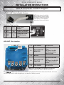
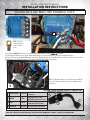
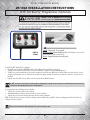
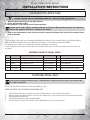
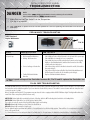
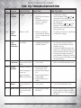
TSX V2 TROUBLESHOOTING
FLASH
CODES
FLASH CODE
MESSAGE
DESCRIPTION
SOLUTION
HOW TO CHECK
• Check for loose Wires. If there is a Diode
across the Solenoid check that it is not
shorted.
• Test Solenoid by measuring resistance
across the Small Terminals of the
Solenoid. The resistance should be
greater than 48 OHMS.
2 - 2 Main
Solenoid
(Contactor)
Solenoid Coil takes too
much current.
• Check for loose Wires
or a short across Small
Terminals on the Solenoid.
Replace main Solenoid.
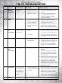
2 - 3 Motor
High field resistance
• Check the Motor Field Wires • Visually check the Motor Cables by
(F1 & F2) to ensure they are
following the Cables from the terminals
not loose or damaged.
on the Motor to the Controller.
• Motor may be damaged
• Measure Motor resistance; from F1 to F2
internally and need to be
on the Motor. It should be around 1 to 2
replaced.
Ohms. If greater than 2 Ohms, the Motor
has an issue and may need to be replaced.
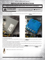
2 - 4 Controller
Abnormally low voltnot
age on the Controller
pre-charging between B+ and B-.
• Clean and dry off the
Controller
• Visually check for debris or moisture on
Controller Terminals and Wires (There may
be a short across the B+ and B- posts).
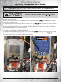
• Check voltage
• Check the voltage between B+ and B- on
the Controller. It should equal the Battery
Pack Voltage.
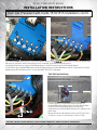
• Check all Wires connected
to the Controller
• Check that the Wires are not damaged.
• Check that the B+ and Field Wires are not
shorted to the Frame or each other.
• Check that no accessories (Light Kits,
Stereos, etc.) are using the Frame as a
ground.
2 - 4 Controller
Cables /Controller
not
pre-charging
Test Cables at the Controller
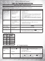
2-5
Accelerator
The Accelerator signal
is out of range. This
can be caused by a
faulty connection or a
defective Accelerator
Assembly
• Check Accelerator Wires,
• Check Accelerator Wires and Connections.
Vehicle Module Harness and • Measure the voltage between the main
Accelerator
B- and Pin # 2 (center pin) on the 3 pin
4WD connector in the Vehicle Module
Harness. The Voltage should start near 0V
and move up to a maximum of 5V. If not
replace Throttle Sensor. i.e. MCOR, ITS, etc.
3-3
Internal
Internal Issue
Can NOT be serviced in the field. Return to dealer or contact SilverWolf Vehicles
19
• Remove all Cables except B- from the
Controller.
• Tape Cables so they do not touch each
other or the Vehicle Frame. Controller
Module Harness should remain plugged
into the Controller.
• Move Run/Tow Switch to Run, Turn on Key
Switch, depress the throttle. If 2-4 Flash
Code returns replace the Controller.
• Otherwise there is a Wiring problem.
Reconnect Wires one at a time (Turn off
RUN/TOW Switch each time) until 2-4 Flash
Code returns. This will indicate where the
Wiring issue is located.