1
V
%
OPERATING AND
i
+
SERVICE MANUAL
Model 468-DC
t
Satellite Synchronized Clock
-4
Y
'F.
9
t
7
%
F
%
s
r&
?
%&P
TRUE TIME DIVISION, 3243 SANTA ROSA AVE., SANTA ROSA, CA95401, PHONE (707) 528-1230
-
SECTION I
GENERAL INFORMATION
1-1
INTRODUCTION
1-2
This manual has been designed and written to provide
the owner of the Model 468-DC "GOES" Satellite Synchronized Clock
with all the data and information needed to operate and u t f 3 3 z ~
all its features.
1-3
The information included in this manual is as complete
as possible and includes normal maintenance and adjustment data
that may be required to facilitate field repair of the unit.
The Model 468-DC has been designed to receive the NOAA
1-4
"GOES" Satellite which transmits on a frequency of 468 MHz and
decode the time information from the broadcasts as well as display outputs for supplying the time information to other equipment. The Synchronized Clock inits standard configuration
provides a front panel display of days, hours, minutes, and seconds
with five rear panel BNC connectors with IRIG B, lHz, 1 kHz,
Precision 60 Hz, and Slow Code locked to the electrically
outputted time (and options if ordered), may be in either Universal
Coordinated Time (UTC), more comonly referred to as Greenwich
Mean Time (GMT), or in local time. This is done through the proper
time zone offset selected by the rear panel thumbwheel switches.
The Model 468-DC is shipped to display the time of year in the
twenty-four hour format. By simply removing the cover and switching
the position of the small switch on the microprocessor circuit
board, the unit can be converted to display and output time in
the more conventional twelve hour format.
1-5
This instrument has been designed to be completely automatic requiring only antenna installation and connection of the unit
to the power source. Once the instrument is installed and turned
on, the microprocessor will lock to the signal from the "GOES"
Satellite (either East or West Satellite by sweeping for lock),
decode and display the time. From that point on, the unit will
require no further attention and will provide time to an accuracy
of +1.0 ms, continually updated by and phase locked to the transmissions of the "GOES" Satellite. In the event of loss of signal,
the unit will continue operation on its internal crystal time base.
If power should fail, upon restoration, the unit will again read
the time signals and start displaying the time transmitted.
1-6
The Model 468-DC Synchronized Digital Clock is guaranteed
to operate at any location within the 7O viewing angle of the
satellite as shown on the map enclosed.
OF STDS
UENT CO.
WARRANTY
TRUE TIME INSTRUMENTS warrants each instrument
i t manufactures t o be free from d e f e o t s i n i t s material
and workmanship for a period o f tuo years from t h e date
o f d e l i v e r y . Under t h i s warranty any instrument which
i s returned t o us ( f r e i g h t pre-paid) and i s found by
us t o be d e f e c t i v e i n material o r workmanship w i l l be
repaired o r replace ( a t our option) and returned a t no
charge t o the customer.
Our o b l i g a t i o n under t h i s warranty i s l i m i t e d t o
semic*ing o r adju$tment of any i n s t m e n t returned.
Items not covered by t h i s warranty are: fuses, b a t t e r i e s ,
and any illuminated parts o r damage caused by accident
or physical destruction o f the instrument.
This warranty i s expressly i n l i e u o f a l l other
obligations or l i a b i l i t i e s on the part o f TRUE TIME
S T R U T S . TRUE TIME INSTRUMENTS n e i t h e r assumes nor
authorizes any other person t o asswne for them any other
l i a b i l i t y i n connection h t h owl sales.
This warranty i s applicable i n the United S t a t e s and
Canada only. For other arkas, consult "KINEMETRICS, INC. "
1-8
SPECIFICATIONS
R E C E I V E R FREQUENCY:
468.8250 and 468.8375 MHz Automatic or
Manual select.
SYSTEM S E N S I T I V I T Y :
The sensitivity is suitable for proper
o eration with satellite viewing angle
78 or more above the horizon. When using
the A-468MS Antenna. (-.ZPV/m)
SYSTEM N O I S E MARGIN:
Operates with 9db attenuator inserted
between A-468MS flat plate and preamp
input in locations which have a Satellite
elevation of greater than 15O.
T I M I N G ACCURACY:
1)
+1.5 ms of UTC/NBS Time when corrected
For propagation delay through on board
switches and using the A-468MS Antenna.
2)
The time difference between neighboring
clocks locked to the same satellite is
considerably improved over UTC timing
accuracy. Consult the factory for
specification and conditions.
P R O P A G A T ION D E L A Y
CORRECTION:
T I M E BASE S T A B I L I T Y :
Two internal decade switches provide +50
ms
correction capability in 1 ms steps.
When not phase locked, crystal controls to
+6
- x
For higher stability time base when not
phase locked to satellite, see "External
Oscillator Input" Option.
k" high planar gas discharge. Displays
DISPLAY:
day of year, hours, minutes and seconds.
D I S P L A Y ACCURACY:
-0 to +lo0 ms, anytime colons are not
flashing.
N O M I N A L TURN-ON
Three minutes from power on and signal
reception with 90% confidence under average
signal conditions.
OPERATING TEMP:
TIME:
o0
to 50'
C.
REAR P A N E L O U T P U T S :
Rising edge on time, drives ten TTL loads
or CMOS. High lo%, Low 90%. See Section
3-24.
Rising edge on time, drives two TTL loads
or CMOS. High lo%, Low 90%. See Section
3-26.
'
REMOTE DISPLAY
DRIVING (IRIG B):
IRIG B Time Code is provided on a rear
panel BNC connector. Standard IRIG B Time
Code is an amplitude modulated lkHz carrier.
This output can also be easily field converted to TTL compatable D.C. level shift
time code. See Section 3-28.
SLOW CODE:
BNC output of 1 pulse per minute (lppm),
1 pulse per hour (lpph), and 1 pulse per
day (lppd). The pulses go high on time
and remain high for 2 seconds for minute
mark, 4 seconds for hour mark and 6 seconds
for day mark. Capable of sourcing 40 MA
at 4.0 volts minimum, and pulled to ground
by a lknresistor. See Section 3-36.
60 HZ:
Provided on BNC connector as frequency
source to drive a synchronous motor
through a power amplifier. Capable of
sourcing 100ua @ 2.4V and sinking 1.6 MA
@ .4V. (TTL Load).
The output square wave
has an unusual duty cycle. The 60 Hz is a
50% duty cycle over 50 ms (3 cycles).
Cycle $11
Cycle $12
Cycle $13
High 9ms, Low 8ms
High 8ms, Low 9ms
High 8ms, Low 8ms
See Section 3-41.
.
EXTERNAL
OSCILLATOR (OPT.): Input level of less than 4V and greater
than 2.4 volts (TTL) sine wave or square
wave is required. Any frequency from 100
kHz to lOmHz in multiples of lookHz is satisfactory. No unit adjustment is needed
regardless of frequency. Used as clock timebase when not phase locked to the satellite.
See Section 3-45.
IRIG H (OPTION):
PARALLEL BCD
TIME (OPTION)
:
BNC output of standard IRIG H format TTL
DC level shift supplied unless otherwise
requested. If lkHz amplitude modulated
carrier requested, IRIG B will automatically
be supplied in D.C. Level Shift format.
See Section 3-52.
If ordered, Parallel BCD time of year is
provided on rear panel 50 pin "D" connector.
Days, hours, minutes, seconds and milliseconds are provided. Lines indicating
worst-case time error of +I, +5, +50 and
+500ms drives 2 standard w
~ loads
~
~
or w
wC~OS". See Section 3-56.
RS-232 (OPTION):
The displayed time of year is outputted
in EIA Standard RS-232C configuration via
a "Motorola ACIA". Output format is
D D D H H M M S S and an indicator of the
time quality, CR/LF. Baud Rate and "ACIA"
options are dip switch selectable.
See Section 3-67.
IEEE-488 (OPTION):
IEEE Buss interface is also available. The
time is outputted in ASCII format, with the
most significant digit first (100's of days).
Among operating modes is time on demand to
the millisecond level, or marked time to
the milliseconds level. See Section 3-99.
HOURS O F F S E T :
Rear panel thumbwheel switch allows adjustment of + or - "0" to "11" hours from
transmitted UTC time.
12/24-HR.
Dip Switch located inside unit allows use
as 12 hour clock in place of 24 hour format
as shipped.
468-DC
OPERATION:
S Y N C H R O N I Z E D D I G I T A L CLOCK
SIZE:
1-314" x 17" x lot.;" (4.4 x 43.2 x 26.7cm)
behind panel. Mounts in standard 19"
(48.9cm) EIA rack system, hardware included.
24" (60.9) hardware available.
WEIGHT:
7& lbs. (3.5kg) Ship Wt. 12 lbs. (5.4kg).
POWER:
95-135VAC, 60-400Hz, less than 25 volt
amps. Others available on request.
A-468MS
ANTENNA
SIZE:
12" x 12" x 7%" high (30.5cm x 30.5cm x 19.5cm)
provided with universal mounting and hardware.
9-3/4 lbs. (4.4kg) Ship Wt. 13 lbs. (5.9kg).
WE I GHT:
A-468HX ANTENNA
SIZE:
12" x 12" x 3 ' 6" high (30.5cm x 30.5cm
x 196.6cm) provided with a universal
mounting system and hardware.,
WEIGHT:
14% lbs. (6.5kg)
2 0 *.,
Ship Wt. 19 lbs, (8.6kg).
I
i ..,.
E
H,:&?1 " "
\
<
A
D*
N 6.S TIME
TRUE ?,ME OIWISIOW
Y O D l l d l 8 OC
r
i
\r
INSTALLATION
2-1
ANTENNA
INSTALLATION
2-2
The Model 468-DC Synchronized Clock is shipped ready for
operation and will require no adjustments. The first step in set-up
and operation of the unit is to install the antenna included with
the unit. An antenna supplied by True Time for use with the Model
468-DC must be used in conjunction with this receiver/clock as the
antenna includes not only a preamp, but receiver controlled frequency conversion circuits. The use of "in antenna conversion"
of the 468 MHz frequency to a lower frequency for transmission
down the coax allows up to 1000 feet of RG-58/U lead in coax to be
used.
2-3
Since the Model 468-DC can be used to automatically switch
from one satellite to the other (EAST or WEST) the user must first
determine if the unit is to be allowed to automatically select
either satellite or to be locked to either the East or the West
satellite. If the propagation delay must be calculated and preset
on the internal switches to obtain the ultimate unit accuracy with
respect to another 468-DC in the field or with respect to the transmitted time, it will be required to lock the clock onto one satellite.
If only basic time is required and a change in received satellite
which might result in a worst case error in propagation delay of 9 ms.
is acceptable, the advantage of automatic scanning of the satellites
can be maintained. This scanning allows the receiver to select
either receivable satellite in the case of poor or no reception from
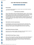
one. A second consideration is if the user is within the reception
range of one or both satellites, and if a common pointing direction
will be suitable for reception of both satellites. This can be
evaluated by the use of the pointing angle maps, figure 2-1 and 2-2.
The beamwidth of the A-468MS antenna is approximately 90°.
2-4
Once it is determined which satellite will be received (or
if both are to be received) the attached maps can be used to determine
the besting pointing direction for the users location. In the case
of the A-468MS, the antenna should be physically pointed such that the
signal from the satellite comes onto the antenna receiving plate
through the top of the plastic bubble. The axis of the A-468HX, the
Helix should be pointed at the satellite for best results. Thus, if
the user was directly under the satellite, the antenna would be set
with it facing straight up. If the satellite was at a '7 angle above
the horizon, the antenna must be tipped at 83O.
2-5
Included with the antenna is a mounting flange with a shaft
attached to allow versatile tipping as well as rotation for proper
antenna pointing. The stand also allows attachment of this antenna
to a flat surface for mounting. See SECTION VI.
LONGITUDE
100
120
140
160
E
180
W
160
140
120
100
80
60
40
LONGITUDE
EASTERN S A T E L L I T E P O I N T I N G ANGLES.
20
0
20
40
LONG ITUDE
1
120
140
160
E
180
W
160
140
120
100
80
60
40
LONG ITUDE
WESTERN S A T E L L I T E P O I N T I N G ANGLES.
20
0
20
40
2-6
Once the mounting and pointing of the antenna is complete,
attach a lead in coax. For this purpose RG-58/U is available from
True Time at 50' and 100' lengths.
2-7
RACK MOUNTING
2-8
If it is desired to mount the Model 468-DC in a standard
19" rack system, use the rack mounting ears provided with the unit.
These ears may be attached to the side of the cabinet by removing
the two 8-32 flat head screws on the side of the instrument and
placing the screws through the counter-sunk hole in the bracket and
re-installing the screw. The unit now may be mounted in a 1-314"
opening in any EIA Standard 19" rack system.
2-9
INSTRUMENT START-UP
2-10
After the antenna installation is complete, as described in
SECTION 2-2 above, the lead-in coax should be connected to the rear
panel BNC connector labeled "ANTENNA". Connect the power cord to
the socket on the rear panel and plug the unit into an appropriate
power source. The power switch on the front panel may now be turned
on.
2-11
When the power is turned on, the initial indication of
proper operation of the Model 468-DC is the colons on the display.
The colons will blink off and on at about once per second. This
indicates to the user that the unit is operating properly and that
the receiver is looking for phase lock to the carrier of the signal
and then to the 100 Hz data rate of the information broadcast. Next,
after the 468-DC has read and recognized the maximum length sequence
(MLS) transmitted each 4 second, the colons will be locked on solid.
2-12
Following this data lock, the synchronized clock will recognize that it is reading data, a satellite location (as transmitted in
the message) will be read. From this information, the 468-DC can
determine if it is locked to the "EAST" or "WEST" Satellite and light
the appropriate "LED" on the front panel.
2-13
Finally, after two 30 second long time frames of information of the time of year have been read which agree as to the time,
the front panel display will light indicating the correct time of
year. At this same time, any options which have been ordered to
electrically output the time will begin to function.
2-14
One of the most often overlooked and yet most important
factors in the installation and o eration of the Model 468-DC is
proper antenna installation. Wit out a proper antenna installation,
the signal from the satellite will not be received and thus the unit
cannot possible function properly. In many cases "just to try it
out", an attempt will be made to operate the unit without determining
the proper antenna pointing or inside of the building. This, as
often as not, results in inability to lock to the satellite signal,
and failure to decode the time.
!
SECTICN 111
OPERATION
INTRODUCTION
3- 2
The Model 468-DC Synchronized Clock prc~vkdes t h e ~ r s e r
with a means of obtaining time traceable to t h e U.S. NatianaE 3ureau
of Standards with an accuracy of +1.5 ms. For stability, the time
base is phase-locked to the satelTite data rate. The time of year
information broadcast by the National Oceanic and Atmospheric
Administration through the "GOES" Satellite is displayed in days,
hours, minutes and seconds on the front panel. Also available are
outputs of this time information in the form of Remote Display Driving
Output (IRIG B, Parallel BCD Time, or RS-232C compatable interface,
or IEEE-488 compatability). The Model 468-DC has been specifically
designed to minimize operator set-up and will provide many years of
service without attention.
3-3
SATELLITE
EAST-WEST LED
3-4
Located on the lower left hand corner of the front panel
are two LED'S labeled "Satellite", "WEST" or "EAST". These green
LEDs will light any time the unit is receiving a sufficient signal
from one of the satellites to allow the internal time base to phase
lock to the data frequency of 100Hz. When the unit is initially
turned on, if adequate signal is present, this LED will light within
30 to 45 seconds. If during the course of operation phase lock with
the satellite is lost long enough for the R.F. Circuits to sweep for
phase lock, (about 150 seconds), this light will go out. When phase
lock is regained and a satellite position is recognized in the data,
the appropriate LED will again light.
3-5
Phase lock will be maintained continually in most areas
and the only occasion for loss of lock will be experienced due to
local noise interference. The most common source is "land mobile"
transmitters on a frequency of 468.8250 MHz which is directly on
the Western Satellite frequency.
3-6
The Satellite LED also provides information as to the
Satellite position. If the 468-DC is able to read the time of year
information but the satellite position information read in code does
not agree with the position shown on the propagation determination
maps, (Figure 3-2 and 3-3), the LED will blink. If the R.F. carrier
02 which the time data was found is on the 468.8250 MHz frequency,
the West LED will blink, if on 468.8375 MHz, the East Led will blink.
This indicates to the user which Satellite is being received, but that
~aopagatiandelay information may be incorrect and exact satellite
position should be determined Ef accuracies to the millisecond level
a r c desired. Satellite LED blinking also occur when the unit is in
'bA~tomatic"
sstellit-e selection, the 465 DC has swept to the other
tllite, but complete iime synchronizati~nis not complete. This
* , l l y requires less t h ~ n15 minutes to aecomp!ish and then clears
blinking.
3-7
DISPLAY
3-8
The front panel display of time is blanked when the unit
is initially turned on, because the correct time is not known. The
time information broadcast by the "GOES" Satellite is repeated every
30 seconds. The time information is broadcast in the first 11 seconds
of each % minute. Requirements for the display to light are: 1) the
unit must obtain phase lock with the carrier of satellite, 2) phase
lock with the lOOHz data rate must be obtained, and 3) two consecutive
frames of time code must be read which agree as to the time. When
these 3 criteria are met, the display will light showing the correct
time in days, hours, minutes and seconds, Universal Coordinated time
(UTC) more commonly referred to as Greenwich Mean time (GMT).
Correction to local time, conversion to a 12-hour clock in place of
the 24-hour time base as transmitted and correction for propagation
delay are covered in the following sections.
The display has been designed to indicate to the user the
3-9
accuracy of the time information being displayed and on the time output
lines if ordered. After the display turns on, it will indicate the
worst case accumulated drift of the time information should phase lock
with the satellite be lost. When the unit has accumulated loss of
lock for 2% hours since the last synchronization to +5ms., the colons
will flash. The flashing colons indicate that the estimate of the
worst-case error of the display and outputted time is +50ms. of
N.B.S. time. When the unit has been in operation for Fifteen hours
without phase lock since the last synchronization, the complete
display will flash. This flashing is certain to attract the operators
attention and indicates that thz time as displayed and outputted may
have a worst case error of more than +500 ms. (4, seconds).
3-10
Display or colon flashing will stop when the signal from
the satellite is regained, phase locked to and the time code is
read. Under normal operation, this will occur without operator
attention. It is very unlikely that either of these conditicns will
occur under normal conditions. Due to the abili~yof the unit to
phase lock to the carrier frequency down to very low signal levels,
persistant flashing of the colons or display may be an indication of
poor reception due to local interference or antenna location and/or
installation. Refer to SECTION V "Maintenance and Troubleshooting"
for additional information on this subject .
3-11
HOURS O F F S E T
3-12
Located on the rear panel is a thumbwheel switch labeled
"HOURS OFFSET". This switch is set for "0" at the factory which means
that the displayed time will be Coordinated Universal Time as broadcast.
To change the hours on the display to read local time, set the switch
to the number of hours your lccation is offset from Greenwich, England.
For example, if you are located in the Eastern Time Zone and desire to
display Local Standard Time, the switch should be set for "-5", or for
Daylight Savings Time s e t f o r "-4".
I f , i n t h i s case, the display
was i n d i c a t i n g 1800 UTC, t h e c l o c k would s u b t r a c t 5 hours and d i s p l a y
1300 hours f o r Local Standard Time. I f t h e u n i t has e l e c t r i c a l l y o u t p u t t e d time, (IRIG B, P a r a l l e l BCD, RS-232 o r IEEE-488) t h e time
s u p p l i e d on t h e s e o u t p u t s w i l l a g r e e with t h e d i s p l a y . Additonal
i n f o r m a t i o n on t h e s e o u t p u t s i s i n c l u d e d i n t h e f o l l o w i n g s e c t i o n s .
3- 13
12/24-HOUR
CLOCK O P E R A T I O N
3- 14
The Model 468-DC i s shipped from t h e f a c t o r y f o r o p e r a t i o n
on t h e 24-hour c l o c k system a s b r o a d c a s t by t h e National Bureau of
S t a n d a r d s . I f it i s d e s i r e d t o c o n v e r t t h e c l o c k t o a 12-hour c l o c k
d i s p l a y , a small i n t e r n a l s w i t c h can be t u r n e d .
3- 15
To c o n v e r t a c l o c k t o t h e 12-hour format r e f e r t o F i g u r e
3-1. Remove t h e f o u r screws r e t a i n i n g t h e l i d and s l i d e t h e s w i t c h
i n d i c a t e d i n t h e photograph t o t h e 12-hour p o s i t i o n .
Replace t h e
cover and r e i n s t a l l t h e screws.
3- 16
AUTOMATIC/MANUAL
SATELLITE SELECTION
3-17
As d e s c r i b e d i n S e c t i o n 2-3, t h e Model 468-DC can be used
t o a u t o m a t i c a l l y s e l e c t t h e "EAST" o r the "WEST" s a t e l l i t e , o r can be
s e t manually f o r l o c k t o e i t h e r s a t e l l i t e . The r e c e i v e r , a s shipped
from t h e f a c t o r y i s s e t f o r "Automatic" scanning of t h e s a t e l l i t e s .
I f i t i s d e s i r e d t o l o c k t h e r e c e i v e r onto e i t h e r s a t e l l i t e . remove
t h e f o u r screws r e t a i n i n g t h e l i d . By r e f e r r i n g t o F i g u r e 3-1, l o c a t e
t h e "EAST" and "WEST" S a t e l l i t e Switch. I f i t i s d e s i r e d t o l o c k
i f t h e "WEST"
t o t h e East S a t e l l i t e , t u r n t h e "EAST" Switch "ON"
With both
S a t e l l i t e i s d e s i r e d , t u r n t h e "WEST" Switch t o "oh".
switches "OFF" t h e u n i t w i l l be r e t u r n e d t o automatic scanning operation.
3- 18
PROPAGATION DELAY
3- 19
This f e a t u r e i s included with t h e Model 468-DC t o a l l o w
the microprocessor t o compensate f o r t h e d e l a y i n t h e d i s p l a y e d and
o u t p u t t e d time and timing marks due t o t h e time r e q u i r e d f o r t h e
s i g n a l t o t r a v e l t o t h e r e c e i v e r from t h e t r a n s m i t t e r .
3-20
This f e a t u r e c o n s i s t s of two switches on t h e D i g i t a l Board
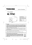
Assembly. To a d j u s t t h e s e s w i t c h e s , f i r s t remove t h e f o u r screws which
hold t h e t o p cover i n p l a c e , remove t h e l i d and s e t i t a s i d e . Refer
t o F i g u r e 3-1 f o r i d e n t i f i c a t i o n of t h e "Prop. Delay Switches".
The
two switches can be combined t o provide f o r a t o t a l of 99 ms, propagat i o n delay f o r t h e u n i t . The s w i t c h toward t h e r e a r panel p r o v i d e s
0 t o 9 ms. and t h e s w i t c h toward t h e f r o n adds t o t h i s i n s t e p s of t e n
from 0 t o 90 ms. T h e r e f o r e , i f i t i s d e s i r e d t o compensate f o r 59 ms.
propagation d e l a y , t h e f r o n t switch would be t u r n e d t o 5 ( f o r 50 ms)
and t h e r e a r s w i t c h t o 9 ( f o r 9 ms).
R F UNLOCK I N D I C A T O R
(RED LED)
l O O H z UNLOCK
l ND l CATOR (RED L E D ) Y
f
I R I G - B T T L / A M S E L E C T JUMPER
PROPROGATION DELAY SWITCHES
0sd'l ~'j;d;f
OR
l ND l CATOR (GREEN LED)
\- WEST S A T E L L I T E
SELECT SWITCH
FIGURE 3-1
PARTS LOCATION - MODEL 468-DC
LONG I TUDE
100
120
1hO
160
E
180
W
160
1hO
120
100
80
60
40
20
0
20
40
100
120
140
160
E
180
W
160
140
120
100
80
60
40
20
0
20
40
LONG I TUDE
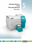
F I G U R E 3-2
WESTERN S A T E L L I T E MEAN DELAYS.
LATITUDE
18
3-2 1
Through the ground station at Wallops Island, the National
Bureau of Standards advances the time sent to the satellite by
260.000 ms. Propagation delay from Wallops Island to the Satellite
and back to earth varies between 242.50 and 271.50 ms. depending on
satellite position and the receiving location. This results in the
receiver signal being advanced up to 17.50 ms. or retarded by 11.50 ms
relative to UTC-NBS depending on receiver location and satellite
being received.
3-22
This offset can be conpensated for by the propagation
delay switches described above. A switch setting of 50 as shipped
from the factory, sets the output time of the synchronized clock
simultaneous with the received time of the signal. Increasing the
propagation delay switch setting advances the output time relative to
the received time by 1.0 ms per step. Thus, a switch setting of 62
advances the time output by 12 ms. as a setting of 32 on the switches
retards the output time by 18 ms.
3-23
The appropriate setting of the propagation delay switches
can be determined by the use of the attached maps, Figure 3-2 and
3-3. If the clock is locked to the "EAST" or "WEST" satellite as
described in SECTION 3-16, the delay can be determined relatively
accurately. If the unit is left on the "automatic" mode, the best
compromise must be determined depending on the receiver location.
EXAMPLE :
1)
A user located in the southern tip of Florida, USA
and having his unit locked to the "EAST" satellite
should set the switches to read 36 ms, "3" on the
10's of milliseconds switch and "6" on the units
of millisecond switch.
2)
If a unit is located at 120' West longitude and 40°
north latitude and left in "automatic" mode, the
switches should be set to read 46 or 47 milliseconds
at the users option. This would be obtained by
setting the 10's of milliseconds switch to "4" and
the units switch to "6" or "7".
3-25
The 1 Hz is provided as a rear panel BNC connector and can
be used for a wide variety of timing functions. This output is a
pulse going high as the second remains high for 100 milliseconds and
going low for the remaining 900 milliseconds. This output is driven
from a 2N3904 (43) on the microprocessor board (Assy. 86-42, see
SECTION V )
The collector of 43 is pulled up to +5VDC with a 3.3K
n resistor. This output is taken off of pin /I3 of assembly 86-42 and
capable of driving 10 TTL loads.
3-27
The lkHz rear panel output is similar in form to the 1Hz
above. It is a square wave going high on timesremaining high for 100
microseconds and low the remaining 900 microseconds. This output is
driven by U23 on assembly 86-74 (See SECTION V ) which is a CMOS
part number 4050. This output is fed to assembly 86-42 in interconnecting wire(s) and to the rear panel from 86-42 pin number 17
I R I G B-(REMOTE
D I S P L A Y D R I V I N G OUTPUT)
3-29
The primary purpose of the IRIG B time code output is to
drive slave displays manufactured by True Time Instruments. This
output consists of the standard IRIG B time code. Refer to SECTION VII
for a full description of this code.
3-30
When using this code for other than driving the True Time
Model RD-By it should be noted that four "Control Functions" are used.
These control functions encode estimated time accuracy as fully
described in SECTION VII
3-31
This output is supplied on a rear panel BNC connector.
When shipped, this output is in a lkHz carrier amplitude modulated
format but can be field converted to D.C. level shift code format.
In addition to driving remote displays, this output can be used to
synchronize commercially available Time Code Generators or direct
recording on magnetic tape.
3-32
The modulated 1 kHz format is a sine wave driven by two
sections of a Texas Instrument part number "TL084" in series with
50n located on assembly 86-74. The high level of the code is 3.3
volt peak to peak +.5V, at the low level it is 1 Volt peak to peak
+.2V. This output is then fed to assembly 86-42 via the jumber
wire (pin number "P") and to the rear panel from terminal number 18.
3-33
If it is desired to convert the IRIG B Time Code from the
amplitude modulated lkHz form as shipped, to a level shift output,
it is necessary to remove the lid and move one wire. To remove the
lid, take out the four screws in the cover and set the lid aside.
L>cate the Analog Board, Assembly 86-74 which can be identified with
tne assistance of the photograph in Figure 3-1 of this manual.
3-34
After locating the Analog Board, Assembly 86-74, note on
the right side of the board near the edge of a red jumper wire has
been installed in two of three holes in a triangular shape pattern.
the rear point to which the wire is soldered, labeled "AM", should be
unsoldered ans swung forward and resoldered into the hold, labeled
"TTL" toward the front of the instrument. This connects the lead
from the 2N3904 transistor near this hole to pin "P" of the edge
connector. Replace the lid and the IRIG B output will now be in
level shift format.
3- 35
The
assembly 86-74
10 TTL l o a d s .
assembly 86-42
nector via pin
Level S h i f t format i s d r i v e n by Q l O O (2N3904) on
w i t h 2 . 2 K n p u l l up t o +5VDC. T h i s w i l l d r i v e a b o u t
A f t e r l e a v i n g 4100, t h e I R I G B i s t r a n s f e r r e d t o
on jumper w i r e p i n "P" and t o t h e r e a r p a n e l con18 on t h i s assembly.
SLOW CODE
3- 37
The "Slow Code" o u t p u t from t h e Model 468-DC h a s been
p r o v i d e d p r i m a r i l y f o r t h e purpose o f p r o v i d i n g t i m i n g marks on
drum r e c o r d e r s such a s t h e K i n e m e t r i c s I n c . Model V R - 1 .
This output
i s a s i n g l e l i n e which goes h i g h once p e r m i n u t e . On minute marks
t h e o u t p u t remains h i g h f o r two s e c o n d s , on hour marks t h e l i n e i s
h e l d h i g h f o r 4 s e c o n d s and f o r t h e day mark, a s i x second h i g h i s
provided.
3- 38
T h i s o u t p u t i s d r i v e n by Q 1 on assembly 86-42. T h i s i s
a ME'S3702 t r a n s i s t o r and w i l l s o u r c e 4 0 m a . a t 4 . 0 VDC.
This d r i v e
i s p r o v i d e d from p i n {I2 on t h e assembly 86-42 t h r o u g h a w i r e t o t h e
r e a r p a n e l BNC.
3- 39
A second format o f t h i s slow code i s p r o v i d e d and can be
' 2 o f assembly 86-42
e a s i l y f i e l d c o n v e r t e d . I f t h e w i r e from p i n 71
i s connected t o p i n 111 on t h e assembly, t h e complement o f p i n {I2
d e s c r i b e d above i s p r o v i d e d . (See F i g u r e 3 - 1 ) .
P i n 111 o u t p u t i s
d r i v e n by 42 (2N3904) w i t h a p p r o x i m a t e l y 6K n p u l l up t o 5VDC. T h i s
w i l l d r i v e 2 TTL l o a d s . When w i r e d i n t h i s manner, t h e o u t p u t on
t h e r e a r p a n e l BNC w i l l be normally h i g h . On t h e minute i t w i l l go
low 2 s e c o n d s , 4 seconds on t h e hour and 6 seconds f o r a day
indicator.
3-40
NOTE:
I f "External O s c i l l a t o r " option i s ordered i n
c o n j u n c t i o n w i t h P a r a l l e l BCD, RS-232 o r IEEE-488 o u t p u t o p t i o n s ,
t h e "Slow Code" o u t p u t i s n o t on a r e a r p a n e l c o n n e c t o r b u t t h e u s e r
i s f r e e t o l i f t t h e l i d and o b t a i n t h i s o u t p u t from p i n 111 o r #2 o f
assembly 86-42 f o r u s e .
3-42
The p r e c i s i o n 60 H z o u t p u t on t h e r e a r p a n e l BNC, l i k e
t h e Slow Code, h a s been p r o v i d e d p r i m a r i l y f o r t h e purpose o f
s u p p l y i n g a known 60 H z s i g n a l t o d r i v e synchronous m o t o r s . T h i s
o u t p u t , when s u p p l i e d t h r o u g h a power a m p l i f i e r such a s t h e K i n e m e t r i c s
Model PA-1, w i l l p r o v i d e a c o n s t a n t 60 H z s i g n a l f o r d r i v i n g drum
r e c o r d e r s independent o f l o c a l power l i n e v a r i a t i o n s .
A q u a s i - s q u a r e wave i s p r o v i d e d f o r t h i s . p u r p o s e w i t h
3-43
t r a n s i t i o n s on e x a c t m i l l i s e c o n d s . The h a l f c y c l e p e r i o d s a r e 8ms,
8ms, 9ms, 8ms, 8ms and 9ms, e t c . , t h e n r e p e a t i n g t h e p a t t e r n . T h i s
p r o v i d e s e x a c t l y a 60 H z s q u a r e wave a f t e r t h e a v e r a g e o f t h r e e
cycles.
3-44
Driven by UI1 on assembly 86-42 (74LS00) t h i s o u t p u t i s
c a p a b l e o f d r i v i n g 5 TTL l o a d s . The o u t p u t i s from t h e f r o n t edge
o f assembly 86-42 from a b i f u r c a t e d t e r m i n a l l a b e l e d "60 Hz", through
a wire t o t h e r e a r panel connector.
3- 45
EXTERNAL OSCILLATOR
( S p e c i a l Order O p t i o n )
3- 46
I f optionally ordered, t h i s r e a r panel input provides f o r
a l o c a l l a b standard type of o s c i l l a t o r t o be u t i l i z e d a s a clock
time b a s e d u r i n g p e r i o d s when phase l o c k w i t h t h e s a t e l l i t e i s l o s t .
3-47
The i n p u t f r e q u e n c y f o r t h i s o p t i o n may be anywhere
between lOOkHz and lOOMHz i n i n c r e m e n t s o f 100kHz. The s i g n a l c a n
be a s i n e wave o r s q u a r e wave w i t h t h e low l e v e l l e s s t h a n .4V and
t h e peak g r e a t e r t h a n 2 . 4 (TTL). T h i s i n p u t i s p r e s e n t e d from t h e
r e a r p a n e l BNC t h r o u g h a coax t o an i n p u t o f U7 (74LS74) which h a s
a l O K n p u l l up t o +5VDC. T h i s i n p u t t h e r e f o r e i s one TTL l o a d .
3-48
O p e r a t i o n a l l y , anytime t h e Model 468-DC i s u n a b l e t o
phase l o c k t o t h e 100 Hz d a t a r a t e from t h e s a t e l l i t e , t h e c l o c k
time base w i l l u t i l i z e t h e p r o v i d e d i n p u t i n t h e " E x t e r n a l O s c i l l a t o r "
BNC c o n n e c t o r .
I f f r e q u e n c y i s n o t p r o v i d e d on t h i s BNC, t h e 468-DC
w i l l c o n t i n u e t o o p e r a t e on i t s own i n t e r n a l c r y s t a l .
3- 49
On Assembly 56-74, a g r e e n LED h a s been p r o v i d e d (See
F i g u r e 3-1) t o show t h e u s e r t h a t t h e 468-DC r e c o g n i z e s t h e p r e s e n c e
o f h i s e x t e r n a l o s c i l l a t o r . I f t h e LED i s n o t l i t , t h e u n i t does
n o t r e c o g n i z e t h e i n p u t s i g n a l and f u r t h e r i n v e s t i g a t i o n w i l l be
necessary f o r proper operation of t h i s option.
3- 50
When t h e s i t u a t i o n a r i s e s t h a t l o c k t o t h e s a t e l l i t e i s
l o s t , even i f a cesium o s c i l l a t o r i s used f o r t h e e x t e r n a l o s c i l l a t o r ,
t h e i n d i c a t i o n s o f time d r i f t c o n t i n u e . T h e r e f o r e , t h e c o l o n s on
t h e d i s p l a y and whole d i s p l a y w i l l b l a n k and f l a s h i n t h e u s u a l
manner t o i n d i c a t e l o s s o f s a t e l l i t e r e c e p t i o n even i n c a s e o f a
" p e r f e c t " e x t e r n a l time b a s e . The o u t p u t t i m e e r r o r message i n
I R I G B, P a r a l l e l BCD, RS-232 and IEEE-488 a l s o f u n c t i o n t o i n d i c a t e
l o s s of accuracy.
3- 5 1
IRIG H
( S v e c i a Z Order O v t i o n )
3-52
When o r d e r e d , I R I G H i s p r o v i d e d on a r e a r p a n e l BNC.
I f t h i s i s o r d e r e d i n c o n j u n c t i o n w i t h P a r a l l e l BCD o r RS-232 o r
IEEE-488, t h e 1Hz d e s c r i b e d i n S e c t i o n 3-24 i s d e l e t e d i n f a v o r o f
t h i s o u t p u t . The 1Hz i s a v a i l a b l e on asseinbly 86-42 a s d e s c r i b e d
b u t i s n o t on a r e a r p a n e l c o n n e c t o r . The u s e r c a n e a s i l y open t h e
t h e l i d and o b t a i n t h i s 1Hz i f d e s i r e d .
3-53
The format o f t h e I R I G H time code i s c o v e r e d i n S e c t i o n V I I
3-54
As shipped from the factory, the IRIG H Code is in D.C.
Level Shift format. This output is provided through a 2N3904 (on
Assembly 86-42) with a 3.3K n pull up to +5VDC. On request, this
output can be supplied as a lkHz amplitude modulated carrier. In
this case, the IRIG B will be supplied as DC level shift (See Section
3-35). The lkHz generations and modulation system, originally used
for the IRIG B (Section 3-32), will then be used for the IRIG H,
providing a lkHz carrier amplitude modulated in IRIG H format as
described in SECTION 3-32.
3-55
PARALLEL
BCD T I M E OUTPUT ( S p e c i a l O r d e r O ~ t i o n )
3-56
The Parallel BCD Time Output option is designed to
synchronize other equipment at the time provided by the National
Bureau of Standards. This output consists of 42 lines of BCD data
from 100's of days to units of milliseconds as shown in FISUBE 3-4.
Also, included with this option are four lines to indicate the
worst case error on the time outputted. One line indicates error
of more than +500ms, +50ms, +5ms and one indicated +lms. A 1Hz and
lkHz are available on-the output connector which can be used to
indicate to the user when the BCD time data on the lines are changing
states. If this option is included, a 50 pin "D" connector has been
installed on the rear panel.
3-57
All of the 42 BCD lines are driven by {/CD4050B's and are
capable of driving two TTL loads or multiple CMOS loads. These lines
are high to indicate a one in that position in the BCD code. For
further information regarding the output of these lines and their
capabilities, refer to SECTION V.
3-58
The pin of each output is shown in FIGURE 3-4 on the
following page.
3-59
During normal operation, after start-up and synchronization
with the Satellite, the four time quality lines will be in a low
state. When phase lock with the transmitter is lost, the Model
468-DC will provide the user with a worst-case estimate of the accumulated clock drift based on the VCXO drift rate. This estimate is
provided by each of the four lines changing to the high state in
turn as the clock time base drifts from synchronization with N.B.S.
When the time could be worse than +l.Oms the output on pin {I50 will
go high, at +5. Oms. Pin {I14 will go high and on through pin {I17 for
worse than +0.5, second accuracy. Each of these lines is driven by
a RCA {ICD4050 and is capable of driving two TTL loads or multiple
CMOS loads. It will be noted that when the +50ms line goes high, the
colons on the display will flash and when the +500ms
line goes high,
the complete display will flash.
When phase lock is regained, the lines will again go low
3-60
as the unit re-corrects to the proper time. On initial turn-on of
OUTPUT DATA
PIN
/I
OUTPUT DATA
2's
1's
8's
4's
2's
1's
4's
2's
1's
8's
4's
2's
1's
4's
2's
1's
of
of
of
of
of
~f
of
of
of
of
of
of
of
of
of
of
1 0 ' s of
1 0 ' s of
hrs.
hrs.
hrs.
hrs.
2 0 ' s of
1 0 ' s of
10's of
minutes
minutes
minutes
minutes
10's of
1 0 ' s of
1 0 ' s of
PIN
/I
OUTPUT DATA
8 ' s of seconds
4 ' s o f seconds
2 ' s of seconds
1 ' s o f seconds
8 ' s o f 1 0 0 ' s M-sec.
4 ' s of 1 0 0 ' s M-sec.
2 ' s of 1 0 0 ' s M-sec.
1 ' s o f 1 0 0 ' s M-sec.
8 ' s o f 1 0 ' s o f M-sec.
4 ' s o f 1 0 ' s of M-sec.
2 ' s of 1 0 ' s o f M-sec.
1 ' s of 1 0 ' s of M-sec.
8 ' s of u n i t s of M-sec.
4 ' s o f u n i t s of M-sec.
2 ' s o f u n i t s of M-sec.
1 ' s o f u n i t s of M-sec.
+l .Oms. (See Note 3il)
-
hrs.
hrs.
17
GROUND
I R I G B T i m e Code
2 ' s of 1 0 0 ' s o f days
1 ' s of 1 0 0 ' s o f days
8 ' s of 1 0 ' s of days
4 ' s of 1 0 ' s o f days
2 ' s of 1 0 ' s of days'
1 ' s of 1 0 ' s of d a y s
1 kHz
8 ' s of u n i t s of days
4 ' s o f u n i t s of days
2 ' s of u n i t s of days
1 ' s of u n i t s of days
+5ms. (See Note il3)
+50ms. (See Note il3)
1 Hz
+500ms.
(See Note il3)
-
NOTES :
1)
Mating Connector TRW ilDD-50s o r e q u i v a l e n t .
2)
Time a c c u r a c y l i n e s i n h i g h s t a t e i n d i c a t e s time a c c u r a c y worse t h a n l e v e l s p e c i f i e d .
FIGURE 3-4
-
P I N OUT CONFIGURATION
-
mins.
mins.
mins.
sec.
sec.
sec.
PARALLEL BCD TIME DATA
-
MODEL 468-DC
4
hl
t h e instrument o r a f t e r a power f a i l u r e , t h e +500ms l i n e w i l l remain
i n t h e high s t a t e u n t i l t h e d i s p l a y i s t u r n e d on, t h u s i n d i c a t i n g
t h a t t h e time on t h e p a r a l l e l o u t p u t l i n e s i s n o t c o r r e c t t o t h e
accuracy i n d i c a t e d by t h e o t h e r l i n e s , r e g a r d l e s s of t h e i r s t a t e .
This l i n e can t h e r e f o r e be used a s a r e a d - i n h i b i t l i n e s i n c e t h e
d a t a should n o t be r e a d when when t h i s l i n e i s i n t h e high s t a t e .
Refer to. t h e 1 Hz and 1 kHz d e s c r i p t i o n below f o r a d d i t i o n a l p a r a meters on r e a d i n g t h e time of t h e P a r a l l e l Output o p t i o n .
3-61
The 1 Hz o u t p u t l i n e on P i n {I16 i s d r i v e n by a {/CD4050B
and i s capable of d r i v i n g two TTL l o a d s o r m u l t i p l e CMOS l o a d s .
This l i n e goes t o t h e high s t a t e on time and remains high f o r 900ms.
A t any time t h e 1 Hz l i n e i s h i g h , t h e d a t a on t h e p a r a l l e l o u t p u t
l i n e s from t h e seconds l e v e l up i s n o t changing s t a t e s and i s
available f o r reading.
3-62
I f it i s desired t o read the milliseconds l i n e s a s well
a s t h e seconds through days, t h e 1 kHz l i n e should be u t i l i z e d a s
an i n d i c a t o r t h a t t h e l i n e s a r e n o t changing s t a t e s . The 8 0 0 ' s
of m i l l i s e c o n d s down t o 1 ' s of m i l l i s e c o n d s a r e d r i v e n by synchronous c o u n t e r s and may be changing s t a t e s d u r i n g t h e f i r s t &
microsecond of any m i l l i s e c o n d .
3-63
The lkHz l i n e i s d r i v e n by a {/CD4049B and i s capable of
d r i v i n g two TTL l o a d s o r m u l t i p l e CMOS l o a d s . The 1 kHz o u t p u t can
provide i n f o r m a t i o n t o t h e u s e r i n two f o r m a t s . The f i r s t format
i s a s shipped from t h e f a c t o r y . The second o u t p u t format can be
converted t o i n t h e f i e l d by two simple i n t e r n a l m o d i f i c a t i o n s .
3-64
As s u p p l i e d from t h e f a c t o r y , t h e 1 kHz o u t p u t on p i n 119
of t h e "D" connector goes h i g h on t h e m i l l i s e c o n d f o r 500 microseconds and t h e n goes low f o r L t h e remaining 500 microseconds. Since
t h e s t a t e of t h e P a r a l l e l Output Time d a t a may be changing s t a t e
during t h e f i r s t
microsecond of any m i l l i s e c o n d , t h e t r a n s i t i o n
from t h e low t o t h e h i g h s t a t e has been delayed t o a l l o w t h e m i l l i seconds counter t o s t a b i l i z e . The r i s i n g edge of t h e 1 kHz s i g n a l
may be used a s a Data S t r o b e . I f , r a t h e r t h a n one p o i n t i n time,
a time p e r i o d - o f w h e n i t i s "OK" t o read i s d e s i r e d , t h e time
p e r i o d s t a r t i n g a t t h e r i s e i n l e v e l of t h e 1 kHz l i n e and c o n t i n u i n g
f o r t h e next 500 microseconds can be u s e d . This 1 kHz l i n e should
be used i n c o n j u n c t i o n w i t h t h e +500ms l i n e a s d e s c r i b e d above t o
determine i f t h e time d a t a i s c o r r e c t and r e a d a b l e .
3-65
The second format f o r t h e 1 kHz o u t p u t l i n e w i l l p r o v i d e
an o u t p u t which w i l l go t o t h e high s t a t e approximately 3 . 0 microseconds b e f o r e t h e m i l l i s e c o n d and low 2 microseconds l a t e r . This
l i n e w i l l n o t go t o t h e low s t a t e i f t h e e s t i m a t e d time e r r o r of t h e
instrument i s worse t h a n +500ms and w i l l a l s o s t a y i n t h e high s t a t e
a f t e r i n i t i a l turn-on u n t i l t h e d a t a on t h e p a r a l l e l o u t p u t l i n e s
a r e c o r r e c t . This l i n e , t h e r e f o r e , p r o v i d e s one l i n e which, when i n
t h e low s t a t e i n d i c a t e s t h a t t h e time d a t a i s "OK" t o r e a d . To
convert the Model 468-DC to this configuration on the 1 kHz line,
remove the bottom cover of the instrument and locate assembly 86-44.
For identification of this Assembly and its parts, see FIGURE 3-5
of this manual. Locate the jumper wires (looks like a % watt
resistor with one black band) labeled JPR3. Unsolder the end
connected to the hole labeled "A" and solder it into the hole labeled
"B". Unsolder the jumper marked JPR2 and remove it from the board.
In the place of JPR2, solder in a 33k n resistor (t watt +5% carbon
resistor preferred). Replace the cover and the screws, tFe conversion is now complete.
F I R S T F O R M A T ( A S S H I P P E D FROM F A C T O R Y )
I
I
I
I
I
b.
5rnSEC
5rnSEC T Y P I C A L
(NOT TO S C A L E )
I
I
I
4 k.
1.5rnSEC
1I N
F I G U R E 3-5 M I L L I S E C O N D COUidTER T I M I N G D I A G R A M IKHz S I G N A L SHOWN
P I N 3 O F O U T P U T CONNECTOR
I
I
-
FIGURE 3-5
PARTS LOCATION - PARALLEL BCD OUTPUT OPTION
27
3-66
RS-232
T I M E OUTPUT
(Ovtions)
3-67
The RS-232 Time Output option, available on Model 468-DC,
provides time communication to the user via a bi-directional asynchronous RS-232 port. The output is compatable electrically and
mechanically with the E.I.A. Standard RS-232 C as described for a
data terminal. Thus, the rear panel connector is a TRW #DC-25P
or equivalent. Messages are sent and received using ASCII coded
charactxrs in most standard data rates and forma:s.
3-68
Units supplied with this option have a real panel
mounted 25 pin "D" connector with the following pinout:
PIN
DESCRIPTION
Chassis Ground
Transmitted Data
Received Data
*Request to send (internally
connected to Pin #5)
*Clear to send
Not Used
Signal Ground
Not Used
*Remote Display Driving (IRIG B)
*These are non-standard connections which are nonetheless compatable with most data terminal equipment.
3-69
The unit as shipped is set for a baud rate of 300, odd
parity, one stop bit, and a word length of 8 bits. If it is desired
to change these functions, it will be necessary to remove the bottom
cover. Remove the four screws which hold on the bottom lid, remove
the lid and set it aside. Located on this board are two eight position switch assemblies. One assembly is for the baud rates of 110
to 9600 and the other is to set the parity, number of stop bits, the
work length, and other functions as described in "NOTES", SECTION 3-97
(See FIGURE 3-6)
3-70
The baud rate switch is shipped from the factory set for
300 and to change the rate simply slide that switch to the off position. Select the desired rate and slide the appropriate switch to
the "ON" position. Energize only one switch position at a time.
3-71
Format selection of the parity (odd or even), number of
stop bits (1 or 2) and the word length (7 or 8 bits) can be accomplished by the use of the second eight position switch assembly.
PARIW
ODD-EVEN
NO. O F STOP
BITS 1-2
WORD LENGTH
ON
OFF
ON
OFF
ON
OFF
ON
OFF
ON
ON
OFF
OFF
ON
ON
OFF
OFF
ON
ON
ON
ON
OFF
OFF
OFF
OFF
7-8
FORMAT
Even P a r i t y
Odd Parity
Even P a r i t y
Odd Parity
+
+
+
+
Even P a r i t y
Odd Parity
+
+
2 Stop B i t s
2 Stop B i t s
1 Stop
1 Stop
2 Stop
1 Stop
1 Stop
1 Stop
Bit
Bit
Bits
Bit
Bit
Bit
+
+
+
+
+
+
+
+
7 Bits
7 Bits
7 Bits
7 Bits
7 Bits
8Bits
8 Bits
8 Bits
3-72
Electrically, the levels ofthe outputted ASCII code is
per EIA Standard RS-232 C as available from Electronic Industries
Association, Engineering Department, 2001 Eye Street, N.W.,
Washington, D.C. 20006. This reference is suggested for any user
6f this system as it is the industry accepted standard for this
interface system.
3-73
With the RS-232 output option, several modes of operation are possible. When the clock is initially turned on, the
RS-232 option automatically defaults to the once per second output
mode of operation. Refer to Mode C, SECTION 3-75. The RS-232
output option will always (exceptions as in SECTION 3-97, note #4,
Position 6 and SECTION 3-80) stay in its then current mode until
one of the ASCII control characters (C, T, F , M, P , A, R) is received
to override the previous command. Below is a description of these
modes.
MODE
C
T
F
M
P
A
R
3-74
RS-232
3-75
MODE C
FORMAT
Transmission of the time once each second.
Transmission of the time on request.
Selection of the format for the time message.
Transmission of a mark signal at a preprogramed time.
Transmission of the current satellite position.
Display and periodic transmission of the data
collection platform addresses relayed by the
"GOES" Satellite.
Reset Mode, which sets the format to the
"Default Format" and then goes automatically
to Mode C.
MODE D E S C R I P T I O N S
When the clock is turned on, the RS-232 option automatically defaults to the once per second output mode of operation in a
format as described below:
(CTRL A) DDD:HH:MM:SS Q
Where:
DDD
HH
MM
SS
is
is
is
is
Q is
(CR)
(LF)
the three digits representing day-of year
the two digits representing hours
the two digits representing minutes
the two digits representing seconds
a time quality indicator
The time quality indicators are:
?
indicates a possible error of +500 milliseconds
$1 indicates a possible error of T50 milliseconds
*
.
SPACE
indicates a possible error of T5 milliseconds
indicates a possible error of T1 millisecond
indicates a pos,sible error of ress than 1 millisecond
3-76
When in Mode "C" the carriage return (CR) start bit begins
on the second, +O to 1 bit time. If the maximum timing precision is
desired from this output, it is recommended that Mode "M" be used.
See SECTION 3-86
3-77
See Note 1 and 2, SECTION 3-97
3-78
MODE T
When a "T" is received, the time as of the end of the first
stop bit of the "T" is saved in a buffer. It is then immediately
outputted in the current format. The unit then awaits further
instructions.
3-79
A mode similar to mode "T" can also be initiated by an
external trigger. When the external trigger is used, the current
time is stored when the "Clear to Send" line (Pin $15) goes low (TTL
or RS-232 levels). No further action occurs until "Clear to Send"
goes high, at which point the stored time is outputted in the current
format. The unit then awaits further instructions.
3-80
Since this external trigger takes precedence over the other
modes, it is normally locked out by a jumper wire on the option
board. If it is desired to use this mode, remove the bottom cover
of the instrument. The printed circuit board with the parts facing
you is the RS-232 option card. See FIGURE 3-6. Cut out or unsolder
the jumper labeled "Trigger Mode". This mode is now in operation.
Remember when this jumper is cut, the external trigger takes precedence over all other modes and all other normal cornm.mds are locked
out, whenever "CTS" is held low.
3-81
It may also be desireable
edge of the circuit which connects
to Send" lines together (Pin 4 and
operation of the output option but
ment in the system.
to remove the jumper at the rear
the "Request to,SendW and "Clear
5). This will not affect the
may have an effect on other equip-
3-82
MODE F
After an "F" is received, the unit is placed in the "Fohat
Mode", awaiting a time message format string. This format string
consists of a 17 character dummy time message consisting of dayof-year through time quality character. As each character is
received, it controls its respective position in the output format.
An "X" in an,yposition suppresses the output of its respective
position. In the delimiter positions, any character received for
that Dosition will be oub~utted. In the other non-delimiter
positions, any character other than "X" or any of the ASCII control
characters, (see SECTION 3-73), since the clock will s e e e m as a
command, allows that position to be outputted as understood by the
clocks time system. Be certain not to use a "MI' as the unit kill
see this as a mode change c o m m a n d o mode "M". The format can be
selected within the limits of the maximum format described below:
(CTRL A)
DDD..
-HH-MM-SS-SSS Q (CR)
(LF)
3-83
Each
represents a single delimiter position which
can be almost any ASCII character, typically colons, a decimal
point, etc.
3-84
This format will now be the format of the outputted time.
It should be noted that the milliseconds is not available in Mode
'lCt'even if so formatted.
3-85
EXAMPLE
If the option receives: F 123/12:34:56.789Q,the result
will be printing a slash between the days and hours with
colons separating hours from minutes and minutes from
seconds. A decimal point will be in the seconds between
the seconds and hundreds of milliseconds. This string
will be preceded by (CTRL A) and followed by a time quality
indicator (Q) and (CR) (LF) .
Secondly, if F XXXXXXXXXXXXX124X is received, the result
will be printing only the fractional part of the seconds,
preceide by (CTRL A) and followed by (CR) (LF).
As a check of the entered format, the current time will
be sent in the new format after the completion of the
17 character format string.
MODE M
This mode~allowsthe user to preset a time in the future
and to be notified when this time occurs. An "M" followed by the
desired alarm time presets the time into the unit. The desired
time is then echoed, and then the option waits for that time to
occur. When the desired time occurs, an "M" is sent (this may be
suppressed by the dipswitch position 1 on the option board - - See
Note 4, SECTION 3-97.
3-87
As a second indication that the alarm time is present,
the unit can be converted to pull Pin 114 low during the alarm time.
This is done by moving the jumper connector Pin 114 to Pin 115, to
connect Pin 114 to hole "A". See FIGURE 3-6. When this change is
made, Pin 114 will be held low through the alarm time and high
otherwise. This form of time indication is suggested when the
user desires the highest possible time precision from the RS-232
output on the Model 468-DC.
3-88
When one inputs the string for the alarm time, all the
delimiters must be included for place holding. An "X" in any
position makes that digit a "don't care" digit. If a "Line Feed"
is placed in any position, this terminates the string and sets
successive set time digits to 0, otherwise all 16 characters
including the milliseconds digits of the time must be sent.
3-89
EXAMPLE
This would trip the alarm festure at 11:06:04.387 on
the 4th of July and an "M" would be sent. If the request
to send line had been converted as described above, this
would be held low for that millisecond.
This would transmit an "M" at eleven o'clock on the
same day and the "Request to Send" line would stay low
for the hour (through 11:59:59.999)
MXXXkXX: XX:XX (LF)
This input alarm configuration would provide for an "M"
at the start of each second and the "Request to Send" line
would be held low for one millisecond.
3-90
MODE P
When ASCII "P" is received on the Model 468-DC, the
current position as received from the "GOES" Satellite will be
outputted.
An example of the format is:
Where in this example:
13523 Represents the longitude of 135.23'
+ can be + or 013 represents the latitude of +O. 13'
+ can be + or 062 represents +62 microseconds difference
in the radius of the satellite from the
nominal position.
3-91
MODE A
When t h i s "Address Display" mode i s s e l e c t e d by s e n d i n g
an "A", t h e most r e c e n t a c t i v e a d d r e s s r e c e i v e d from "GOES"
s a t e l l i t e w i l l be d i s p l a y e d . An a d d r e s s i s t r a n s m i t t e d e a c h h a l f
second. Most a d d r e s s e s a r e t h e d m y a d d r e s s (34 85 76 3E) which
i s n o t d i s p l a y e d , b u t i s i n d i c a t e d by f l a s h i n g t h e hundreds o f days
d i g i t s and by s e n d i n g a n u l l c h a r a c t e r o v e r t h e RS-232 l i n k . Any
o t h e r a d d r e s s i s d i s p l a y e d immediately a f t e r i t i s r e c e i v e d , and
a l s o o u t p u t o v e r t h e RS-232 l i n k , f o l l o w e d by a s p a c e . A f t e r e a c h
8 a d d r e s s a r e s e n t , a CR-LF sequency i s i n s e r t e d .
3-92
I f t h e MLS code i s n o t b e i n g c o r r e c t l y r e a d and decoded,
t h e c o l o n s on t h e d i s p l a y w i l l S l i n k a t a 2Hz r a t e and t h e d i s p l a y e d
c h a r a c t e r s w i l l n o t change. There w i l l a l s o be no o u t p u t on t h e
RS-232 i n t e r f a c e , which i s t h e b e s t a v a i l a b l e i n d i c a t i o n o f poor o r
erroneous d a t a reception.
3-93
T y p i c a l Address:
B605321D
"B" and "DM a r e d i s p l a y e d lower c a s e - d o n ' t c o n f u s e
' b ' w i t h "6".
3-94
T h i s mode can be f o r c e d by d i p s w i t c h p o s i t i o n 6 , s e e
No t,e 4 , SECTION 3- 97.
3-95
MODE R
T h i s mode, when u s e d , i s s i m i l a r t o t h e i n i t i a l t u r n on
sequency o f t h e i n s t r u m e n t . When "R" i s r e c e i v e d , t h e u n i t a u t o m a t i c a l l y goes t o t h e " d e f a u l t format" and i n t o Mode "C".
3-96
The i n i t i a l o u t p u t s t r i n g a f t e r a n "R" command i s r e c e i v e d
by t h e s y n c h r o n i z e d c l o c k i s n o t r e l i a b l e e i t h e r a s t o d a t a , t i m e
o r c a r r i a g e r e t u r n . T h i s i s due t o i n t e r n a l s y n c h r o n i z a t i o n w i t h
t h e d a t a r a t e . T h i s i s a l s o t r u e when t h e baud r a t e i s changed i n
t h e "R" and "C" modes.
NOTES
1. (CTRL A), (CR) and (LF) a r e t h e ASCII c h a r a c t e r s 01,
OD, and OA i n hexadecimal form. They a r e n o t under f o r m a t
mode c o n t r o l .
(CTRL A) i s a l s o known a s a s t a r t o f h e a d e r .
2 . During o u t p u t , T r a n s m i s s i o n s a r e c o n t i n u o u s , w i t h t h e
end o f t h e s t o p b i t o f one c h a r a c t e r c o i n c i d i n g w i t h t h e
begining of t h e s t a r t b i t of t h e next c h a r a c t e r .
3 . The RS-232 o u t p u t o p t i o n w i l l s t a y i n t h e c u r r e n t mode
i t i s i n ( d e f a u l t mode a t t u r n on) u n t i l one o f t h e v a l i d
ASCII c o n t r o l c h a r a c t e r s (C,T,F,M,P,A, o r r ) i s r e c e i v e d
t o o v e r r i d e t h e p r e v i o u s command.
mill be.
4. A s describe6 i n the previous s e c t i o n s of t h i s
m a n u a l , t h e d i p s w i t c h on t h i s o p t i o n p r i n t e d c i r c u i t card has s e v e r a l functions.
The p o s i t i o n s
and t h e f u n c t i o n s t h e y c o n t r o l a r e :
POSITION
FUNCTION
O u t p u t o f and ASCII "M" a t t h e
p r e s e n t t i m e , a s d e s c r i b e d form
Mode M, i s s u p p r e s s e d when "ON".
Not u s e d
Parity
Number o f S t o p B i t s
Number o f Data B i t s
Force continous d i s p l a y of
s a t e l l i t e address a s described
f o r Mode A "ON".
S u p p r e s s (CTRL A) i n d e f a u l t f o r mat when "ON"
Suppress colons i n d e f a u l t format
when "ON"
5 . I n p u t and o u t p u t i s v i a a n MC6850 A C I A . R e f e r
t o manufacturers (Motorola) d a t a s h e e t f o r f u r t h e r
information.
3- 98
IEEE-488 OUTPUT ( o p t i o n )
3-99
INTRODUCTION
The IEEE-488 o u t p u t o p t i o n i s a v a i l a b l e on t h e
Model 468-DC t o p r o v i d e t h e u s e r w i t h a communication p o r t
v i a t h e IEEE-488 b u s . T h i s o p t i o n i s c o m p a t i b l e e l e c t r i c a l l y and m e c h a n i c a l l y w i t h t h e IEEE-488 s t a n d a r d 488-1978.
Messages a r e s e n t a n d r e c e i v e d u s i n g s t r i n g s o f ASCII coded
charcters.
3- 100
HARDWARE
The u s e r i n t e r f a c e w i t h t h e o p t i o n i s t h r o u g h
a s t a n d a r d IEEE-488 c o n n e c t o r . The "BUS ADDRESS" i s s e t
by a d i p s w i t c h on t h e o u t p u t o p t i o n c i r c u i t c a r d . To
a c c e s s t h i s s w i t c h , remove t h e f o u r s c r e w s w h i c h h o l d t h e
b o t t o m c o v e r i n p l a c e , remove t h e c o v e r . Note t h e c i r c u i t
b o a r d i n t h e c e n t e r w i t h t h e components f a c i n g y o u .
On
t h e b o a r d end toward t h e f r o n t p a n e s you w i l l f i n d t h e 8
p o s i t i o n s w i t c h . The "Address" i s s e t u s i n g p o s i t i o n s
1-5 o f t h i s s w i t c h . T h i s switch encodes t h e a d d r e s s i n
binary format:
WHEN
WHEN
WHEN
WHEN
WHEN
POSITION-{I1
POSITION {I2
POSITION 113
POSITION {I4
POSITION {I5
POSITION {I6
POSITION {I7
POSITION {I8
IS "ON" A
IS "ON" A
IS "ON" A
IS "ON" A
IS "ON" A
NOT USED
NOT USED
NOT USED
BINARY 1
BINARY 2
BINARY 4
BINARY 8
BINARY 16
IS
IS
IS
IS
IS
ENCODED
ENCODED
ENCODED
ENCODED
ENCODED
THE ADDRESS OF THE INSTRUMENT IS THEN THE SUM
OF THE ENCODED BITS.
The Model 468-DC is shipped from the factory with
an address of " 5 " . Therefore switch number 1 and 3 are
''on''and all others are in the "off" position.
3-101
EXTERNAL TRIGGER
Also located on this circuit board are two terminals.
One is provided for "EXTERNAL TRIGGER IN" and the other
"EXTERNAL TRIGGER OUT". These are not provided on rear
panel connectors but are avaisable for the user to bring out
if he desires. The use of these triggers will be covered
in Section
3-102
SOFTWARE
Communications over the bus take place using strings
of ASCII characters as mentioned earlier. The output strings
from the clock are always terminated by a Carriage Return,
Line Feed sequence. The Bus management "EOI" is asserted
for the line feed character. The longest string of characters output by the clock on the bus is 20 characters including the carriage return and line feed.
Inputs to the Model 468-DC are also strings of
ACSII characters. Whenever a string is input to the unit
a Line Feed or EOI will terminate the string and no action
is taken on that string until this termination is received.
Input strings are stored in a 32 character buffer which
wraps around when overflowed. This will cause the 33rd
character received to be stored in the first position and
SO on.
Operation of the clock outputs on the bus is organized by six different modes. A particular mode is
initiated by sending the clock a string containing a mode
defining character. The first valid mode defining character in the string received defined the mode the clock will
be set in.
The valid mode characters are:
3-103
A
DATA COLLECTION PLATFORM ADDRESS
DISPLAY
F
FORMATTING OF THE TIME MESSAGE
M
MARKED TIME (ALARM CLOCK MODE)
N
VERIFICATION OF MARKED TIME IN
MEMORY
P
POSITION INFORPIATION OF GOES
SATELLITE
T
TIME
MODE A
The Mode A is used for the purpose of displaying
on the front panel display the last transmitted Date Collec
tion Platform (DCP) address as well as obtaining these
addresses over the bus port.
When the Model 468-DC receives an "A" the clock
display is converted from displaying the time of year to
displaying the eight digit address. The 9th digit is
blinked to indicate the reception of the dummy address
(34 85 76 3E). Each 112 second an address is transmitted,
most of which are the dummy address as a place holder.
Note that "B" and "D" are displayed in lower case and is
easily confused with "6".
Once the Model 468-DC has been placed in this
mode it will remain in the mode until another valid mode
command is received. When in this mode reading the clock
with the bus will get the last transmitted address as a
response. Any address received by the unit from the
satellite is considered valid if the "MLS" is not being
received correctly the colons on the display are blinked
at the two hertz rate as an indicator of possible bad
reception.
If "AS" is sent to the clock instead of "A" for
the address mode a service request will be provided whenever a new address appears on the display (dummy address's
are ignored). Also a serial poll will return an ASCII "A"
in this case. It should also be noted by the user that
when the unit is removed.from the address mode and returned to the clock mode for time purposes the time is
not valid for one second.
MODE F
This mode allows the user to establish a desired
format for the time message. The format is determined by the
strings of characters sent to the unit following the receipt of the "F". This format string consists of 17
characters to format the time response of the clock. Each
character in the string controls its respective position
in the new output format of the clock.
An "Xu in any position of this string suppresses
the output of its respective position of the time message.
The positions between the days and hours, the hours and
minutes, the minutes and seconds, and seconds and thousandths are referred to as delimiter positions. Any
character inserted in the input string to format the clock
in these positions will be repeated in that position.
The format of the unit can be selected within
the limits of the maximum format:
DDD-HH-MM-SS-tttQ
Each " " above represents a delimiter position
and can by any ASCII character except "X".
EXAMPLE :
If the option port receives: F123/12:34:56.789Q
the resulting response by the clock will be the day of
year, a slash, the hours colons, the minutes, colons, the
seconds, a period, the thousandths carriage return and
line feed.
Secondly, if FXXXXXXXXXXXXX124X is received by the
unit, the resulting response will be printing only the
fractional part of the second followed by a carriage
return and line feed.
If the format string is terminated short of the 17
characters, the positions in the time string after the
termination of the format message will be unchanged by
the f o m t operation.
MODE M
This mode allows the user to preset a time in the
future and to be notified when that time occurs. An "M"
followed by the desired alarm time presets that time into
the unit. When the desired time occurs, a service request
is initiated and the external trigger output line (see
Section 3-101 ) is set low. When the preset time
has p a s s e d e x t e r n a l trigger line is returned to the
high state.
The service request will be cleared by a device clear
command, by setting a new alarm time, by reading the alarm
time using mode "N" (see Section3-106 ) , or by a serial
poll. The status byte returned In a serial poll is an
ASCII "M". NOTE: This is in conflict with at least
tektronix standards for the IEEE-488 bus.
-
When an alarm string is input, all of the delimiters
must be included as place holders. An"X" in any position
makes that digit a "don't care" digit. If a line feed
is placed in any position the string is terminated and
sets the successive digits to "0".
EXAMPLE :
M185+~!
! :06:04.387
This input to the unit would trip the alarm feature
at 11:06:04.387 on the 4th of July and the external trigger
would be held low for that millisecond.
MXXX*XX: XX:XX (line feed)
This program configuration would provide a service
request at the start of each second and the external
trigger output line would be held low for one millisecond.
3-106
MODE N
Mode "N" is provided for the purpose of verifying
the alarm time programed into the unit. When the Model
468-DC receives a "N" the response will be the previously
programmed time in the "M" mode. After transmitting the
complete time string, the model 468-DC returns to I'M" mode.
3-107
MODE P
When the unit is placed in the "P" mode the current
position of the satellite being received is outputted on
the bus. This position information is provided over the
satellite link by the National Bureau of Standards for
the purpose of determining propagation delay of the received signal at the users site. This position information
is based on predictions of the satellite 30 days in advance
and as such has obvious limitations. Currently the National
Bureau of Standards only provides certanity that this information is accurate to +100us for propagation delay calculations.
True Time makes no claims as to the accuracy of this
information but does provide it as an output for the user
interested in this information.
EXAMPLE OF CLOCK RESPONSE:
10523+013-062 Carraige Return Line Feed
Where :
10523 represents the longitude of 105.230 West
+
can be + or 013
represents the latitude of +0.13O
can be + or 062
represents -62 microseconds difference in the
radius of the satellite from the nominal position.
3-108
MODE T
When a "T" is received the time as of the completetion of the hand shake of the string terminator (LF or
EOI) is saved in a buffer. This saved time can then be
read out by addressing the clock as a talker and retrieving the time message. If the unit has not has a format
specified by the "M" Mode the default format of the time
response will be:
DDD HH MM SS.tttQ carriage return line feed
This format being day of year, hours, minutes, seconds,
milliseconds and time quality character. This is 19 characters including the carriage return and line feed.
"Q" is the time quality character showing the estimate
of worst case time error:
WORST CASE ERROR
ASCII CHARACTER
MORE
MORE
MORE
MORE
MORE
THAN
THAN
THAN
THAN
THAN
+
T
T
T
T
-
500
50
1
1
1
ms.
ms.
ms .
ms.
ms.
(ASCII SPACE)
If a format change is desired see Section 3-104.
Either a Group Execute Trigger command or a positive
transition on the External Trigger In line will also catch
the time for output when read. If a "T" or a Group Execute
Trigger is received the time will be caught whether or not
any previously caught time has been read. The External
Trigger In line will ignore the positive transitions after
the first one, until the time has been completely read out.
SECTION IV
THEORY OF OPERATION
MAINTENANCE AND TROUBLESHOOTING
THEORY O F O P E R A T I O N MODEL 4 6 8 - D C
4-2
The 468-DC receiver, decodes and outputs the time,
using the NBS supported time code transmitted via the
"GOES" (Geostationary Operational Environmental Satellite:
Satellites, which are operated by NOAA (National Oceanic
and Atmospheric Administration).
4-3
The transmission which carries the time code is at
a frequency near 468 NHz. The data is encoded by phase
shift modulation of the carrier (Manchester encoding) at
a 100 bit per second rate. The code format breaks each
second down into two
second sections, each consisting
of 50 bits ( k of the available 100 bits in the second).
During this
second the first 4 bits
are used by the
National Bureau of Standards for their controlled informat ion.
b
30 S E C O N D S
1 1 2 SECOND
1 1 2 SECOND
1 1 2 SECOND
4 BITS
NBS
CONTROL
NOAA
CONTROL
NBS
NOAA
NBS
ONTROL
N OA
CON?
/
4 BITS
46 B I T S
NBS
CONTROL
NOAA
CONTROL
FIGURE 4 - 1 GOES TRANSMISSION FORMAT
4-4
1.
The
1.
2.
3.
4.
5.
N.B.S. Information consist of:
Synchronization word
Days, hours, minutes, second
UT
correction
Predicted satellite position
Remaining space is used for experimental purposes
The r e m a i n i n g 46 o f t h e 50 a v a i l a b l e b i t s a r e u s e d b y N.O.A.A.
f o r t h e p u r p o s e o f "Maximum l e n g t h s e q u e n c e " (MLS) which i s a
s y n c h r o n i z a t i o n word and f o r d a t a c o l l e c t i o n p l a t f o r m " I n t e r r o g a t i o n Address" which i s t h e main p u r p o s e o f t h e i r c h a n n e l .
b
T h i s i n f o r m a t i o n o b v i o u s l y c a n n o t be conveyed i n
a s i n g l e 4 b i t c h a r a c t e r of a % second, t h e r e f o r e one
c h a r a c t e r each % second f o r 3 0 seconds i s u t i l i z e d .
This
d a t a i n i t e m s 1 - 5 above i s r e p e a t e d e v e r y 3 0 s e c o n d s .
A p h a s e l o c k e d r e c e i v e r i s u s e d t o r e c e i v e and r e 4-5
c o v e r raw d a t a from t h e s a t e l l i t e s i g n a l . The raw d a t a
i s p r o c e s s e d by a n a l o g c i r c u i t r y and t h e n p a s s e d t o a
m i c r o p r o c e s s o r f o r c o n v e r s i o n t o u s e f u l o u t p u t s ; among
which a r e a v i s u a l d i s p l a y , one H e r t z and o n e k i l o h e r t z
t i m i n g p u l s e s , a n d s e v e r a l o p t i o n a l communication p o r t s .
An o v e r a l l b l o c k d i a g r a m o f t h e h a r d w a r e i n v o l v e d i s g i v e n
i n FIGURE 4 - 2
-
-------ANTENNA
I
1
I
M
nnrr
I.,""tiLI
ASS*
86-70
86-71
-- , -
I I
A-/.LQ M
C
I,"
n--,uu
A
I
I
I
7 r
nu
A-LhRU
"A\
'I
- " " L u r
AsSY
86-72
- - . -
I
I
I
L------
MODEL 4 6 8 - D C
1)
RG58U
41
LEAD
I
I IN
1
COAX
I
---------
I
DETECTOR
BOARD
ASSY 8 6 - 7 3
I
I
1
I
I
PANEL
DISPLAY
)SSY 8 6 - 4 3
POWER
SUPPLY
ASSY86-52
I
1
I
*
MICROPROCESSOR
BOARD
ASSEMBLY
86-42
I
1-
IRIG-B
A
I
II
EXT OSC
(OPTION)
1
I
PRECISION
6OHz
A
O P T I O N S A S ORDERED
A S S Y 8 6 - 4 4 PARALLEL BCD
OR
ASSY 8 6 - 4 7
SLOW CODE
1KHz
I
I
I
I
I
+-ANALOG
BOARD
ASSY 8 6 - 7 4
]'l
I
I
1
EXTERNAL
INTERFACE
I
IEEE-488
I
t
I
EXTERNAL
INTERFACE
FIGURE 4-2 OVERALL BLOCK DIAGRAM - MODEL 468-DC
4-6
The r e c e i v e r p o r t i o n o f t h e c l o c k c o n s i s t s o f t h e
a c t i v e a n t e n n a , t h e d e t e c t o r b o a r d (Assembly 8 6 - 7 3 ) , a n d
part of the analog board (Assembly 86-74) - all under the
control of the program on the digital board (Assembly 8642). The active antenna receives the satellite signal,
amplifies it by about 140db, and translates it in frequency to 4.5 MHz, using the first local oscillator frequency generated on the analog board in the main instrument and sent up the connecting coax together with the
12VDC power. The second local oscillator is contained
in the antenna. A block diagram of the active antenna
is shown in FIGURE 4-3.
1
I
86-72 P.W.
BOARD
I
A
POWER
TO COMPONENTS
I
DC F I L T E R
I
I
B
5 MHz
4.5MHz
LO-PASS
FILTER
+::
D
1
15 MHz
25.9MHz
-
HI-PASS
OSCILLATOR
NPUT/OUTPUT
CONNECTOR
I
J
,ILTER
I
18.64MHz
t
X24
BANDPASS
FILTER
E
C
-1
I
I
I
I
86-71 P,W. BOARD
AUTOMATIC LEVEL CONTROL
F I G U R E 4-3 A C T I V E ANTENNA BLOCK DIAGRAM
-
MODEL A - 4 6 8
4-7
The 4.5 MHz output of the active antenna comes down
the coax to the detector board (Assembly 86-73), where it is
translated to baseband using the third local oscillator in
conjunction with two balanced modulator/demodulators; one in
phase, the other in quadrature with the satellite signal.
4-5
On the analog board, the in phase baseband signal is
an indication of signal strength, and is compared with a
reference level to decide whether a satellite signal is being
received, this informati0n.i~passed on to the digital
board, as well as being displayed by the LED RF unlock indicator.
4-9
The quadrature baseband signal constitutes the raw
manchester data and goes to the data phase locked loop. It
is also used by the RF phase locked loop as the error signal
to force the RF loop to stay in lock.
TO ACTIVE
ANTENNA
A
rI
1 I-II
DC POWER UP
I . F . DOWN
I
I
1
I
2v
I
I
DC
LO PASS
C
--
I
*-
l5 MHz
H I PASS
I
I1
5MHz
LO PASS
1-
4.5MHz
FILTER
( 1 KHZ WIDE)
I
I
4 . 5 MHz
FIXED XTAL
OSCILLATOR
I
I
I I
1 8 . 6 4 MHz
II
VCXO
I I
1 S T L.O.
I I CONTROL
1
w
SIGNAL
I
STRENGTH
I
'
*CONTROL L I N E S
FROM PROCESSOR
BOARD 8 6 - 4 2
I
I
1
I
LED
I
EAST/WEST
CONTROL*
I
I
1
R F UN1,OCK
DETECTOR
I)
RF LOCK STATKS
I
LO PASS
I
SWEEP CONTROL*
RATIO CONTROL*
IQAMPING
4
A
~
I
S
1
W
E
RESET*
E
P
I
L- -----86-73 P.W.
'1
I
I I VOLTACE
II
I I v REF
4-
I
I
-------
------
BOARD
I
MANCHESTER
DATA
F I G U R E 4-4
P H A S E LOCK L O O P BLOCK DIAGRAM - MODEL 4 6 8 - D C
4-10 In order to recover manchester coded data, two
functions must be performed, synchronization, or data
clock recovering and data decoding. The data PLL
circuitry does both. There are two data PLL circuits,
a coarse and a fine. The coarse PLL allows rapid sync
to data at turn on while the fine loop serves for precise sync once coarse sync is obtained. One or the
other of these P L L ' s is always operating, under processor control. Whichever data PLL is selected runs the
timing circuitry which supplies the timing for the
processor and hence, all clock functions. Data clock recovery is performed by a PLL. At turn on, a coarse PLL
is used to quickly sync to the data. Thereafter, a fine
PLL refines and maintains this sync. The fine PLL has
three configurations, under processor control:
1.
In normal operation, the PLL locks to the incoming data using the fine data phase detector.
2.
If satellite signal is lost and if an external
oscillator signal is supplied, the PLL locks to
the external oscillator. Otherwise, it
freezes its present frequency.
3.
On re-acquiring satellite signal, the PLL
seeks data lock using the coarse data phase
detector. See FIGLIRE 4-5.
4-11
The data detector which decodes the raw manchester
data is an integrate and dump type, (which constitutes a
matched filter for the code) is located on the analog
board, the output of the data detector goes to the processor for further analysis.
4-12
Also on the analog board is the external oscillator
input, allowing use of a stable external oscillator during
periods of interrupted signal reception; and the modulation
circuitry for the IRIG B time code output.
4-13
The microprocessor Board (Assembly 86-42) controls
the whole instrument by means of the program stored in its
memory. The program is discussed in the section on software, SECTION 4-86. All information in the instrument flows
through this board. In addition to controlling and receiving controls the front panel display, generates the several
timing outputs of the clock, controls the timebase for
the clock, and optionally communicates with the rest of the
world via the RS-232, IEEE-488, or Parallel BCD interface.
4-14 The display board is controlled by the digital board.
It contains a multiplexed planar gas discharge display and
their drivers, providing an easily visible visual display
of the time.
4-15
The output options also controlled by this board
are the communications options. These boards (only one
of which can be installed in an instrument) provide the
ability to communicate the time to other instruments finding application in larger systems. Presently available
options include Parallel BCD outputs, RS-232 Link, and
IEEE-488 Bus capability.
4-16
D E T A I L E D D E S C R I P T I O N OF O P E R A T I O N
4-17
A C T I V E ANTENNA
4-18
The active antenna, A468MS or A468HX, contains a preamplifier an IF amplifier, and a first L.O. multiplier/
mixer, as indicated in FIGURE 4-3 the active antenna block
diagram.
MANCHESTER
DATA
--------- -------
r
..
I
I
4.
I
I
I
I
I
-b
I
v
v
v
COARSE
PHASE
DETECTOR
FINE
PHASE
DETECTOR
wb
DATA
LOCK
(H
C
I
I
&
DATA*
I
I
,+!+DATA
4
4
MUX
I
I
DETECTOR
vv
I
I
DATA UNLOCK
LED
I
I
v
v
I
COARSE
LO P A S S
FILTER
FINE
LO P A S S
FILTER
I
I
I
w
I
I
I
LOCKIFREEZE*
I
b
PROCESSOR CLOCK*
I
1
lKHzB A S I C
COARSE
VCO
MUX
>b
b
I
DIVIDERS
TIMING*
DATA CLOCK*
4
I
FINE/coARsE*
I
I
I
I
I
SEEKITRACK*
I
I
INPI
JT
I
I
I
FINE
VCXO
I -
OSC~
I
I
I
I
EXT
LOCK*
I
A
I
I
I
DATA
DETECTOR
D
I
1
EXT OSC
PHASE
DETECTOR
-
I
1
1
I
EXT OSC
4 INPUT
DETECTOR
86-74
P.W.
BOARD
I
I
-------- ------F l G U R E 4-5
BASEBAND DATA P H A S E LOCK BLOCK DIAGRAM, MODEL 4 6 8 - D C
*
CONTROL L I N E T O
OR FROM PROCESSOR
BOARD 8 6 - 4 2
4-19
P R E A M P L I F I E R ASSEMBLY
86-70
4-20
See SECTION 5-4 for schematic of Assembly 8670171. The 5 0 ~stripline tuned amplifier has greater
than 16db gain at 468.8 MHz with a noise figure of
better than 3db typically. Gain at the image frequency,
426 MHz, is down greater than 20db. Q1 is the gain
transistor, 42 stablizes bias current at 5 MA to provide
consistent optimum operation.
4-21 The schematic of the local oscillator multiplier
and mixer Assembly 36-71, is also phown in SECTION 5-4.
4-22 This board, Assembly 86-71, accepts the 18.64 14Hz
first L.O. signal from the main instrument and multiplies
it by 24 to provide the actual first local oscillator
frequency. 468.8MHz (signal frequency) -21.4MHz (first
intermediate frequency) =447.4MHz (first local oscillator
frequency) automatic level control maintains the first
L.O. power level at +3dbm.
4-23 When the 18.64 FIHz signal enters the board it
first passes through a bandpass filter, TI, T2, C1, C2,
and C3. This removes undesired frequency components
from the signal. Q1, 42 is a variable gain linear stage
driving 43 and 44, a push-push quadrupler stage (output
frequency = 74.56MHz). TP1 and TP2 provide convenient
points for monitoring the emitter currents of 43 and 44.
45 and Q6 are a push-push doubler stage multiplying from
74.56 to 149MHz. TP3 and TP4 serve to monitor their emitter currents. 47 is a single ended tripler stage producing
447 MHz from its 149 MHz input. TP5 allows monitoring
of Q7's emitter current. C25, C26, C27, with their associated striplines, comprise a 447 MHz filter to eliminate
spurious signals, which could cause undesired responses
in the output of the mixer. Typically, undesired components are down by at least 60db. Dl samples the 447
MHz level for the ALC circuitry.
4-24 Of the four sections of U1, one is the ALC amplifier, one drives the red first L.O. unlevel indicator
LED, and the remaining two form a window comparator which
lights the green "preamp active" indicator, if the preamp
supply current demand is between 3 and 7 MA.
4-25
The balanced mixer takes the 447.4MHz L.O. and the
468.8MHz satellite signal and converts them to a signal
at the 21.4MHz first IF. 48, Q9 are a current mirror to
control current thru the variable gain stage, Q1, 42, and
thus close the ALC loop.
4-26
I N T E R M E D I A T E FREQUENCY A M P L I F I E R
BOARD A S S E M B L Y
86-72
4-27
See 86-72 Schematic SECTION 5-7, and block diagram SECTION 4-3. The 21.4MHz signal from the 86-71
board passes first through a 13 KHz wide monolithic
quartz crystal filter centered on 21.4 MHz, (Y3 and Y4).
This provides the primary protection against strong
nearby signals, which can be common in the 468 MHz land
mobile band. Q1, 42, 43, and their associated components
provide up to 50db gain at 21.4 MHz. Y5, Y6 are a
second 21.4MHz monolithic quartz filter which further
reduces undesired signals, primarily internal receiver
noise at this point.
4-28
44 is the second mixer. In conjunction with 47
and Y7, the second local oscillator, operating at 25.9
MHz, shifts the satellite signal down to 4.5 MHz, while
providing 15db gain. 45 and Q6 are the 4.5 MHz amplifier, which provide up to 60db gain. Dl and D2 are
signal strength samplers, used during alignment. D3 is
the AGC rectifier. It samples the received signal, and
by applying this sample to the AGC line, maintains a
constant output level from the IF amplifier, just short
of saturating Q6.
4-29
U1 has one section used as a signal strength amplifier. It is intended for use as an antenna pointing
aid for highly directional antennas by monitoring the
voltage on terminal #6.
4-30 L1, L2, C43 match the high impedance 4.5MHz output
of the IF amplifier to 50 R for transmission down line,
and at the same time filter 18.6MHz power to keep it out
of the IF amplifier. C45, L4, C46 similarly direct the
18.64 MHz first local oscillator signal to the 86-71
board. L3 serves to allow DC power to flow to supply
the 86-70, 86-71, and 86-72 boards.
4-31
D E T E C T O R BOARD A S S E M B L Y
86-73
4-32
Signals pass in both directions through the Detector Board. The 18.64 MHz first L.O. comes from the Analog
Board Assembly 86-74, goes through the high pass filter,
C2, L4, C3 and then goes up the coax to the antenna. See
schematic SECTION 5-10, and block diagram SECTION 4-4.
4-33
The 4.5 MHz signal from the antenna proceeds
through the low pass filter L1, C4, L2, into the 4.5 MHz
crystal filter TI, Y1, Y2, T2, R4 and then to the two
balanced modulator/demodulators U2 and U3. The band-
w i d t h of t h i s f i l t e r i s narrow, a b o u t 1 K H z . Q1, 4 2 ,
w i t h Y3 a r e t h e t h i r d L.O., r u n n i n g a t 1 8 MHz. U 1
d i v i d e s t h i s by f o u r t o p r o v i d e b o t h i n phase and quadrat u r e r e f e r e n c e s i g n a l s f o r U2 and U3. The f r e q u e n c y o f
t h e o s c i l l a t o r i s trimmed by C9 t o c e n t e r t h e r e c e i v e d
s i g n a l i n t h e 4 . 5 MHz f i l t e r passband. U2 and U3 phase
d e t e c t t h e s i g n a l and o u t p u t b a l a n c e d baseband s i g n a l s
t o t h e analog board.
4-34
ANALOG BOARD ASSEMBLY
86-74
See FIGURES 4-4 and 4-5 f o r a b l o c k diagram and
SECTION 5-12 f o r t h e s c h e m a t i c o f Assembly 86-74.
4-35
RF Lock D e t e c t o r
4-36
The i n p h a s e s i g n a l from U3 on t h e d e t e c t o r b o a r d
i s c o n v e r t e d t o a s i n g l e ended s i g n a l by U15 p i n s 1 2 ,
13, 14. I t c a n be examined a t TP2. T y p i c a l l y , t h i s
p o i n t i s a t -2.4V when l o c k e d t o a s a t e l l i t e . R e l i a b l e
decoding r e q u i r e s J e s s t h a n - 1 . 0 ~ . U15 p i n s 1 , 2 , 3 i s
t h e s i g n a l s t r e n g t h c o m p a r a t o r . The i n p h a s e s i g n a l from
U15 p i n 14 goes t h r o u g h a low p a s s f i l t e r t o r e d u c e t h e
e f f e c t s o f m o d u l a t i o n and n o i s e , and i s t h e n compared
I f t h e i n phase
w i t h a r e f e r e n c e l e v e l f i x e d a t -0.6V.
s i g n a l i s more n e g a t i v e t h a n t h e r e f e r e n c e l e v e l , U15
p i n 14 e x t i n g u i s h e s t h e RF unlock i n d i c a t o r (D7) a n d ,
t h r o u g h U25 p i n s 7 , 6 , i t s e n d s t h i s i n f o r m a t i o n t o t h e
p r o c e s s o r b o a r d . U25 s e r v e s merely a s a l e v e l t r a n s l a t o r
f o r s i g n a l s g o i n g t o t h e p r o c e s s o r b o a r d from t h e a n a l o g
board.
4-37
W Lock Loop
4-38
The Q u a d r a t u r e s i g n a l from U23 on t h e d e t e c t o r
b o a r d i s c o n v e r t e d t o s i n g l e ended by U15 p i n s 8 , 9 , 1 0 ,
FIGURE 4-6 RAW MANCHESTER DATA (SHOWS APPROXIMATELY 50 BITS SUPERIMPOSED)
and c a n b e examined on TP3. T h i s i s t h e raw Manchester
d a t a from t h e s a t e l l i t e , u s e d by t h e d a t a PLL's and
t h e d a t a d e t e c t o r . See FIGURE 4-6 below which d e p i c t s
a p p r o x i m a t e l y 50 b i t s o f superimposed d a t a .
4-39
The Manchester d a t a i s t h e n i n v e r t e d and l e v e l
s h i f t e d t o compensate f o r o f f s e t v o l t a g e by U 1 1 p i n s
1 , 2 , 3 and by R45, t h e symmetry c o n t r o l . The s i g n a l
t h e n goes t o t h e RF loop low p a s s f i l t e r , U 1 1 p i n s 5 ,
6, 7.
4-40
The RF l o o p low p a s s f i l t e r i s a n i n t e g r a t o r w i t h
two i n p u t s . One i s t h e s a t e l l i t e d a t a a s d e s c r i b e d above,
t h e o t h e r i s a s w e e p / r e s e t i n p u t v i a U12 p i n s 1 , 2 , 1 3 .
When t h e r e c e i v e r i s l o c k e d t o a s a t e l l i t e s i g n a l , U12
p i n s 1 , 2 , i s a n open s w i t c h , a l l o w i n g u n d i s t u r b e d phase
l o c k , b u t when p h a s e l o c k i s n o t p r e s e n t , t h e p r o c e s s o r
can c l o s e t h e s w i t c h , a l l o w i n g c u r r e n t t o f l o w o u t o f
t h e summing node t h r o u g h R31. T h i s f o r c e s t h e o u t p u t o f
t h e i n t e g r a t o r , U11, p i n 7 , t o ramp more p o s i t i v e a t
a b o u t 150mV p e r second. I f a s a t e l l i t e s i g n a l i s a c q u i r e d , t h e p r o c e s s o r s t o p s t h e sweep by o p e n i n g t h e s w i t c h .
I f , on t h e o t h e r hand, no s a t e l l i t e s i g n a l i s d e t e c t e d
a f t e r t h e sweep h a s c o n t i n u e d l o n g enough f o r U 1 1 p i n 7
t o approach +5V ( i t t a k e s 40 s e c o n d s ) , t h e p r o c e s s o r
i s s u e s a r e s e t p u l s e t h r o u g h U10 p i n s 1 , 2 , 3. T h i s
c a u s e s U 1 1 p i n 8 t o go h i g h , f o r c i n g c u r r e n t i n t o t h e
summing node t h r o u g h R25. T h i s much l a r g e r c u r r e n t
( t h a n t h a t t h r o u g h R31) r a p i d l y d r i v e s U 1 1 p i n 7 negat i v e . The r e s e t ends when t h e node a t R27 and R28 becomes n e g a t i v e enough t o p u l l U 1 1 p i n 1 3 below ground,
t h u s d r i v i n g U 1 1 p i n 8 n e g a t i v e , and removing t h e s o u r c e
o f r e s e t c u r r e n t . Meanwhile, t h e p r o c e s s o r , s u b j e c t t o
manual o v e r r i d e by S1 o r S2, can s e l e c t t h e o t h e r s a t e l l i t e a s t h e t a r g e t by opening one and c l o s i n g t h e o t h e r of
t h e a n a l o g s w i t c h e s U12 p i n s 6 , 8 , 9 and U2 p i n s 3 , 4 , 5.
These s w i t c h e s s e l e c t one o r t h e o t h e r of two DC v o l t a g e s
s e t by R37 and R38, t o be a v e r a g e d w i t h t h e o u t p u t of
t h e RF l o o p low p a s s f i l t e r t o c o n t r o l t h e f r e q u e n c y of
t h e f i r s t l o c a l o s c i l l a t o r , V2, 4 5 , 4 6 , D6. The o u t p u t
of t h i s o s c i l l a t o r i s s e n t up t o t h e a n t e n n a , t h u s
c l o s i n g t h e RF p h a s e l o c k e d l o o p .
4-41
Data D e t e c t o r
4-42
See FIGURE 4-5 t h e baseband Data Phase Lock
b l o c k diagram and FIGURE 5-12 s c h e m a t i c . Also s e e
FIGURE 4-7 f o r a t i m i n g diagram showing TO.0, T4.5,
T5.5, T9.5.
TO. 0
FIGURE 4-7 ANALOG BOARD TIMING
The h e a r t of t h e d a t a d e t e c t o r i s U30 p i n s 1 2 , 1 3 ,
14, t h e d a t a i n t e g r a t o r . I t s o u t p u t i s a v a i l a b l e a t TP4.
The d a t a i n t e g r a t o r i s r e s e t by switch U29 p i n s 6 , 8 , 9,
a t t h e beginning of each d a t a b i t time.
I t s input f o r
t h e f i r s t h a l f of t h e d a t a b i t time i s t h e raw Manchester
d a t a , which f o r a "I", i s p o s i t i v e d u r i n g t h e f i r s t h a l f
of t h e d a t a b i t time and n e g a t i v e f o r t h e l a s t h a l f . A
"0" i s n e g a t i v e f i r s t , p o s i t i v e l a s t . For t h e second
h a l f of each d a t a b i t t i m e , t h e i n v e r t e d Manchester d a t a
from U28 p i n 1 i s a p p l i e d t o t h e d a t a i n t e g r a t o r i n p u t .
Thus, f o r a "1" t h e i n p u t i s always p o s i t i v e , w h i l e f o r
a "0" always n e g a t i v e . The r e s u l t i n g d a t a i n t e g r a t o r o u t p u t
i s a n e g a t i v e going ramp f o r a "1" and a p o s i t i v e going
ramp f o r a "0".
FIGURE 4-8 shows t h e d a t a i n t e g r a t o r
o u t p u t on t h e top l i n e , and t h e raw Manchester d a t a on
t h e bottom.
FIGURE 4-8 DATA INTEGRATOR OUTPUT
4-43
The d a t a i n t e g r a t o r o u t p u t i s s l i c e d by U30 p i n s
1 , 2, 3 , and sampled n e a r t h e end o f t h e d a t a b i t t i m e
by U26 p i n s 3 , 4 , 5 t o g e t h e r w i t h C34 and U30 p i n s 5 ,
6, 7 .
4-44
U24 i n v e r t s t h e sample s o a "1" i s p o s i t i v e , U25
p i n s 9 , 10 b u f f e r s t h e d a t a t o t h e p r o c e s s o r and U24
p i n s 1 , 2 , 3 p r o v i d e s i n v e r t e d d a t a f o r t h e d a t a phase
detectors.
4-45
Data Lock D e t e c t o r
4-46
There a r e two s l i c e r s o p e r a t i n g on t h e o u t p u t of
t h e d a t a i n t e g r a t o r . They have s m a l l o p p o s i t e o f f s e t s
s o t h a t b o t h have h i g h o u t p u t s f o r z e r o v o l t s i n . U27
p i n 7 i s h i g h f o r " l " s , w h i l e U30 p i n 1 i s h i g h f o r "0"s.
These o u t p u t s a r e e a c h anded w i t h a t i m i n g p u l s e , T9.5,
n e a r t h e end o f t h e d a t a b i t t i m e and u s e d t o sample t h e
o u t p u t of t h e d a t a i n t e g r a t o r . I f t h e d a t a i n t e g r a t o r
o u t p u t i s p o s i t i v e a t sample t i m e , ( d a t a = "0") U26 p i n s
1 0 , 1 1 , 12 d i r e c t t h e sample t o C32, w h i l e i f t h e o u t p u t
i s n e g a t i v e ( t h e n , d a t a = "1") U26 p i n s 6 , 8 , 9 d i r e c t s
t h e sample t o C31. Thus C31 a c c u m u l a t e s t h e a v e r a g e f i n a l
v a l u e o f t h e d a t a i n t e g r a t o r o u t p u t f o r "1"s and C32 f o r
s
.
4-47
The d i o d e - r e s i s t o r networks between e a c h s w i t c h
and i t s c a p a c i t o r s e r v e t o w e i g h t s m a l l (bad) v a l u e s
more h e a v i l y t h a n l a r g e o n e s . U27 p i n s 8 , 9 , 10 and
p i n s 1 2 , 1 3 , 14 a r e f o l l o w e r s t o p r e v e n t l o a d i n g of C31
and C32. U27 p i n s 1 , 2 , 3 i s a comparator w i t h o f f s e t
which d e t e r m i n e whether t h e d i f f e r e n c e between "1"s and
"0"s i s g r e a t e r t h a n a t h r e s h o l d v a l u e s e t by R81. I f
s o , DLO i s e x t i n g u i s h e d and t h e p r o c e s s o r i s n o t i f i e d
v i a b u f f e r U25 p i n s 1 4 , 15 t h a t r e l i a b l e d a t a l o c k i s
obtained.
( s e e FIGURE 4 - 9 ) .
FIGURE 4-9
"CLEAR SIGNAL"
4-48
If the signal-to-noise ratio drops too low, the
data integrator output ramps will no longer cleanly
separate the "1"s from the "O"s, and the voltages on
C31 and C32 will both move in towards zero, eventually
causing an out of lock condition to be indicated, if
the signal becomes too poor for reliable decoding.
(See FIGURE 4-10).
4-49
If no antenna is connected, the data integrator
output is close to zero and both slicers U27 pins 5, 6 ,
7 and U30 pins 1, 2, 3 have high outputs causing both
C31 and C32 to discharge, rapidly causing an out of
lock indication.
4-50
Coarse Phase Locked Loop
4-51
The coarse phase detector begins with U28 pins
5, 6 , 7 which slices the Manchester data. This improves
the phase detector gain a little for weak dignals. Next
comes U28 pins 12, 13, 14, an integrator, reset at the
start of each bit time, TO.0 by U31 pins 6 , 8, 9. The
output of this integrator is sampled at T9.5, near the
end of the data bit time by U31 pins 10, 11, 12, onto
C36. Follower U32 pins 5, 6 , 7 minimizes loading while
U32 pin 8, 9, 10 provides an inverted version of the
sample value. Switches U32 pins 1, 2, 13 and U33 pins
3, 4, 5 select either the sample or the inverted sample,
based on whether the data bit was a "1" or a "0". This
results in the desired error voltage, proportional to the
phase difference between the local data clock and the incoming data.
4-52 When timing is exactly in phase with incoming data,
the output of U28 pin 14 is a triangle wave; for a "I",
starting out in a positive direction, than at mid bit
turning back negative going, and just reaching zero at
end of bit time; a "0" gives the mirror image. Thus
when data and clock are in phase, the detector output is
OV. See FIGURE 4-11.
FIGURE 4- 1 1
FIGURE 4-11 Coarse Data Phase Detector Integrator Output (in lock condition)
4-53
If timing is advanced with respect to data, a
"1" will contain some contribution from the previous
bit, which is un-correlated and provides no average
output, so U28 pin 14 will on the average have insufficient time to get back to zero, and a net positive
charge will be stored on C36. A "0" will leave a negative charge, for this timing. A data "1" will,
however, select the inverted sample for output, while a
"0" uses the non-inverted sample; the end result for
either case is a negative output for timing advanced
with respect to data. A similiar argument shows that
for timing retarded with respect to data a positive
output results.
4-54 The above argument strictly holds only for the
second of two same bits, a bit following its complement
produces no net contribution. The coding scheme on the
satellite has been designed with this in mind. The complete coarse phase detector characteristic is shown in
FIGURE 4-12.
OUTPUT
IN
VOLTS
-Ir
-5 VOLTS
RELATIVE PHASE IN RADIANS
FIGURE 4-12 COARSE DATA PHASE DETECTOR CHARACTERISTIC
4-55 Pins 8, 9 , 10 of U4 is the coarse low pass filter.
Its output is clamped at zero by the processor via U3
pins 8, 9, 10 and U3 pins 1, 2, 13 until the coarse timebase is selected. This speeds coarse data lock acquisition by guaranteeing an initial frequency close to the
correct value. Q1, 42, Dl comprise the coarse data clock
oscillator. It is controlled in frequency by the output
of U4 pin 8 and runs at 1MHz+2%. When the coarse oscillator is selected by the processor, it provides all the
timing for the analog board and for program execution
on the processor board. Selection is controlled via U5
pins 3, 4, 5 and U6 pins 6 , 8, 9.
4-56
Fine Data Phase Locked Loop
4-57 The fine phase detector operates similarly to the
coarse detector, but with two notable exceptions; it has
no slicer at the input, and its timing is such that integration takes place only during the central millisecond of the data bit time. These differences tend to
reduce the effects of noise and of op-amp offsets on the
systematic sync error; but they also destroy the detector's
effectiveness far away from lock. FIGURE 4-12 shows the
output of the fine phase detector integrator for many
cycles, all superimposed. It is clamped until T4.5 and
sampled at T5.5. These times correspond to 4.5 and 5.5
divisions on the scope. The fine phase detector's
characteristic is shown in FIGURE 4-13.
FIGURE 4-13 F I N E DATA PHASE DETECTOR INTEGRATOR OUTPUT
+
5 VOLTS
RELATIVE PHASE I N RADIANS
FIGURE 4-14
F I N E DATA PHASE DETECTOR CHARACTERISTIC
4-58
The o u t p u t o f t h e f i n e phase d e t e c t o r c a n be
a p p l i e d t o t h e i n p u t o f t h e f i n e PLL low p a s s f i l t e r
t h r o u g h U6 p i n s 1 , 2 , 1 3 and U3 p i n s 1 0 , 1 1 , 1 2 .
Opening t h i s s w i t c h e n a b l e s t h e p r o c e s s o r t o open t h e
loop and f r e e z e t h e d a t a c l o c k o s c i l l a t o r f r e q u e n c y a t
i t s present v a l u e , i n case of i n t e r f e r e n c e .
4-59
E x t e r n a l O s c i l l a t o r I n p u t (Option)
A s an a l t e r n a t i v e , t h e output of t h e coarse phase
4-60
d e t e c t o r , o r an e x t e r n a l input phase d e t e c t o r can be
s e l e c t e d a s t h e i n p u t t o t h e f i n e l o o p v i a U6 p i n s 1 0 ,
11, 1 2 , o r U3 p i n s 3 , 4 , 5 r e s p e c t i v e l y .
The c o a r s e
d e t e c t o r i s used t o r e - a c q u i r e d a t a lock a f t e r i t has
been l o s t . The e x t e r n a l i n p u t phase d e t e c t o r w i l l b e
s e l e c t e d during a "freeze" condition, but only i f an
external oscillator is connected. This is accomplished
by gating in U9 pins 1-10 and 4500 the "External Oscillator" in detector. 47 pins 8 , 9 , 12 serves to provide
a 50% duty cycle for pins 2, 3, 5, 6 the external input
phase detector. U4 pins 12, 13, 14 converts the balanced
output of this detector to single ended form. The external input phase detector is edge sensitive and locks
to even harmonics of its reference frequency of 10kHz.
4-61
U4 pins 1 , 2, 3 with R13, R14, and C10 is the fine
loop low pass filter. Its output (available at TP8) is
averaged with the fine trim voltage from R17 to control
the frequency of the fine data clock oscillator. The
fine data clock oscillator consists of 43, 44, Y1 and
D2. It runs at 10Ml-Iz+7PPM1 and is divided by two, in
U8, to provide 5MHz for the processor and also is divided
by ten in U8 to provide lMHz for the timing chain.
4-62
Timing Chain
4-63
U18 divides whichever lMHz source is selected by
100 to provide 10kHz. Its output is level shifted by C26,
R63 and R64 from 5V/OV levels to +2.5V levels which drive
U19. U19 provides a further division by 10, and provides
timing for generation of a stepwise approximation of the
lkHz sinewave carrier, using R107 through R116, used in
generation of IRIG B. This stepwise approximation is
smoothed and buffered by UlOO pins 12, 13, 14 and then
modulated by the processor using U102 pins, 1 , 2, 13,
R104 and R105. This modulated code is buffered by UlOO
pins 1, 2, 3 and UlOO pins 5, 6 , 7 for output.
4-64
If level shift code is desired output transistor
QlOO provides TTL signal levels. One kHz timing for the
processor also comes from U19. This is the basic timing
for all processor activity. This output, along with all
other outputs to the processor, is buffered by U21.
4-65
U20 divides the lkHz output of U19 by ten to provide the lOOHz timing for the processor and also, with
U21, timing for data lock and detection circuitry.
4-66
D I G I T A L BOARD A S S E M B L Y 8 6 - 4 2
See SECTION 5-16 for schematic of the digital
4-67
board. The digital board utilizes a M6802 microprocessor
as the central processor. The processor controls data
flow over a multiline bus in a typical microprocessor
configuration as a controller, stored program memory,
read wirte data memory, and inputloutput interface. U2,
U3, U4 are the 110 interface devices. All communications
w i t h t h e o t h e r a r e a s f l o w t h r u them. U12, U13 a r e t y p e
2114 rams and comprise t h e r e a d / w r i t e memory u s e d f o r
s t o r a g e o f program v a r i a b l e s . U5, U6, U8, 2716
eproms, a r e u s e d f o r program s t o r a g e . U9, U10, U11,
U15, TTL, MSI c h i p s p e r f o r m a d d r e s s d e c o d i n g t o d i r e c t
d a t a flow t o and from t h e p r o p e r d e v i c e s . U14 g e n e r a t e s
a r e s e t pulse t o ensure orderly s t a r t of operating a t
t u r n on.
4-68
The f u n c t i o n o f t h e 86-42 board i s d e t e r m i n e d
w i t h i n a wide r a n g e , by t h e program s t o r e d i n U5-U8.
I t i s beyond t h e s c o p e o f t h i s document t o d e s c r i b e i n
d e t a i l t h e o p e r a t i o n o f t h i s program, however, a g e n e r a l
o u t l i n e i s provided i n t h e software s e c t i o n t o a i d i n
understanding of t h e c l o c k ' s behavior.
4-69
POWER S U P P L Y A S S E M B L Y
86-52
4-70
See SECTION 5 - 3 1 f o r s c h e m a t i c o f power s u p p l y
assembly.
4-71
The power s u p p l y i t s e l f i s a s t a n d a r d d e s i g n and
needs no e x p l a n a t i o n .
4-72
The r e s e t c i r c u i t , U6, s e n s e s r i p p l e on e i t h e r o f
t h e +5V s u p p l i e s and g e n e r a t e s a n e g a t i v e g o i n g p u l s e which
goes t o t h e r e s e t f l i p - f l o p on Assembly 8 6 - 4 2 , f o r c i n g a
program r e s e t a s l o n g a s r i p p l e i s r e s e n t on e i t h e r +5V
l i n e . This p r o t e c t s a g a i n s t e r r a t i c o p e r a t i o n during
t i m e s o f low l i n e v o l t a g e .
4-73
D I S P L A Y BOARD A S S E M B L Y
86-43
4-74
See SECTION 5-19 f o r s c h e m a t i c o f d i s p l a y board
assembly. The d i s p l a y b o a r d p r o v i d e s a v i s u a l d i s p l a y
c o n t r o l l e d by t h e p r o c e s s o r . The d i s p l a y i s m u l t i p l e x e d
by p a i r s o f d i g i t s . A g i v e n p a i r i s s e l e c t e d by t h e
p r o c e s s o r v i a 41-410 d r i v i n g t h e anode t o +180V. A t
t h e same t i m e , t h e d e s i r e d d i g i t s a r e p r e s e n t e d i n BCD
t o t h e d e c o d e r - d r i v e r s , U 1 and U2. Unblanking, c o l o n ,
and s a t e l l i t e LED i n d i c a t o r d r i v e s a r e encoded and l a t c h e d
by U5 a s t h e a b s e n t l e f t hand d i g i t o f t h e p a i r o f d i g i t s
o f which t h e 1 0 0 ' s o f days i s t h e r i g h t hand d i g i t .
4-75
P A R A L L E L O U T P U T O P T I O N ASSEMBLY
86-44
4-76
See SECTION 5-22 f o r s c h e m a t i c o f Assembly 86-44.
The p a r a l l e l o u t p u t o p t i o n p r o v i d e s l o g i c l e v e l o u t p u t
o f t h e same t i m e a s shown on t h e d i s p l a y .
I t does t h i s
by demultiplexing the display data lines and latching the
data in a buffer consisting of U19-U23. On the second,
the data in this buffer is strobed into the output buffer,
U10-U18. The data in the output buffer is sent to the
outside world thru drivers U1-U9 to provide increased
drive capability.
4-77 A millisecond counter, U31-U33, together with
drivers U28-U30, provide milliseconds output, and also
control loading of time into the output buffer. This
counter is synchronized with NBS time via the "time ok"
line thru trigger latch U35.
4-78
The function of U37 and its associated circuitry,
is to provide either an edge or a level for controlling
sampling of the BCD output lines. U36 is an output driver
for several miscellaneous outputs. A timing diagram,
showing the relationship of the 1 KHz line to the data
output lines is shown in SECTION 3, to assist in reading
the lines during the time when they are stable.
4-79
RS 232 [ N T E R F A C E ASSEMBLY
86-46
4-80
See SECTION 5-25 for schematic of Assembly 86-46.
U1, a Motorola MC6850 ACIA, handles the conversion between processor bus,data and serial data. U4 and U5,
line driver and receiver type 1488 and 1489 respectively,
convert between NMOS and RS232 signal levles. U6, a
Motorola MC 14411 BAUD rate generator with Y1 provides
an assortment of clock rates, one of which is selected
by S2 to drive the ACIA. U3, a 74LS138 decodes addresses,
to direct information flow, while U2, an 81LS96, permits
reading of the option switches, S1.
4-82
Use of this option is covered in SECTION 3-66.
4-83
I EEE-488
INTERFACE ASSEMBLY
86-47
4-84
See SECTION 5-28 for schematic of Assembly 86-47.
The IEE-488 (GPIB, HPIB) interface uses U1, a Motorola
MC68488 GPIA, to handle the handshaking and other bus
management activities. Interface to the bus is thru
U4-U7, MC3448 bus tranceivers, with U4, a 74LS138,
provides address decoding, while U2, an MC6821, allows
reading the device address switches, and sending and
receiving external triggers.
4-85 Use of the option is under program control and
is described separately. See SECTION 3-98.
SOFTWARE
4-87
PROGRAM DESCRIPTION
4-88
The Model 468-DC program can be divided into three
broad areas. All of course being controlled by the microprocessor on the Assembly 86-42.
1. Control of the receiver and processing of
satellite data
2. Generation of the various timing outputs
3. Communications via an optional interface
board (RS-232 or IEEE-483)
RECEIVER CONTROL AND DATA PROCESSING
4-90 Receiver control can be considered as three levels
of synchronization:
Synchronization to the RF carrier
Synchronization to the lOOHZ data rate
Synchronization to the transmitted time code
There is no clean division between synchronization
to the time code and decoding the time. Each level of Sync
is contingent on the preceding levels. A series of state
diagrams attempts to describe these levels. See FIGURE 4-15
and 4-16.
DESCRIPTION OF THE STATE DIAGRAMS
4-92 The state diagrams present a view of the internal
states of the program along with the conditions for transitions between the states. Also shown are the external
effects of the internal states. A state definition is
represented by information enclosed by a line. The format is:
STATE NO.
EXTERNAL EFFECTS
FIGURE 4-15 STATE DIAGRAM
Transitions between states are represented by lines
connecting two states with an arrow indicating the direction
of the transition and with the condition causing the transition indicated alongside the line.
STATE NO.
17
ASLEEP
LYING I N BED
FIGURE 4-16 STATE DIAGRAM
STATE NO.
39
AWAKE
LEAP OUT OF BED
TURN ON
RESET 1ST L.O.
STATE 5
TRY OTHER SATELLIJ
AFTER T O G G L E EAST/WEST
CONTROL LINE
A
AFTER
10 M SECONDS
------r
I
I
I
I
I
I
I
I
AFTER
4 SECONDS
LOSS OF
RF LOCK
SIGNAL
SIGNAL
TENTATIVE RF LOCK
SWEEP STOPPED
DAMPING HIGH
I
I
I
NO DATA
LOCK FOR
45 SECONDS
AFTER
15 SECONDS
OF RF LOCK
I
I
I
STATE 3
C
SWEEP STOPPED
DAMPING LOW
1
15 SECONDS
OF RF LOCK
AFTER
0.3 SECONDS
401
RF LOCK SIGNAL
[ T S
TENTATIVE LOSS
Kc::
SWEEP STOPPED
DAMPING HIGH
NO RF LOCK FOR
100 SECONDS
FIGURE 4-17 RF LOCK STATE DIAGRAM
4-93
Normally, t h e c l o c k w i l l s t a r t a t s t a t e 0 and
q u i c k l y p a s s t o s t a t e 1. RF l o c k w i l l b e o b t a i n e d u s u a l l y
i n a b o u t 20 s e c o n d s , c a u s i n g a t r a n s i t i o n t o s t a t e 2 ,
which a l l o w s t h e RF l o c k l o o p t o s t a b i l i z e . F i f t e e n s e c onds l a t e r , s t a t e 3 w i l l be e n t e r e d , and normal o p e r a t i o n
proceeds.
4-94 The reverse linkages in the diagram are there to
recover from problems that may arise, primarily interference by land mobile service. The link from state 3
to state 1 prevents lock to unmodulated carriers. State
4 faciliates RF lock after a short burst of interference.
AFTER
RF LOCK
STATE 3
(NORMAL OPERATION)
SEEK DATA LOCK
TIME BASE=COARSE
I
OBTAIN DATA LOCK
TIME BASE=COARSE
STATE 2
r
7
NO lOOHZ LOCK SIGNAL
FOR 1 SECOND
NORMAL DATA LOCK
TIME BASE=FINE
PHASE DETECTOR=FINE
VCO CONTROL=LOCK
AFTER 30 SECOMIS
OF lOOHZ LOCK
STATE 3
AFTER 30 SECONDS OF
lOOHZ L0,CK SIGNAL
STATE 4
TIME BASE=FINE
VCO CONTROL=FREEZE
1
I
RF LOCK
TIME BASE=FINE
PHASE DETECTOR=COARSE
VCO CONTROL=LOCK
F I G U R E 4-18
lOOHZ
1
1
- RF
LOCK
-- A
- LOSS OF
DATA LOCK S T A T E DIAGRAM
RF LOCK
I
--A
I
TURN ON
STATE 0
TIME UNKNOWN
OUTPUT TIME LOCKED
TO SATELLITE TIME
VIA PROPAGATION
DELAY SWITCHES,
DISPLAY OFF
I
2 CONSECUTIVE
CONSISTENT TIME
FRAMES I
t
STATE 1
NORMAL OPERATION
D I S P ~ YON,
TIME OUTPUTS VALID,
OUTPUT TIME LOCKED TO
SATELLITE TIME VIA
PROPAGATION DELAY
SWITCHES
LOSS 'OF
MLS SYNC
I
STATE 2
INDEPENDENT OPERATION
TIME OUTPUTS VALID,
POSSIBLE DRIFT FLAGGED,
OUTPUT TIME ISOLATED
FROM SATELLITE TIME
I
4 CONSECUTIVE
CONSISTENT TIME
FRAMES
I
MLs
RECOGNIZED
STATE 3
1
I
RESYNC
TIME OUTPUTS VALID,
DRIFT FLAGGED,
SECONDS DOWN LOCKED TO
SATELLITE TIME VIA
PROPAGATION DELAY
SWITCHES
F I G U R E 4-19
FRAME SYNC CONTROL S T A T E DIAGRAM
4-95
U n d e r s t a n d i n g o f FIGURE 4-18 and 4-19 w i l l be
f a c i l i a t e d by r e f e r e n c e t o FIGURE 4-20, which i s a d e s c r i p t i o n of t h e format of t h e s a t e l l i t e s i g n a l .
3LOCK S T / \ 2 T
BLOCK START
\
I
.
2o
IqESSAGE
FORMAT
A
TIME COCE
NLS SYNC
4
\\
3o
I
31
I
~
-
,
I
,,
I
I
/
I
/
,,
DATA
RECORD
START
I
I
I
I
,
,,
,,
,
--I
7
-
/
31
4
II
02.0
1
I
11.0
/
.. -
- ...
I
I
15
BITS
-... - -
I
I
- ...
/
/
- ..-
/
/
/
/
/
04.0
1
I
05.0
1
06.0
1
07.0
1
l7A8
1240
H
TD
UD
1248 1240
~
tD
hD
SATELLITE
LONGITUDE
SIGN: " 1 " =
"0" =
L
T
R
12.0
TIIIE CODE
FORHAT
B
I
INDEX (HALF SECONDS)
03.0
I
I
L
Y
O
1000
w
HD
SYNC
I
08.0
I
13.0
1111
0000
~
SIGN
II
14 0
1248
1248
H
UD
tD
SATELLITE
LATITUDE
15.0
I111
1248 0000
B
hD
5IGN
II
1248
B
HuS
I F
16.0
1248
H
TpS
uIJS
YEAR O
17.0
10.0
09.0
I
I u l O 1010 1010 1010 1010 1010 1010 1010 1010 1010
0101 0101 0101 0101 0101 0101 0101 0101 0101 0101 1240 1248 1240 1248 1200 1248
H H H w w M m u H u e i u H H e i u
1
2
3
4
5
6
7
8
9
10
T j
ill4
TM
UH
IH
UD
10.0
FlLS
+
8ITS
'
'OfE
I
I
/
-- - /
0
_ - - - / -
1I
SEC3G
SEC 00
,,
.. - .. - .. -
,' , ,'
I
1i
,,
,,
,
,
,,
/
/
30
ADDRESS
I
I
,
,,
,
,
I
I
I
I
4
BITS
I
1
T i M L CODE I,1LS SY,IC
ADDRESS
1
I
80
70
I
15
1
I
6n
\\5G
dn
R
1248
H
TD
11 11
1200 0000 1240
H w M
H D S l G N t S
I
L UT CORR J
18.0
19.0
20.0
1248
SATELLITE
RADIUS
~
H
H
1
t
-
I N T E R R O G A T I O N MESSAGE A N D T I M E CODE FORMATS
FIGURE 4-20 INTERROGATION MESSAGE AND TIME CODE FORMATS FROM N.B.S. TECHNICAL NOTE 681
~
~
4-96
S t a t e 0, i s e n t e r e d a few seconds a f t e r normal
RF l o c k i s a t t a i n e d . The d e t e c t i o n of MLS i s an almost
c e r t a i n i n d i c a t i o n t h a t lock t o a f u n c t i o n i n g s a t e l l i t e
has been o b t a i n e d . There i s no r e t u r n t o s t a t e 1 , s o
t h e c o a r s e timebase w i l l n o t be used a g a i n .
4-97
When i n t e r f e r e n c e c a u s e s l o s s of l o c k d u r i n g
normal o p e r a t i o n , s t a t e 3 i s e n t e r e d , f r e e z i n g t h e
timebase o s c i l l a t o r a t i t s p r e s e n t frequency (or switchi n g t o an e x t e r n a l timebase i f one i s p r o v i d e d ) . S t a t e
4 p e r m i t s r e l o c k t o t h e d a t a a f t e r p r o t r a c t e d l o s s of
d a t a lock has caused t h e timebase t o d r i f t o u t of t h e
a c q u i s i t i o n range of t h e f i n e d a t a phase d e t e c t o r .
4-98
I n s t a t e 0 a t t u r n on "output time" commences
from z e r o , i n d i c a t i n g e l a p s e d t i m e , but i s n o t d i s p l a y e d
on t h e f r o n t p a n e l . When two s u c c e s s i v e time frames
a g r e e , t h i s time r e p l a c e s t h e e l a p s e d t i m e , t h e time
q u a l i t y f l a g s a r e brought low, and t h e d i s p l a y comes on.
TURN ON
I
STATE 0
I
LOSS OF
RF LOCK
SIGNAL
FOR 2 MINUTES
READ TIME
WITHOUT READING
LEGAL SATELLITE
LONGITUDE
READ LEGAL
SATELLITE
LONGITUDE
07X0 OR 13x0
STATE 1
t
NORMAL OPERATION
LIGHT RESPECTIVE
LED
READ LEGAL
SATELLITE
LONGITUDE
STANDBY SATELLITE
BLINK MOST
LIKELY LED
FIGURE 4-21 SATELLITE LED STATE DIAGRAM
LOSS OF
RF LOCK
SIGNAL
FOR 2
MINUTES
1
4-99
If satellite signal is lost, output time continues
to update via the internal (or external) timebase. Meanwhile the clock searches for the satellite signal and
resyncs to it without affecting the output time. This
independence is achieved by not applying the propagation
delay correction while in mode 2 unless the switch setting is changed. Since the timebase oscillator must
still gain phaselock with the data, a slow drift of up
to five milliseconds can occur during this time.
4-100 Once data lock is re-established, no further adjustments to the output time will occur until four (4)
consecutive frames agree. At this point the time quality
flags go low and a time jump of an integral number of
milliseconds can occcur, to bring output time in sync
with the new frame. Resync to the time frame requires
four consistent frames to reduce the probability of incorrect time during adverse conditions.
4-101 The satellite LEDS are controlled by the received
satellite longitude data. A position between 70 and 79
degrees west will light the east LED, while 130 to 139
degrees west lights the west LED.
4-102 A blinking LED indicates time lock without a
legal longitude. The commonest cause of this condition
is reception of the backup satellite at 105 degrees west
during problems with one of the main satellites. East or
west blinking merely indicates which sweep the processor
is attempting, if the manual override switch on the analog
board is in effect no significance attaches to which of
the two LEDS is blinking.
4-103 TIMING OUTPUTS
4-104 The timing outputs under software control are:
One Hertz
Slow code
60 Hertz
IRIG B
IRIG H (optionally)
4-105 One Hertz, the slow code, and 60 Hertz are all
present beginning at power on. The IRIG time code outputs start after NBS time has been acquired. The IRIG B
time code transitions are within 40pSEC. of the data clock,
the other outputs may lag by up to 300pSEC. This difference arises from the fact that the IRIG B output is precomputed and output immediately after the data clock
interrupt occurs, while the others are output as they are
computed during the interrupt service.
4-106 Operation of the communications options, RS-323C
and IEEE-488 are described separately. The program
controlling these options runs with lowest priority on
the lkHz interrupt, so there may be up to 300uSEC. jitter
in these outputs.
MAINTENANCE,
MODEL 4 6 8 - D C
4-108 Equipment needed:
1. RF Sweep Generator---HP8601A or equivalent
2. Oscilloscope--------lMHz or greater bandwidth
3. Digital voltmeter----Greater than 10 meg.n input impedance
4. Frequency counter----Fluke 1900A or equivalent
5. Spectrum analyzer----HP 3558B/182T or equivalent
4-109 The Model 468-DC has been designed to provide maintenance free operation. The main instrument contains
only seven adjustments, most of which will never require
resetting. They are:
1. Third IF trim, a ceramic trimmer capacitor
on Assembly 86-73, C9.
2. Data symmetry, a trimpot on Assembly 86-74, R45.
3. East sweep trim, a trimpot on Assembly 86-74, R38.
4. West sweep trim, a trimpot on Assembly 36-74, R37.
5. 10 MHz fine timebase trim, a trimpot on Assembly
86-74, R17.
6. 1 MHz coarse timebase trim, a tunable coil
on Assembly 86-74, L1.
7. First L.O. peaking, a tunable coil on Assembly
56-74, TI.
4-110 THIRD IF TRIM. ASSEMBLY 86-73
The sweep generator and the scope are needed for
this adjustment which sets the third intermediate frequency
to the center of the passband of the 4.5 MHz crystal filter
T1, Y1, Y2, etc.
4-111 Connect the sweeper RF output through a blocking
capacitor (0.1 UF) to the antenna input BNC. Set up the
scope so the sweep output gives full scale horizontal
deflection connecting the X axis to the sweep output,
and 2V to 5V gives full vertical deflection. Connect
the scope vertical input to TP3 on Assembly 86-74, the
Analog Board. Set the sweeper to 4.500 MHz, lOkHz sweep
width, about 5 sweeps per second sweep rate, and -40dbm
output level. A faster sweep rate will distort the picture.
4-112 The d i s p l a y s h o u l d a p p e a r a s i n FIGURE 4-22.
The
z e r o b e a t must o c c u r i n t h e c e n t e r of t h e f i l t e r p a s s b a n d .
I f t h e z e r o b e a t i s o u t s i d e t h e -3db p o i n t s , C9 on Assembly
36-73 must be a d j u s t e d t o b r i n g i t back i n t o t h e c e n t e r .
T h i s a d j u s t m e n t a l s o a f f e c t s r e c e i v e r d e l a y by up t o
100uSEC.
FIGURE 4-22
4-113
THIRD LOCAL OSCILLATOR ADJUSTMENT
Data Symmetry
- -Adjustment, Assembly 86-74
4-114 To a d j u s t d a t a symmetry, R45, t h e c l a c k must b e
l o c k e d t o a s a t e l l i t e . Connect t h e v o l t m e t e r t o TP3, on
Assembly 86-74 ( s e e SECTION 5 - 1 1 ) . A 6 second lowpass
i s h e l p f u l f o r t h i s a d j u s t m e n t . The FIGURE 4-23 shows
t h e low p a s s f i l t e r which can be u s e d . A d j u s t R45
Assembly 86-74, f o r 0+0.2V.
This adjustment a l s o
a f f e c t s r e c e i v e r d e l a y up t o 100 pSEC.
2.2M
TO TP3
) TO VOLTMETER
I
-
3.3pF
FIGURE 4-23 "LOW PASS FILTER"
4-115
E a s t Sweep Trim, Assembly 86-74
4-116 Connect t h e f r e q u e n c y c o u n t e r t o t h e a n t e n n a i n p u t BNC ( a f t e r removing t h e s w e e p e r ) . Ground TP6 on
t h e Analog Board Assembly 86-74 and s e l e c t t h e e a s t
s a t e l l i t e w i t h S2 ( l a b e l l e d "E").
A d j u s t R38, t h e c e n t e r
of t h e t h r e e - i n - a - r o w t r i m p o t s , f o r a f r e q u e n c y o f
18,642,230+50Hz. See SECTION 5-11 for parts location
8 S2.
of TP6, ~ 3 and
4-117 West Sweep Trim, Assembly 86-74
4-118 Select the west sweep with S1 (labelled "W") and
adjust R37 for a frequency of l8,642,700+50Hz,
4-119
10 MHz Fine Timebase Trim, Assembly 86-74.
4-120 Ground TP8, attach the counter to TP12. Adjust
R17 for 10,000,000+lOHz
(1 PPM) . See SECTION 5-11 for
parts location.
4-121 1 MHz Coarse Timebase, Assembly 86-74.
4-122 Ground the coarse oscillator control voltage at
TP13. Connect the counter TP11. Adjust L1 (the
can nearer the front of the instrument) for 1.000MHz
+. 001MHz.
4-123 First Local Oscillator Peaking, Assembly 86-74
4-124 If a spectrum analyzer convering 18-40 MHz with
50nAC coupled input is available, see 4-125 if not,
4-126.
4-125 Connect the spectrum analyzer to the
input BNC connector. Tune T1 (the can near
the instrument) to minimize 37.3 MHz output
mizing the 18.64 MHz output. The 18.64 MHz
will be about +15dbm, the 37.3MHz component
antenna
the back of
while rnaxicomponent
about -15dbm.
4-126 If no analyzer is available, make a dummy load
using a 50n resistor in series with a O.luF capacitor
(see FIGURE 4-26). Connect this load to the antenna inp,ut BNC. Look at TP1 with a scope capable of responding to 20MHz and tune T1 for maximum output.
REAR P A N E L
ANTENNA BNC
F I G U R E 4-24
50 R DUMMY LOAD
0. l u F
4-127 TROUBLESHOOTING
4-128 No exhaustive troubleshooting tree has been prepared. It is believed that a more effective approach is
to give some hopefully useful hints to be used in conjunction with the Theory of Operation Section. The
circuitry in the instrument is relatively straightforward.
Interaction with the program may vary with the options
supplied. Therefore, in case of trouble:
4-129 First, make sure that suitable power is supplied
to the instrument (fuse, switch).
4-130 Second, verify that an antenna is connected and
that it has a relatively clear view of a satellite.
(Trees can obstruct the signal, as will buildings). A
DC voltmeter should read approximately +12V at the antenna
end of the lead in coax.
4-131 In some location, land-mobile service interference on the west satellite frequency greatly delays time
acquisition. Try the east.
4-132 When the clock is first turned on, the colons
,should blink; on one second, off one second etc. If
they don't, the program is probably not running. Take
the cover off. Check that all connectors inside are
making proper contact. With no antenna, both unlock
LED'S on the analog board should be lit.
4-133 At this point check all eleven power supply
voltages :
On the digital board--two +5V, one -5V, one+l2V,
one -12V.
On the analog board---+12V, +8V, two+5V, one-6V.
On the display board--+180V (Red Wire).
4-134 If the processor board is running, as evidenced
by blinking colons, go to 4-139: if not: 4-135.
4-135 Check for lkHz interrupt at U4 pin 19 on thefL-:r<- '
processor board. If none present, look for trouble in
the timing chain on the analog board.
4-136 Check that the processor clock on U1 pins 38
and 37 are present at 5.0 and 1.24 MHz respectively.
4-137 Check that reset, pin 40, is low for a fraction
of a second at turn-on, then goes cleanly high and
stays high.
4-138
Wiggle t h e s o c k e t e d c h i p s i n t h e i r s o c k e t s
4-139 I f t h e program i s r u n n i n g , b u t no t i m e comes on
t h e d i s p l a y a f t e r a few m i n u t e s , l o o k a t o r l i s t e n t o
5 2 on t h e a n a l o g b o a r d .
4-140 A t t u r n on t h e r e s h o u l d b e a few v o l t s o f a u d i b l e
n o i s e p r e s e n t . You c a n e a s i l y s e e l h e a r t h e s a t e l l i t e
s i g n a l a s t h e r e c e i v e r sweeps t o i t and l o c k s . A
m a r g i n a l l y weak s i g n a l i s h a r d t o d i s c e r n on t h e s c o p e
b u t e a s i l y a u d i b l e on t h e s p e a k e r . L i s t e n t o t h e
c a s s e t t e tape supplied with the clock. A c a s s e t t e tape
of t y p i c a l s i g n a l a n d i n t e r f e r e n c e c o n d i t i o n w i t h e a r phone i s a v a i l a b l e from t h e f a c t o r y f o r t h i s c h e c k o u t .
C o n t a c t T r u e Time d i r e c t l y f o r t h i s t a p e and e a r p h o n e
s e t . I f no s i g n a l i s p r e s e n t t h e r e i s p r o b a b l y a p r o b lem i n t h e a n t e n n a .
I f a strong s i g n a l i s observed, the
a n t e n n a i s o k , and t h e p r o b l e m i s p r o b a b l y on t h e a n a l o g
b o a r d , s e e SECTION 4-153.
4-141 I f t h e a n t e n n a a p p e a r s t o b e m a l f u n c t i o n i n g ,
a n d you d o n ' t want t o r e t u r n i t t o t h e f a c t o r y , i t i s
p o s s i b l e t o open a n d c h e c k i t . To open t h e a n t e n n a ,
c u t t h e s i l i c o n e r u b b e r s e a l a r o u n d t h e edge o f t h e
p l a s t i c b u b b l e , t h e n t a k e o u t a l l 16 s c r e w s a r o u n d t h e
b u b b l e . Now, g e n t l y p r y o f f t h e b u b b l e and t a k e t h e
f l a t p l a t e a n t e n n a o f f t h e m e t a l b o x , t o o . You s h o u l d
b e l o o k i n g a t t h e 86-70171 a n d 86-72 b o a r d s .
4-142 I f t h e g r e e n LED i s l i t and t h e r e d LED i s n o t ,
t h e 86-70171 b o a r d i s p r o b a b l y o k . A l s o i f no n o i s e
was a p p a r e n t a t TP3 on t h e a n a l o g b o a r d , t h e p r o b l e m
i s l i k e l y on t h e 86-72 b o a r d .
4-143 Use o f a n RF sweeper g r e a t l y e a s e s d i a g n o s i s
and t r e a t m e n t o f t h e 86-72 b o a r d .
4-144 Remove one end o f t h e c o a x t h a t r u n s between t h e
b a l a n c e d m i x e r on t h e 86-70171 b o a r d a n d t h e i n p u t o f
t h e 86-72 b o a r d . Ground t h e AGC l i n e on t h e 86-72 b o a r d .
(end o f R32 n e a r e d g e o f b o a r d ) .
4-145 I n j e c t 21.4MHz i n t o t h e i n p u t o f t h e 86-72 b o a r d
t h r o u g h t h e coax whose o t h e r end you j u s t l i f t e d . Sweep
w i d t h 100kHz, sweep r a t e 5 / s e c o n d , l e v e l s u f f i c i e n t t o
p r o v i d e 1 V peak r e s p o n s e a t TP2. You s h o u l d g e t a
n i c e l y r e c t a n g u l a r p a s s b a n d 13kHz wide w i t h a b o u t -47dbm
(ImV) i n .
4-146 I f t h a t ' s o k , l o o k a t TP1. Here you s h o u l d g e t a
s i m i l a r passband w i t h a b o u t -57dbm (.3mV) i n p u t . I f t h e
second L.O. i s n ' t r u n n i n g no s i g n a l w i l l be o b s e r v e d h e r e .
4-147 I f g a i n i s ok t o TP1, check t h e l a s t two 4.5MHz
s t a g e s by l o o k i n g a t s i g n a l s t r e n g t h o u t p u t on t e r m i n a l
#6. With no s i g n a l and w i t h AGC s t i l l grounded, i t
s h o u l d be OV.
Removing t h e AGC ground s h o u l d b r i n g t h a t
up t o a b o u t 2V, n o i s y .
4-148 I f a l l t h e above i s o k , t h e 86-72 b o a r d i s worki n g , i f n o t , t h e t r o u b l e h a s been l o c a t e d .
4-149 I f t h e problem i s on t h e 86-70171 b o a r d , i t c a n
b e i s o l a t e d by r e f e r e n c e t o t h e v o l t a g e c h a r t FIGURE 4-26.
I f normal o p e r a t i o n c a n n o t be o b t a i n e d by r e p l a c i n g def e c t i v e t r a n s i s t o r , i t i s recommended t h a t t h e u n i t
be r e t u r n e d t o t h e f a c t o r y f o r r e p a i r , s i n c e t u n i n g o f
t h e UHF c i r c u i t s on t h e s e b o a r d s i s c r i t i c a l and i n t e r a c t i v e . To u s e FIGURE 4-26, i t i s n e c e s s a r y t o d i s a b l e
t h e ALC on t h e m u l t i p l i e r c h a i n . Do t h i s by g r o u n d i n g
R27 a t t h e end away from TP6.
Supply v o l t s = 12.0
18.64 MHz L e v e l = +12dbm
Point
Voltage
Tolerance
TP 1
TP 2
TP 3
TF'4
TP5
TP 6
Q1 C o l l e c t o r
Q1 Base
Q1 E m i t t e r
42 Base
42 E m i t t e r
FIGURE 4-26 - ASSEMBLY 86-7 1 VOLTAGE CHART
4-150 To c o n t i n u e , you w i l l need t h e sweeper and s p e c trum a n a l y z e r .
4-151 I n j e c t 1 8 . 6 4 MHz, sweep w i d t h lMHz, l e v e l Odbm
i n t o t h e m u l t i p l i e r i n p u t . F i r s t check t h e i n p u t bandp a s s f i l t e r . I t s h o u l d show a s l i g h t l y o v e r c o u p l e d r e s p o n s e a b o u t a t h i r d o f a FlHz wide. Next l o o k s u c c e s s i v e l y a t the emitter current t e s t points f o r the multiplier
stages. Adjust each stage for widest peak of emitter
current in the succeeding stage. Then adjust the trimmer
capacitors in the 447MHz filter for widest levelled response at TP6. Use of a spectrum analyzer is almost imperative to avoid the possibility of spurious responses,
and also to locate the approximate positions for the
filter trimmers, if they are far out of adjustment.
4-152 Troubles on the detector board Assembly 86-73
will show up as loss of signal going one direction or the
other, and as mistuning of the third L.O., covered under
maintenance.
4-153 Troubles on the analog board generally are due
to op-amp outputs being stuck high or low, or analog
switches latching up or leaking excessively. These
kinds of problems can often be isolated by feeling the
IC's for hot ones and by looking for stuck op-amp outouts with inputs inconsistent with the output state.
Refer also to the "Theory of Operation" section for
description of proper waveforms on the test points.
4-154 Troubleshooting the External Oscillator option
4-155 If D500 won't light when the external oscillator
is connected, look at U7 pin 9. You should see approximate TTL levels at half frequency. If D500 lights, but
the clock doesn't appear to lock to the external oscillator when the antenna is pulled, check for drift between
the waveforms at U7 pin 3 (10 kHz) and U7 pin 8 (ext/2).
Also check that U3 pins 5 and 12 both go high.
SECTION V
SCHEMATIC AND PARTS LISTS
MODEL 468-DC
5-2 SYMBOL DESIGNATION REFERENCE 86-70
5-3 SYMBOL DESIGNATION REFERENCE 86-71
SYMBOL TRUE TIME
PART //
DESCRIPTION
SYMBOL
TRUE TIME
PART ii
DESCRIPTION
C1
C2
C3
C4
C5
C6
C7
C8
C9
34-2
36-18
36-58
36-58
36-18
36-58
36-58
34-2
36-18
Cap. Air Variable 2-10pf
cap. Monolithic 27pf
Cap. Monolithic lOOOpf
C ~ D .Monolithic l 0 O O ~ f
cap. Monolithic 27pf'
Cap. Monolithic lOOOpf
Cap. Monolithic lOOOpf
Cap. Air Variable 2-10pf
Cap. llonolithic 27pf
BEAD
41-0
Ferrite Bead
C1
C2
C3
C4
r.
- -i
C6
C7
C8
C9
CLO
Dl
55-1
Diode, IN5231
J1
381-2
Connector, Jack, Right
Angle
29-41
29-41
36-5
36-58
36-58
.. ..
36-95
36-95
29-33
36-58
34-2
76-10
.. -~
36-58
36-58
36-41
PWB
85-70171
Printed Wiring Board
Q1
Q2
175-901
175-4
Transistor MRF 901
Transistor MPS 3702
Cap Dipped Mlca
Cap. Dipped Mica
Cap. Xonolithic
Cap. Monolithic
Cao. Monolithic
cap. Monolithic
Cap. Monolithic
Cap. Dipped Mica
Cap. Monolithic
C~D.
Air Variable
cab. Monolithic
cab. Xonolithic
Cap. Monolithic
Cao. Monolithic
NOT USED
Cap. Air Variable
Cao. Monolithic
cab. Monolithic
Cap Monolithic
Cap. Monolithic
Cap. Monolithic
Cap. Air Variable
cab. Monolithic
cab. Monolithic
Cap. Air Variable
Cap. Air Variable
C ~ D .Air Variable
c a p Monolithic
Cap. Monolithic
Cap. Monolithic
Cap. Monolithic
Cap. Monolithic
'
6.1-.
1
R1
2-107
R2
2-49
R3
2-97
R4
2-71
Note: All resistors
Resistor Carbon
Resistor Carbon
Resistor Carbon
Resistor Carbon
are 1/4W + 5%
27K
lOOn
10K
820n
C12
C13
C14
C15
C16
r17
--
C18
C19
C20
C?1
C22
C21
.-.
C24
C25
C26
C27
C28
C29
C30
C31
C32
34-2
16-87
.
. -.
36-83
36-41
36-33
36-5
34-2
16-33
-~
- 36-18
34-2
34-2
34-2
36-83
36-95
36-95
36-33
36-33
220PF
220PF
5.6F
lOOOPF
lOOOPF
. luf
. luf
lOOPF
lOOOPF
2-1OPF
lOPF
lOOOPF
lOOOPF
220PF
2-10PF
. Oluf
.Oluf
220PF
lOOPF
5.6PF
2-10PF
lOOPF
27PF
2-1OPF
2-1OPF
2-1OPF
.Oluf
.luf
.luf
lOOPF
lOOPF
SYMBOL
TRUE TIME
PART ii
DESCRIPTION
Dl
D2
D3
58-4
58-1
57-4
Led, Red
Led, Green
Diode,HP#5082-2800
L1
L2
45-27
NOT USED
Coil Assembly (45-27)
M1
50-1
Balanced Mixer
PWB
85-71
Printed Wiring Board
01
Q2
63
175-2N5179
175-2N5179
175-2N5179
175-2N5179
175-2N5179
175-2N5179
175-2N5179
175-2
175-2
Transistor.
Transistor,
Transistor.
Transistor,
Transistor.
Transistor,
Transistor,
Transistor,
Transistor,
R1
R2
R3
R4
R5
R6
R7
R8
R9
R10
R11
R12
R13
R14
R15
R16
R17
R18
R19
R20
R21
R22
R2 3
R24
R25
R26
R27
R28
R2 9
R3 0
R31
~32
R3 3
R34
R35
2-77
2-79
2-94
2-49
2-61
2-61
2-73
2-73
2-49
2-49
2-59
2-49
2-59
2-49
2-59
2-49
2-89
2-121
2-113
2-109
2-73
2-121
2-81
2-97
2-89
2-73
2-56
2-108
2-118
2-107
2-99
2-121
NOT USED
NOT USED
NOT USED
Res. Carbon
Res. Carbon
Res. Carbon
Res. Carbon
Res. Carbon
Res. Carbon
Res.
Res.
Res.
Res . Carbon
Res. Carbon
Res. Carbon
Res. Carbon
Res. Carbon
Res. Carbon
Res . Carbon
Res. Carbon
Res. Carbon
Res. Carbon
Res. Carbon
Res. Carbon
Res. Carbon
Res. Carbon
Res. Carbon
Res. Carbon
Res. Carbon
Res. Carbon
Res. Carbon
Res. Carbon
Res. Carbon
Res. Carbon
Res. Carbon
T1
T2
T3
T4
T5
T6
41-6A
41-6A
43-2
43-2
43-4
43-4
Transformer 42-46
Transformer 42-56
Toroid 42-26
Toroid 42-27
Toroid 42-28
Toroid 42-29
U1
176-324
I.C. LM324
Q7
Q8
Q9
Note: All resistors are 114W
5-3 SYMBOL DESIGNATION
2N5179
2N5179
2N5179
2N5179
2N5179
2N5179
2N5179
2N3904
293904
1.5K
1.8K
7.5K
lOOn
330n
330n
lOOn
270n
~OOR
270n
lOOn
270n
lOOn
4.7K
lOOK
47K
33K
1K
lOOK
2.2K
10K
4.7K
1K
200n
30K
75K
27K
12K
lOOK
+ 5%
REFERENCE 86-71 CONT
5 - 4 SCHEMATIC-ASSEMBLY 86-70171
SXqBOL
TRUE TIME
PART !i
DESCRIPTION
SYMBOL
TRUE TIME
PART ii
DESCRIPTION
C45
C46
Cap. Dipped Mica 180pf
Cap. Dipped Mica 180pf
D1
D2
D3
Dl00
Diode
Diode
Diode
Diode
L1
L2
L3
L4
PWB
Ql
Q2
Q3
Q4
Q5
Q6
Q7
Coil Assembly 42-37
Coil Assembly 42-36
Coil Assembly 42-38
Coil Assembly 42-35
Print Wiring Board,
Transistor 40822
Transistor 40822
Transistor 40822
Transistor 40822
Transistor 40822
Transistor 40822
Transistor MPS2369
R24
R25
R26
R27
R28
R29
R3 0
R3 1
R32
R3 3
R34
R3 5
R3 6
RlOO
RlOl
2-59
2-121
2-121
2-81
2-49
2-81
2-73
2-97
2- 131
2-121
2-121
2-121
2-121
2- 145
20- 7
Res.
Res.
Res.
Res.
Res .
Res .
Res.
Res.
Res.
Res.
Res.
Res.
Res .
Res.
Pot.
Carbon
Carbon
Carbon
Carbon
Carbon
Carbon
Carbon
Carbon
Carbon
Carbon
Carbon
Carbon
Carbon
Carbon
Trim
Assembly 42-30
Assembly 42-31
R1
Res.
Res.
Res.
Res.
Res.
Res.
Res.
Res.
Res.
Res.
Res.
Res.
Res.
Res.
Res.
Res.
Res.
Res.
Res.
Res.
Res.
Res.
Res.
Coil
Coil
Coil
Coil
Coil
Coil
Coil
Coil
Coil
Coil
DESCRIPTION
SYMBOL
Cap. Dipped Mica 33pf
NOT USED
NOT USED
Cap. Dipped Mica lOpf
Cap. Dipped Mica 7pf
Cap. Dipped Yica 33pf
Cap. Dipped Mica 3pf
Cap. Monolithic .001uf
Cap. Monolithic .Ol.uf
Cap. Monolithic .Oluf
Cap. Dipped Mica 33pf
Cao. Monolithic .001uf
cap. Monolithic .Oluf
Cap. Monolithic .Oluf
Cap. Dipped Mica 33pf
Cap. Monolithic ,001uf
Cap. Monolithic .001uf
Cap. Monolithic .Oluf
Cap. Monolithic .luf
Cap. Monolithic .Oluf
Cap. Dipped Mica 33pf
Cap. Dipped Mica lOpf
Cap. Dipped Mica 33pf
Cap. Monolithic .Oluf
Cap. Monolithic .Oluf
Cap. Dipped Mica 220pf
Cap. Monolithic .001uf
Cap. Monolithic .Oluf
Cap. Monolithic .001uf
Cao . Monolithic .Oluf
cap. Monolithic . Oluf
Cap. Dipped Mica 220pf
Cap. Monolithic .Oluf
Cap. Dipped Mica 47pf
Cap. Dipped Mica 15pf
Cap. Dipped Mica 7pf
Cap. Dipped Mica 33pf
Cap. Monolithic .Oluf
Cap. Dipped Mica 220pf
Cap. Monolithic .Oluf
Cap. Monolithic . OOluf
Cap. Monolithic .Oluf
Cap. Dipped Mica 160pf
Cap. Monolithic .Oluf
PZ
R3
R4
R5
R6
R7
R8
R9
R10
R11
R12
R13
R14
R15
R16
R17
R18
R19
R2 0
R21
R22
R23
TRUE TIME
PART ii
5-5 SYMBOL DESIGNATION REFERENCE 86-72
1N41h8
IN4148
IN4148
MV2112
Carbon
Carbon
Carbon
Carbon
Carbon
Carbon
Carbon
Carbon
Carbon
Carbon
Carbon
Carbon
Carbon
Carbon
Carbon
Carbon
Carbon
Carbon
Carbon
Carbon
Carbon
Carbon
Carbon
10M
1.OM
1.OM
2702
lOOn
1.OM
270n
1003
27K
27K
1.OM
27012
loon
1.5K
2.2M
1.OM
1.5K
270;
lOOn
27K
1.OM
2707.
1002
U1
Y1
Y2
Y3
Y4
Y5
Y6
Y7
*
2700
lOOK
lOOK
2.2K
lOOn
2.2K
lk
10K
270K
lOOK
lOOK
lOOK
lOOK
1.OM
lOOK
Assembly
Assembly
Assembly
Assembly
Assembly
Assembly
Assembly
42-32
42-30
42-30
42-33
42-33
42-30
42-34
176-324
I.C. LM324
59-21400
59-21400
59-21400
59-21400
59-25900
NOT USED
NOT USED
Crystal Filter >'<
Crystal Filter ":
Crystal Filter >'c
Crystal Filter
Crystal 25.900 MHz
"
Piezo Tech. PIN 1617, each part consists
of one pair of crystals.
Note: all resistors are 114W + 5%
5-8 SYMBOL DESIGNATION REFERENCE 86-73
SYMBOL TRUE TIME
PART ii
SYMBOL TRUE TIME
PART ii
DESCRIPTION
Cap. Monolithic . luf
Cap. Dipped Mica 180pf
Cap. Dipped Mica 180pf
Cap. Dipped Mica 680pf
Cap. Monolithic .luf
NOT USED
Cap. Monolithic .luf
Cap. Monolithic .luf
Cap. Ceramic 10-60pf
Cap. Dipped Mica 180pf
Cap. Dipped Mica lOOpf
JPR
317-12
Jumper Wire, 12 leads
Coil
Coil
Coil
Coil
PWB
Ql
Q2
Assembly
Assembly
Assembly
Assembly
(42-40)
(42-40)
(42-38)
(42-35)
85-73
Printed Wiring Board
175-4
175-3
Transistor MPS3702
Transistor MI'S2369
5-9 PARTS LOCATION-ASSEMBLY 86-73
2-33
2-49
2-33
2-73
2-89
2-89
2-113
2-113
2- 79
2-69
2-69
2-106
2-106
2-89
2-89
2-106
2-106
2-89
2-89
2-97
2-81
2-81
2-106
2- 106
DESCRIPTION
SYMBOL TRUE TIME
PART ii
Resistor Carbon 22n
Resistor Carbon lOOn
Resistor Carbon 22n
Resistor Carbon 1K
Resistor Carbon 4.7K
Resistor Carbon 4.7K
Resistor Carbon 47K
Lesistor Carbon 47K
Resistor Carbon 1.8K
Resistor Carbon 680n
Resistor Carbon 680n
Resistor Carbon 24K
Resistor Carbon 24K
Resistor Carbon 4.7K
Resistor Carbon 4.7K
Resistor Carbon 24K
Resistor Carbon 24K
Resistor Carbon 4.7K
Resistor Carbon 4.7K
Resistor Carbon 10K
Resistor Carbon 2.2K
Resistor Carbon 2.2K
Resistor Carbon 24K
Resistor Carbon 24K
R25
R26
R27
R28
R29
2-81
2-81
2-106
2-97
2-106
Resistor
Resistor
Resistor
Resistor
Resistor
T1
T2
43-3
43-3
Toroid (42-42)
Toroid (42-43)
U1
U3
176-74LS74
176-1496
176-1496
I.C. 74LS74
I.C. 1496
I.C. 1496
Y1
Y2
Y3
59-4499A
59-4499
59-18000
Crystal 4.4991 MHz
Crystal 4.4997 MHz
Crystal 18.000 MHz
117
" L
DESCRIPTION
Carbon
Carbon
Carbon
Carbon
Carbon
43-100
Base, Toroid
Note: All resistors are 114W + 5%
2.2K
2.2K
24K
10K
24K
5 - 1 1 PARTS LOCATION-ASSEMBLY 8 6 - 7 4
TRUE TIME
PART f
DESCRIPTION
SYMBOL TRUE TIME
PART
Cap. Monolithic .luf
Cap. Monolithic .luf
Cap. Plastic Film .33uf
Cap. Monolithic .Oluf
Cap. Monolithic .Oluf
Cap. Monolithic .Oluf
Cap. Polystyrene .Oluf
Cap. Dipped Mica 680pf
NOT USED
Cap. Plastic Film 3.3uf
Cap. Dipped Mica lOpf
Cap. Monolithic .luf
Cap. Dipped Mica 150pf
Cap. Dipped Mica 270pf
Cap. Monolithic .luf
Cap. Monolithic .Oluf
Cap. Plastic Film 3.3uf
Cap. Monolithic .luf
Cap. Dipped Mica 27 f
Cap. Dipped Mica l0Epf
PWB
Cap. Monolithic .Oluf
Cap. Dipped Mica lOOpf
Cap. Monolithic .luf
Cap. Tant.
1.Ouf
Cap. Monolithic .luf
Cap. Monolithic .001uf
Cap. Monolithic .001uf
Cap. Monolithic .001uf
Cap. Monolithic .001uf
NOT USED
Cap. Monolithic .Oluf
Cap. Monolithic .Oluf
Cap. Monolithic .Oluf
Cap. Monolithic .Oluf
Cap. Monolithic .Oluf
Cap. Monolithic .Oluf
Cap. Monolithic .Oluf
Cap. Monolithic .Oluf
Cap. Monolithic .Oluf
Cap. Monolithic .luf
Cap. Monolithic . luf
Cap. Polystyrene .001uf
Cap. Dipped Mica 33pf
Cap. Monolithic .luf
Cap. Tant. 1.Ouf
Cap. Monolithic .luf
Cap. Monolithic .001uf
Cap. Monolithic .Oluf
-
SYMBOL TRUE TIME
PART {I
DESCRIPTION
Varicap MV2115
Vericap MV2112
Diode IN4148
Diode IN4148
Diode IN4148
Varicap MV2108
LED-Red
Diode IN4148
Diode IN4148
LED-Red
LED-Green
Socket, 12 Pin Strip
Jack, Earphone
Jumper
Jumper
Jumper
Coil, R.F. (42-44)
85-74
Printed Wiring Board
Transistor MPS3702
Transistor MPS2369
Transistor MPS3702
Transistor MPS2369
Transistor MPS3792
Transistor MPS2369
Transistor MPS3702
Transistor 2N3904
Resistor Carbon
Resistor Carbon
Resistor Carbon
Resistor Carbon
Resistor Carbon
Resistor Carbon
Resistor Carbon
Resistor Carbon
Resistor Carbon
Resistor Carbon
Resistor Carbon
Resistor Carbon
Resistor Carbon
Resistor Carbon
Resistor Carbon
Resistor Carbon
Res.Carbon lOOK
Note: All resistors are 1/4W + 5%
5-13 SYMBOL D E S I G N A T I O N REFERENCE 86-74
2.2M
2.2M
1.OM
27K
120K
lOOK
2.2K
2.2K
lOOK
6800
510K
lOOK
lOOM
47M
3.3M
1.OM
Pot.
DESCRIPTION
Resistor Carbon lOOK
Resistor Carbon 10K
Resistor Carbon lOOK
Resistor Carbon 680n
Resistor Carbon 2.2K
Resistor Carbon lOOK
Resistor Carbon 4.7M
Resistor Carbon 4.7K
Resistor Carbon 22M
Resistor Carbon lOOK
Resistor Carbon 68K
Resistor Carbon I.OM
Resistor Carbon 10K
Resistor Carbon 10M
Resistor Carbon 270K
Resistor Carbon 1.OM
Resistor Carbon 22M
Resistor Carbon 1K
Resistor Carbon 10K
Res.Carbon lOOK Pot.
Res.Carbon lOOK Pot.
Resistor Carbon lOOK
Resistor Carbon lOOK
Resistor Carbon 330K
Resistor Carbon lOOK
Resistor Carbon lOOK
Resistor Carbon 1.OM
Res.Carbon lOOK Pot.
Resistor Carbon 330K
Resistor Carbon lOOK
Resistor Carbon lOOK
Resistor Carbon 4.7K
Resistor Carbon lOOK
Resistor Carbon 270n
Resistor Carbon 510K
Resistor Carbon 1.OM
Resistor Carbon lOOK
Resistor Carbon lOOK
Resistor Carbon lOOK
Resistor Carbon 1.OM
Resistor Carbon 510K
Resistor Carbon 2.2K
Resistor Carbon lOOK
Resistor Carbon 4.7K
Resistor Carbon 2.2K
Resistor Carbon 300K
Resistor Carbon lOOK
Resistor Carbon lOOK
Note; All resistors are 1/4W 5%
+
SYMBOL
TRUE TIME
PART {I
R6 6
R6 7
R68
R6 9
R7 0
R7 1
R7 2
R73
R74
R75
R76
R77
R7 8
R79
R8 0
R8 1
R82
R8 3
384
R85
R86
R8 7
R88
R8 9
R90
R9 1
R92
R9 3
R94
R95
R96
R9 7
R9 8
R9 9
RlOO
RlOl
R102
R103
R104
R105
R106
R107
R108
R109
RllO
Rlll
R112
2-169
R113
Note: All resistors
DESCRIPTION
Resistor Carbon lOOK
Resistor Carbon lOOK
Resistor Carbon lOOK
Resistor Carbon lOOK
Resistor Carbon 3.3K
Resistor Carbon lOOK
Resistor Carbon 1.OM
Resistor Carbon lOOK
Resistor Carbon 1.OM
NOT USED
NOT USED
Resistor Carbon lOOK
Resistor Carbon lOOK
Resistor Carbon lOOK
Resistor Carbon 300K
Resistor Carbon 150K
Resistor Carbon 2.2K
Resistor Carbon 100K
Resistor Carbon loOK,
Resistor Carbon loOK(
Resistor Carbon 510K
Resistor Carbon 22K
Resistor Carbon lOOK
Resistor Carbon 1.OM
Resistor Carbon lOOK
Resistor Carbon lOOK
Resistor Carbon lOOK
Resistor Carbon l o O K ,
Resistor Carbon lOOK
Resistor Carbon lOOK
NOT USED
NOT USED
NOT USED
NOT USED
Resistor Carbon 10K
NOT USED
Resistor Carbon 2.2K
Resistor Carbon 680K
Resistor Carbon 150K
Resistor Carbon 330K
Resistor Carbon 330K
Resistor Carbon 1.OM
Resistor Carbon 1.1M
Resistor Carbon 1.5M
Resistor Carbon 3.OM
Resistor Carbon 10M
Selected in test
Resistor Carbon 10M
are 1/4W 2 5%
DESCRIPTION
DESCRIPTION
SYMBOL
R114
R115
R116
R117
R118
R119
R120
R121
R500
R501
R502
R593
R504
R505
R5 06
R507
R508
R509
R5 10
R511
R512
R513
S1
S2
Resistor Carbon 3.OM
Resistor Carbon 1.5M
Resistor Carbon 1.1M
NOT USED
NOT USED
NOT USED
Resistor Carbon 82n
Resistor Carbon 1000
Resistor Carbon 150K
Resistor Carbon 3.3K
Resistor Carbon 150K
Resistor Carbon 2.2K
Resistor Carbon lOOK
Resistor Carbon lOOK
Resistor Carbon 510K
Resistor Carbon 510K
Resistor Carbon 4.7K
Resistor Carbon 2.2K
Resistor Carbon 10K
Resistor Carbon lOOK
Resistor Carbon lOOK
Resister Carbon lOOK
Switch, 1 pos. Dip
Switch, 1 pos. Dip
U19
U20
u2 1
u2 2
U23
U24
U25
U26
U27
U28
U29
U3 0
U3 1
U3 2
u33
UlOO
u102
I.C. 4017
I.C. 4049
I.C. 4011
I.C. 4017
I.C. 4050
I.C. 4011
I.C. 4081
I.C. 4016
I.C. TL084
I.C. TL084
I.C. 4016
I .C. TL084
I.C. 4016
I.C. TL084
I.C. 4016
I.C. TL084
I.C. 4016
Y1
Y2
Crystal
Crystal
T1
Transformer (42-45)
SYMBOL
TRUE TIME
PART {I
I.C. 7808
I.C. TL084 (LM324
may be used)
I.C. 4016
u3
I.C. TL084 (only)
u4
I.C. 4011
u5
I.C. 4016
U6
I.C. 74LS74
u7
I.C. 74LS90
U8
I.C. 4011
U9
I.C. TL084 (LM324
U10
may be used)
I.C. TL084 (only)
U11
I.C. 4016
U12
I.C. 7805
U13
I.C. 7906
U 14
I.C. TL084 (LM324
U15
may be used)
NOT USED
U16
NOT USED
U17
I.C. 4518
U 18
Note: All resistors are 1/4W +_ 5%
U1
u2
5-13 SYMBOL DESIGNATION REFERENCE 86-74 CONT
TRUE TIME
PART /I
10.000MHz
18.6432MHz
5-14 PARTS LOCATION-ASSEMBLY 86-42
5-15 SYMBOL DESIGNATION REFERENCE 86-42
SYMBOL
TRUE TIME
PART (I
DESCRIPTION
Cap.
Cap.
Cap.
Cap.
Cap.
Tant. l.Ouf 35V
Monolithic .luf
Monolithic .luf
Monolithic . luf
Monolithic .luf
Cap.
Cap.
Cap.
Cap.
Cap.
Cap.
Monolithic .luf
Alum Electro lOuf 25V
Monolithic . luf
Alum Electro lOuf 25V
Monolithic . luf
Monolithic . luf
Cap. Tant 22uf
be used
15V may
Diode, IN4148
Diode, IN4148
Diode, IN4148
J1
52
53
54
J5
56
J7
J8
J9
379-16
379-40
379-24
379-24
384-40
318-12
319-12
NOT USED
Socket, 16
Socket, 40
Socket, 24
Socket, 24
Connector.
NOT USED
Socket, 12
Socket, 12
Pin I.C.
Pin I.C.
Pin I.C.
Pin I.C.
40 Pin Male
Pin Strip
Pin Strip
JPR
317-14
Jumper
Q1
Q2
Q3
Q4
Q5
175-4
175-2
175-2
175-2
175-2
Transistor, MPS3702
Transistor, 2N3904
Transistor, 2N3904
Transistor, 2N3904
Transistor, 2N3904
Resistor Carbon
R1
2-153
R2
2-138
R3
2-177
R4
2-85
R5
2-85
R6
2-85
R7
2-73
R8
2-85
R9
11-121
R10
11-121
R11
11-121
R12
2-85
R13
2-85
R14
2-05
R15
2-85
R16
2-35
Note: All resis
Resistor Carbon
Resistor Carbon
Resistor Carbon
Resistor Carbon
Res.Carbon lOOK
Res .Carbon lOOK
Res .Carbon lOOK
Resistor Carbon
Resistor Carbon
Resistor Carbon
Resistor Carbon
Resistor Carbon
are 1/4W + 5%
S1
S2
S3
Switch, 1 Pos. Dip
Switch 10 Pos. Rotary
Switch 10 Pos. Rotary
65-1
63-2
63-2
510M
22M
3.3K
3.1K
3 3K
1K
3.3K
STF '
SIP
SIP
3.3K
3.3K
3.3K
3.3K
3.3K
I.C. Mocorola BMC6802
I .C. Motorola iIMC6821
I.C. Hotorola tMC6821
I .C. Motorola BMC6821
NOT USED
NOT USED
I.C. Intel 82716
NOT USED
I.C. 74LS138
I.C. 74LS138
I.C. 74LSOO
I.C. Intel 12114
I.C. Intel 12114
I.C. 4011
I.C. 74LS138
PWB
85-42
Printed Wiring Board
IYZ T O
9EbR P U L BUC
F I E i l 5 1 0 N .our
I*'S>LL
ID-
C C T R5Z3P
FEE LRR
,*57xLLEi
----
% RELQ P N L
i u i H
~
( 17"
0 - EMIU
Zuf
m
BCC
REAR p.1 L
suc
5 - 1 7 SYMBOL DESIGNATION REFERENCE 8 6 - 4 3
SYMEOL
PWB
TRUE TIME
PART ii
DESCRIPTION
36-58
36-58
36-58
36-58
36-95
36-95
Cap.
Cap.
Cap.
Cap.
Cap.
Cap.
Monolithic
Monolithic
Monolithic
Monolithic
Monolithic
Monolithic
58-4
58-4
58-4
58-4
58-4
58-4
58-1
58-1
LED,
LED,
LED,
LED,
LED,
LED,
LED,
LED,
Red, H.P.
Red, H.P.
Red, H.P.
Red, H.P.
Red, H.P.
Red, H.P.
Green
Green
85-43
Printed Wiring Board
175-MPS A43* Transistor
175-2N4889 Transistor
175-MPS A43* Transistor
175-2N4889 Transistor
175-MPS A43* Transistor
175-2N4889 Transistor
175-MPS A43* Transistor
175-2N4889 Transistor
175-MPS A43$~Transistor
175-2N4889 Transistor
175-2
Transistor
175-2
Transistor
175-2
Transistor
175-2
Transistor
175-2
Transistor
,001uf
.001uf
,001uf
.001uf
.luf
. luf
#5082-4684
#5082-4684
#5082-4684
#5082-4684
#5082-4684
#5082-4684
SYMBOL TRUE TIME
PART {i
DESCRIPTION
R1
R2
R3
R4
R5
R6
R7
R8
R9
R10
R11
R12
R13
R14
Res.
Res.
Res.
Res.
Res .
Res.
Res.
Res.
Res.
Res.
Res.
Res.
Res.
Res.
*
MPS A43
2N4889
MPS A43
2N4889
MPS A43
2N4889
MPS A43
2N4889
MPS A43
2N4889
2N3904
2N3904
2N3904
2N3904
2N3904
5 - 1 8 PART LOCATION-ASSEMBLY 8 6 - 4 3
2-81
2-117
2-105
2-136
2-93
2-117
2-105
2-136
2-93
2-117
2-105
2-136
2-93
2-117
Motorola Only
Carbon
Carbon
Carbon
Carbon
Carbon
Carbon
Carbon
Carbon
Carbon
Carbon
Carbon
Carbon
Carbon
Carbon
2.2K
68K
22K
430K
6.8K
68K
22K
430K
6.8K
68K
22K
430K
6.8K
68K
SYMBOL TRUE TIME
PART ii
DESCRIPTION
R15
R16
R17
R18
R19
R20
R2 1
R22
R23
R24
R25
R26
R27
R28
R29
R3 0
R3 1
R3 2
R3 3
R34
R3 5
R3 6
R3 7
2-105
2-136
2-93
2-117
2-105
2-136
2-93
2-81
2-81
2-145
2-145
2-145
2-145
2-109
2-109
2-109
2-109
2-53
2-49
2-53
2-109
2-49
2-49
Res.
Res.
Res.
Res.
Res.
Res.
Res.
Res.
Res.
Res.
Res.
Res.
Res.
Res.
Res.
Res.
Res.
Res.
Res.
Res.
Res.
Res.
Res.
u1
176-8880
176-8880
176-4042
189-1
189-1
189-1
189-2
I .C. National #DM8880
I.C. National #DM8880
I.C. RCA fi4042B
Digit Display, Beckman
Digit Display, Beckman
Digit Display, Beckman
Digit Display. Beckman
U2
U3
U4
U5
U6
U7
Carbon
Carbon
Carbon
Carbon
Carbon
Carbon
Carbon
Carbon
Carbon
Carbon
Carbon
Carbon
Carbon
Carbon
Carbon
Carbon
Carbon
Carbon
Carbon
Carbon
Carbon
Carbon
Carbon
Note: All resistors are 1/4W
+
5%
22K
430K
6.8K
68K
22K
430K
6.8K
2.2K
2.2K
1M
1 M
1 M
1 M
33K
33K
33K
33K
1500
lOOn
150n
33K
lOOn
lOOn
SP352
SP352
SP352
SP353
3-ZU
PARTS LOCATION-ASSEMBLY 86-44
SYMBOL
TRUE TIME
PART il
urnp per
2-97
11-89
2-105
Printed Wiring Board
Res. S.I. Package LOOK
Res. Carbon 10K
Res. Carbon 10K
Res. Carbon 33K
Res. Carbon 10K
Res. S.I.P. 4.7K
Res. Carbon 22K
*Option replacing JPR-2 (Special Order Only)
U1
U2
176-4050
176-4050
I.C. RCA H4050
I.C. RCA it4050
ul
176-4050
176-4050
176-4050
176-4050
176-4050
176-4050
7 . C : RCA
U5
U6
U7
U8
U9
I.C.
I.C.
I.C.
I.C.
I.C.
-
RCA
RCA
RCA
RCA
RCA
i/4050
fl4050
#4050
t4050
84050
64050
.. ...
.. ,,
LKUt llMO
UtbLKlPllUN
PART il
Cap. Monolithic .001uf
Cap. Monolithic .001uf
Cap. Monolithic ,001uf
Cap. Monolithic ,001uf
Cap. Monolithic ,001uf
Cap. Honolithic ,001uf
Cao. Monolithic .001uf
cap. Monolithic .001uf
Cap. Dipped Mica 100 f
Cap. Monolichic 470Pg
Cap. Monolichic O.luf
Cap. Monolithic O.luf
Cap. Monolichic 0.luf
Cao. Monolichic O.luf
Connector 50 Pin D
16 Pin I.C. Connector
Jumper
Jumper
J1
32
JPRl
JPR2
JPR3
PWB
R10
Rll-R17
R18
SYMBOL
DESCRIPTION
. .
ui I
176-4042
I.C. RCA t4042
U12
176-4042
I.C. RCA t4042
U13
176-4042
I.C. RCA t4042
Noce: All resistors are 114W + 57.
I.C. RCA
I.C. RCA
I.C . RCA
I .C. RCA
I.C. RCA
I.C. RCA
1.C RCA
I .C. RCA
I.C. RCA
I.C. RCA
I.C. RCA
I.C. RCA
I C. RCA
I.C. RCA
I.C. RCA
I.C. RCA
I.C. RCA
I.C. RCA
I.C. RCA
I C RCA
ft4042
84042
it4042
64042
it4042
64042
t4042
t4042
84042
t4042
t4042
84042
#4042
1k4042
fk4050
#4050
/I4050
640162
#47162
640162
I : 6.
84049
I.C. RCA ik4013
I.C. RCA U4050
I.C. RCA t4001
RCA
5-23 PARTS LOCATION-ASSEMBLY 86-46
5-24 SYMBOL DESIGNATION REFERENCE 86-46
SYMBOL TRUE TIME DESCRIPTION
PART 1)
36-95
36-95
36-95
36-95
36-50
36-50
372-25P
386-40
385-40
NOT USED
NOT USED
NOT USED
Cap. Monolithic
Cap. Monolithic
Cap. Monolithic
Cap. Monolithic
Cap. Monolithic
Cap. Monolithic
. luf
. luf
.luf
.luf
470pf
470pf
Socket 25 Pin 'D'
NOT USED
Connector, Male, 40pin
Connector,Feyale,40pin
JPR-1
JPR-2
JPR-3
JPR-4
JPR-5
317-12
2-0
2-0
387-40
Jumper %
Jumper
Jumper
NOT USED
Cable,40 cond, 10" long
PWB
85-46
Printed Wiring Board
175-4
175-3
Transistor, MPS 3702
Transistor, MPS 2369
2-169
11-121
2-121
Res. Carbon 10M
NOT USED
NOT USED
NOT USED
NOT USED
NOT USED
Res. S.I.P. lOOK
Res. Carbon lOOK
65-8
65-8
Switch, 8 Pos. SPST Dip
Switch, 8 Pos. SPST Dip
176-6850 I.C. 6850
176-81LS96 I.C. 81LS96
176-74LS138 I.C.74LS138
176-MC1488 I.C. MC1488
176-MC1489 I.C. MC1489
176-MC14411 I.C. hIC14411
59-1843.2 Crystal 1.8432 MHz
Y1
Note: All resistors are 1/4W + 5%
5 - 2 7 SYMBOL DESIGNATION REFERENCE 8 6 - 4 7
5 - 2 6 PARTS LOCATION-ASSEMBLY 8 6 - 4 7
SYMBOL
TRUE TIME
PART $1
DESCRIPTION
36-95
36-95
36-95
36-95
36-95
36-95
36-95
Cap. Monolithic
Cap. Monolithic
Cap. Monolithic
Cap. Monolithic
Cap. Monolithic
NOT USED
NOT USED
Cap. Monolithic
Cap. Monolithic
Dl
55-1
Diode IN5231
J1
388-24
Connector, 24 PIN
JPR-1
JPR-2
JPR-3
2-0
317-12
387-40
PWB
85-47
Jumper
Jumper
Ribbon Cable 40
Cond. 10" long
Printed Wiring Board
Q1
175-2
Transistor 2N3904
R1-R7
R8
R9
R10
R11
R12
11-89
2-89
2-105
2-89
2-105
2-89
Res .
Res.
Res.
Res.
Res.
Res.
S1
65-8
Switch, ~ P O SSPST DIP
176-3448
176-3448
176-3448
176-3448
176-74LSO4
176-68488
.luf
.luf
.luf
.luf
.luf
.luf
.luf
S.I. Package 4.7K
Carbon 4.7K
Carbon 22K
Carbon 4.7K
Carbon 22K
Carbon 4.7K
I.C. 3448
I.C. 3448
I.C. 3448
I.C. 3448
I.C. 74LS04
I.C. 68488
NOT USED
176-74LS138 I.C. 74LS138
I.C. 6821
176-6821
Note: All resistors are 1/4W 2 5%
5-30 SYMBOL DESIGNATION REFERENCE 86-52
SYMBOL
TRUE TIME
PART #
DESCRIPTION
C1
C2
C
- 3
C4
C5
C6
C7
C8
C9
CLO
C11
27-12
28-77
27-8-25"
27-8-25"
27-28
27-28
27-8-25"
27-8-25*
36-95
36-95
36-95
Cap. E l e c t r o 20uf 200V
Cap. E l e c t r o 2000 u f 15V
Ca~.AlumElectro.lOuf25V
c a p . Alum ~ l e c t r o ;lOuf 25V
Cap. E l e c t r o 400uf 50V
Cap. E l e c t r o 400uf 50V
Cap. Alum E l e c t r o , lOuf 25V
Cap.AlumElectro,lOuf25V
Cap. M o n o l i t h i c . l u f
Cap. M o n o l i t h i c . l u f
Cap. M o n o l i t h i c . l u f
Dl
D2
D3
D4
~5
D6
D7
D8
-.
D9
Dl0
Dl1
Dl2
Dl3
57-3
57-3
57-3
57-357-2
57-2
57-2
57-2
57-2
57-2
57-2
57-2
Diode 1N4005
Diode IN4005
Diode IN4005
Diode IN4005
NOT USED
Diode IN4002
Diode IN4002
Diode 1N4002
Diode 1N4002
Diode 1N4002
Diode 1N4002
Diode IN4002
Diode IN4002
J1
J2
318-7
318-6
Socket, 7 Pin S t r i p
Socket, 6 Pin S t r i p
JPR-1
JPR-2
PUB
2-0
2-0
85-52
175-2
Jumper
~umper
P r i n t e d W i r i n g Board
T r a n s i s t o r s 2N3904
R7
R8
2-133
2-77
2-169
2- 1 2 1
2-121
2-89
2-89
2-97
Resistor
Resistor
Resistor
Resistor
Resistor
Resistor
Resistor
Resistor
Tl
54- 2
Transformer
U1
U2
U3
U4
u5
U6
176-7805
176-7805
176-78M12
176-7912UC
176-79LO5
176-3130
I.C.
I.C.
I.C.
I.C.
I.C.
I.C.
Q1
R1
R2
R3
R4
R5
R6
*
~
Carbon
Carbon
Carbon
Carbon
Carbon
Carbon
Carbon
Carbon
330K
1.5K
lOMEG
lOOK
lOOK
4.7K
4.7K
10K
+5V Reg. FSC 7805UC
+5V Reg. FSC 7805UC
+12V Reg. FSC 78M12
-12V Reg. FSC 7912UC
79L05
RCA ikCA3130
Cap. T a n t 22uf 15V, P a r t #32-45 may b e u s e d
N o t e : A l l r e s i s t o r s a r e 1/4W
5%
+
LCCKW'SMSU
- U&XXZr" MVST bE
C
Qn
ITEM
TRUE TIKE
PART NO.
DESCRIPTION
1
2
3
4
5
6
7
8
9
10
11
12
13
14
15
16
17
18
19
20
21
22
23
216-30
365-1
342-1
61-1
375-1
256-,375
255-4-4
240-4-2
240-4-3
253-4
265-4
252-4
277-2
241-6-2
277-6
Rear Panel
1
Fuse Holder
1
Power Socket and Line Filter
1
Thumb Wheel Switch
1
BNC Connector
3
Solder Lug. .375" I.D.
2
1
Spacer. 4-40 x yVThreaded
Screw. 4-40 x t" Long PHMS
1
4
Screw. 4-40 x 318" Long PHMS
1
Washer 84 Flat
Lockwasher #4 Internal
6
Nut 4-40 Hex
4
Spacel, Circuit Board, t" Lg
2
Screw. 6-32 x t" Long PHMS
4
Spacer. Circuit Board 318" lg
2
NOT USED
NOT USED
1
Thumb Wheel (+ and - )
1
Wiring Harness (not shown)
Plug. Hole
AIR
Screw, 6-32 x 518" Long FHMS
2
2
Spacer, 6-32 x k" Long Alum
1
Fuse. 3 AG , 3/4A
61-2
134-24
274-1
241-6-5
255-6-2
363-,750
5 - 3 3 PARTS LIST 2 2 0 - 3 0
T/6X7W4@ R, 7;rRrZ%KLCCKURSXH
,7XP/CRL ALL &U MdvbL72?5
? /AOD F/M/SX gY -EL
5 - 3 2 REAR PANEL ASSEMBLY 2 2 0 - 3 0
ITEM
TRUE TIKE
PART NO.
DESCRIPTION
1
2
3
4
5
6
7
8
215-10
--.
.~
277-2
241-6-2
240-6-2
277-6
253-6
282-1
73-18
Spacer, P.W. Board k" Long
Screw. 6-32 x t" Long FHMS
Screw, 6-32 x k" Long PHMS
Spacer. P.W. Board. 318" Ln.
Washer. 66 Flat
Adhesive.Locktite
Grommet. Rubber
Suh-Chassi
a
.- - ...- .
.
-.
1
6
6
2
2
2
AIR
1.
5 - 3 4 PARTS LIST 2 2 1 - 3 0
5-38 MODEL A-468MS FINAL ASSEMBLY 142-70
ITPI
TRUE TIKE
DESCRIPTION
PART NO.
5-39 PARTS LIST 142-70
ITEH
TRUE TIUE
QN
Box, Antenna Housing
pivot ~ ~ ~ ~ nollnting
k ~ c .
Printed Wiring Board. RF
Prlnced wirine Board. RP
Printed wiring Board. 1F
Wiring Harness (not s h o w )
BNC Connector
DESCRIPTION
PART NO.
Cover,Plastic Bubble
Antenna,Flat Plate
Receptacle, Jack
Screw, #S x f" Lg. PHs?
Washer, Seal
Sealant. Silicone
Label, Product I.D.
Subassembly, Antenna
5-41 A-468 SUBASSEMBLY 141-7
Washer, 84 Flat
Nut. 10-32 Hex
~ockuarher. (10, Splir
Washer, (10 Flat
Solder Lug ,375" I.D.
Sealant. Silicone (nor rho-)
are.
~ n t e n n aqounrlng
Pedercal. Antenna nounrlng
Bolt, t-20 Y It" Long. Hex Head
Balr, t-20 r 518" Long, Hex Head
Lackwasher. 25 I D Spllc
Nut. k-20 Hex
warher. Flat 250 I D.
Antenna Haunting Hardware Klr (nor show)
1
1
2
2
2
2
2
1
5-46 PARTS LIST 142-71
5-47 MODEL A-468HX FINAL ASSEMBLY 142-71
ITEM
TRUE TIME
PART NO.
DESCRIPTION
5-42 HELIX ANTENNA COIL ASSEMBLY 141-9
5-43 PARTS LIST 141-9
ITEM
TRUE TlME
PART NO.
DESCRIPTION
1
2
3
4
5
6
138-8
138-6
227-11
227-13
138-17
247-8-6
Coil., Helix Antenna
Support Shaft, Aluminum
Support Rod, Plastic
End Cap. Ton Plastic
Strip. Antenna Matching
Screw. I8 x 314" Lg. PHST
Qn
1
1
12
1
1
12
5-44 PARTS LIST 141-8
ITEM
5-45 MODEL A-468HX SUBASSEMBLY 141-8
TRUE TIME
PART NO.
DESCRIPTION
Cover, Antenna Box
Retainer. Support Shaft,
Plastic
Bracket, Receptacle Mounting
Receptacle. Flange Mounted
Bushing, Thru Panel
Spacer, 84 x -t" Long, Nylon
Screw, 2-56 x -t" Long PHMS
Screw. 4-40 x 718" Long PHMS
Screw. 8-32 x 314" Long PHMS
Lockwasher. 12 Internal
Washer,
Lockwasher,
Seal88 Internal
Washer, 84 Shoulder. Nylon
Nut, 2-56 Hex
Nut, 4-40 Hex
Nut, 8-32 Hex
Solder Lug, 86
Locktite Adhesive (Not Shown)
Sealant. Silicone (Not Shown)
4
1
AIR
AIR