1
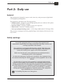
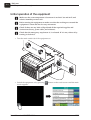
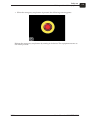
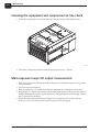
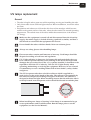
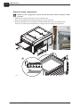
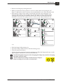
User’s Manual
CONCEPT 205 C
User's Manual
CONCEPT 205 C
T11376
Edition AF, July 2015
This book has part No 10073808 (GB)
0-4
#
Always read the Safety Instruction Manual part No 21741 before installing or
operating the equipment.
This manual is published by:
Glunz & Jensen Degraf S.p.A.
'Il Girasole' - Palazzo Donatello 8/03b
20084 Lacchiarella (MI)
Italy
Internet: www.degraf.glunz-jensen.com
Copyright © 2014 by Glunz & Jensen Degraf S.p.A.
User's Manual - CONCEPT 205 C
1517
0-5
Table of contents
Part 1: General information . . . . . . . . . . . . . . . . . . . . . . . . . . . . . . 1-1
About this manual . . . . . . . . . . . . . . . . . . . . . . . . . . . . . . . . . . . . . . . . . . . . . . . . 1-1
Intended use of this manual . . . . . . . . . . . . . . . . . . . . . . . . . . . . . . . . . . . . . . . 1-1
Reservations . . . . . . . . . . . . . . . . . . . . . . . . . . . . . . . . . . . . . . . . . . . . . . . . . . 1-1
Notes, cautions, and warnings ! . . . . . . . . . . . . . . . . . . . . . . . . . . . . . . . . . . . . . 1-1
Unintended use of the equipment. . . . . . . . . . . . . . . . . . . . . . . . . . . . . . . . . . . . 1-2
Intended use of the equipment. . . . . . . . . . . . . . . . . . . . . . . . . . . . . . . . . . . . . . 1-2
Installation . . . . . . . . . . . . . . . . . . . . . . . . . . . . . . . . . . . . . . . . . . . . . . . . . . . 1-2
Service assistance . . . . . . . . . . . . . . . . . . . . . . . . . . . . . . . . . . . . . . . . . . . . . . 1-2
Part 2: Daily use . . . . . . . . . . . . . . . . . . . . . . . . . . . . . . . . . . . . . . 2-1
General . . . . . . . . . . . . . . . . . . . . . . . . . . . . . . . . . . . . . . . . . . . . . . . . . . . . . . . . 2-1
Safety warnings . . . . . . . . . . . . . . . . . . . . . . . . . . . . . . . . . . . . . . . . . . . . . . . . . . 2-1
Initial operation of the equipment . . . . . . . . . . . . . . . . . . . . . . . . . . . . . . . . . . . . . . 2-2
Main screen description . . . . . . . . . . . . . . . . . . . . . . . . . . . . . . . . . . . . . . . . . . 2-4
Exposure section . . . . . . . . . . . . . . . . . . . . . . . . . . . . . . . . . . . . . . . . . . . . . 2-7
Processor section . . . . . . . . . . . . . . . . . . . . . . . . . . . . . . . . . . . . . . . . . . . . . 2-8
Light finisher section . . . . . . . . . . . . . . . . . . . . . . . . . . . . . . . . . . . . . . . . . 2-10
Dryer section . . . . . . . . . . . . . . . . . . . . . . . . . . . . . . . . . . . . . . . . . . . . . . . 2-11
Alarms . . . . . . . . . . . . . . . . . . . . . . . . . . . . . . . . . . . . . . . . . . . . . . . . . . . . . 2-12
List of alarms . . . . . . . . . . . . . . . . . . . . . . . . . . . . . . . . . . . . . . . . . . . . . . 2-15
Plate settings . . . . . . . . . . . . . . . . . . . . . . . . . . . . . . . . . . . . . . . . . . . . . . . . . 2-19
Plate selection . . . . . . . . . . . . . . . . . . . . . . . . . . . . . . . . . . . . . . . . . . . . . . . . 2-20
Part 3: Making plates. . . . . . . . . . . . . . . . . . . . . . . . . . . . . . . . . . . 3-1
Starting an exposure cycle . . . . . . . . . . . . . . . . . . . . . . . . . . . . . . . . . . . . . . . . . . . 3-1
Starting a washout cycle . . . . . . . . . . . . . . . . . . . . . . . . . . . . . . . . . . . . . . . . . . . . 3-1
Starting a dryer cycle . . . . . . . . . . . . . . . . . . . . . . . . . . . . . . . . . . . . . . . . . . . . . . 3-2
Starting a light finisher cycle . . . . . . . . . . . . . . . . . . . . . . . . . . . . . . . . . . . . . . . . . 3-2
Specific cycle. . . . . . . . . . . . . . . . . . . . . . . . . . . . . . . . . . . . . . . . . . . . . . . . . . 3-2
Part 4: Maintenance . . . . . . . . . . . . . . . . . . . . . . . . . . . . . . . . . . . 4-1
General . . . . . . . . . . . . . . . . . . . . . . . . . . . . . . . . . . . . . . . . . . . . . . . . . . . . . . . . 4-1
Filling up the cooler tank . . . . . . . . . . . . . . . . . . . . . . . . . . . . . . . . . . . . . . . . . . . . 4-1
Cleaning the equipment and compressed air line check. . . . . . . . . . . . . . . . . . . . . . . 4-2
Main exposure lamps UV output measurement. . . . . . . . . . . . . . . . . . . . . . . . . . . . . 4-2
UV lamps replacement . . . . . . . . . . . . . . . . . . . . . . . . . . . . . . . . . . . . . . . . . . . . . 4-3
General . . . . . . . . . . . . . . . . . . . . . . . . . . . . . . . . . . . . . . . . . . . . . . . . . . . . . . 4-3
Exposure lamps replacement . . . . . . . . . . . . . . . . . . . . . . . . . . . . . . . . . . . . . . . 4-4
Light finisher lamps replacement . . . . . . . . . . . . . . . . . . . . . . . . . . . . . . . . . . . . 4-6
1528
User's Manual - CONCEPT 205 C
0-6
User's Manual - CONCEPT 205 C
1517
General information
About this manual
Part 1: General information
About this manual
Intended use of this manual
This manual describes the common use procedures of the equipment. It is intended for
the daily user and should be kept with the equipment for reference at all times.
Reservations
• This manual was written and illustrated using the best possible information
available at the time of publication.
• Any differences between this manual and the equipment reflect improvements
introduced after the publication of the manual.
• Changes, technical inaccuracies and typographic errors will be corrected in
subsequent editions.
• As a part of our policy of continuous improvement, we reserve the right to alter
design and specifications without further notice.
Notes, cautions, and warnings !
Throughout the manual notes, cautions, and warnings are written in bold like the
example below:
"
Electrical installation must conform to local regulations and guidelines.
Symbol
Explanation
"
Note
The operator should observe and/or act according to the
information in order to obtain the best possible function of
the equipment.
$
Caution
The operator must observe and/or act according to the
information in order to avoid any mechanical or electrical
damage to the equipment.
#
1517
Meaning
Warning
The operator must observe and/or act according to the
information in order to avoid any personal injury.
User's Manual - CONCEPT 205 C
1-1
1-2
General information
About this manual
Unintended use of the equipment
Glunz & Jensen Degraf S.p.A. does not take any responsibility for any damage or
accidents caused by unintended use of the equipment:
• It is absolutely prohibited to make any modifications, electrical nor mechanical, of
the equipment. If however this prohibition is disregarded, Glunz & Jensen Degraf
S.p.A.'s warranty will no longer apply.
Intended use of the equipment
• This equipment is a part of a full range dedicated for the treatment of flexographic
printing plates. This range includes exposure, processor, dryer and light finisher.
• This equipment is designed to expose, process, dry and post-expose/light finish of
flexographic printing plates.
Installation
• Never install the equipment in explosive environments.
• It is the responsibility of the owner and operator/s of this equipment that the
installation is made in accordance with local regulations, and by engineers
authorized to carry out plumbing and electrical installations.
• Installation, service and repair must be performed only by Service Technicians who
are trained in servicing the equipment.
• The manufacturer cannot be held responsible for any damage caused by incorrect
installation of this equipment.
• The equipment is intended for installation in a restricted access location only.
Service assistance
• If help is needed to correct any problem with the equipment, please contact your
supplier.
User's Manual - CONCEPT 205 C
1517
Daily use
General
Part 2: Daily use
General
This equipment is designed to expose, wash, clean, dry, and post-expose/light finish
of flexographic printing plates.
The equipment is divided in the following sections:
• Washout section - designed to provide high quality and even washout of the plates
as well as high performance cleaning.
• Exposure section - 16 lamps of 60W to ensure even exposure.
• Dryer section - 4 drawers, 2 heating resistors.
• Post exposure/light finishing section - 11 UVA lamps (60W) and 10 UVC lamps (75W).
This processor is equipped with the graphical finger touch display which ensures very
easy control.
Safety warnings
To use this equipment safely, it is necessary that operators and
maintenance people follow the safety instructions and safety cautions and
warnings specified in the manuals.
The equipment is equipped with emergency switch which allows the
operators to stop the equipment in case of emergency. This emergency
switch cuts off the power supply of the entire equipment.
Make sure that the risk or the problem has been eliminated before
restoring the power on the equipment.
To release the emergency switch, turn it clockwise. The equipment has to
be restarted following the "Initial operation of the equipment" later in this
manual.
For the safety of operators, the equipment is equipped with interlock
switches for the opening of the exposure, dryer and light finisher drawers
during operation and for removing of the top panels of the equipment. If
any of the interlocks are not installed or closed, the equipment or a specific
section of the equipment will not operate. If an interlock is activated
during operation, the equipment or a specific section of the equipment
stops immediately the concerned section.
#
1517
For handling the plates use a safety gloves.
User's Manual - CONCEPT 205 C
2-1
2-2
Daily use
Initial operation of the equipment
Initial operation of the equipment
"
Make sure the room temperature is between 17 and 28°C (63 and 82°F) and
relative humidity on max. 80%.
"
Before turning the equipment on make sure that the working area around the
equipment is clean and free for easy movement.
"
Check if there are any leaks of liquid and all the required supplies and
connections (hoses, power cable, and exhausts).
"
Check that the emergency stop button (1) is released. If it is not, release it by
turning it clockwise.
• Turn the main switch (2) of the equipment on.
1
2
• Switch the equipment on by pressing
button on the touch screen until the main
screen appears.
User's Manual - CONCEPT 205 C
1528
Daily use
Initial operation of the equipment
• When the emergency stop button is pressed, the following screen appears.
Release the emergency stop button by turning it clockwise. The equipment returns to
the initial position.
1528
User's Manual - CONCEPT 205 C
2-3
2-4
Daily use
Initial operation of the equipment
Main screen description
The main screen looks like the one below.
Display overview
Description
By pressing this button the exposure section screen is accessed.
By pressing this button the processor section screen is accessed.
By pressing this button the light finisher section screen is accessed.
By pressing this button the dryer section 1/2 screen is accessed.
By pressing this button the dryer section 3/4 screen is accessed.
Allows to set/change plate parameters.
Allows to switch the equipment to manual functions mode, to access
hours counters, parameters setup and alarm history screens.
After pressing button, this button displays the status of request for
equipment switch off. According to the status of the equipment the
display shows the actual status of the power off request. If any
equipment cycle is active, "POWER OFF REQ" is displayed. As soon
as the equipment cycle is finished, button display switches to
"POWER OFF CLEAN", and as soon the cleaning cycle is finished,
button display switches to "POWER OFF TIMER". When the timer
ends, the equipment power goes off.
Allows to request equipment switch off.
This button is displayed, after pressing
button. By pressing this
button it is possible to cancel the request for the equipment switch off.
User's Manual - CONCEPT 205 C
1517
Daily use
Initial operation of the equipment
Status bars of individual sections on the left side of the main screen display the actual
status of the equipment sections.
Display overview
Description
Exposure section is ready to start an exposure.
EXPOSURE SECTION
Back exposure cycle is ongoing.
Back exposure cycle is stopped by the operator before
cycle end.
Main exposure cycle is ongoing.
Main exposure cycle is stopped by the operator before
cycle end.
Back or main exposure cycle is finished. To restart cycle it
is necessary to open and close exposure drawer.
Exposure drawer is opened during cycle.
Vacuum cycle is ongoing.
Processor section is ready to start processing of plate.
After cycle start, the solvent is checked. If the set
tolerance is exceeded, replace the solvent.
When solvent analysis is finished, the cycle starts.
PROCESSOR SECTION
Plate starts to move under wash out brushes in ahead direction according to the speed setting (tank solvent used).
Plate moves under wash out brushes in back direction
according to the speed setting (tank solvent used).
Plate moves under wash out brushes in ahead direction
according to the speed setting (tank solvent used).
When wash out cycle is finished, cleaning brush cycle
starts and stops according to the time setting.
Plate starts to move under wash out brushes in back
direction according to the speed setting (clean solvent
valve alternates to open and close according to set value).
Plate moves under wash out brushes in ahead direction
according to the speed set in the program (clean solvent
valve alternates to open and close according to set value).
When rinsing cycle finished, cleaning brush cycle starts
and stops according to the time setting.
Plate moves under wash out brushes in back direction
according to the speed setting (no solvent and wiping
brush down).
1517
User's Manual - CONCEPT 205 C
2-5
Daily use
Initial operation of the equipment
Display overview
Description
PROCESSOR SECTION
Cleaning brush cycle starts and stops according to the
time setting (fresh solvent used).
Brushes rotate without solvent according to the time
setting.
Processing of plate is finished. To restart cycle it is
necessary to open and close entrance cover.
Entrance cover is open. If the cover is opened during
cycle, the cycle stops.
Processing is stopped by operator before cycle end.
Light finisher section is ready to start a cycle.
LIGHT FINISHER SECTION
UVA lamp cycle is ongoing.
UVC lamp cycle is ongoing.
UVA lamp cycle followed by UVC lamp cycle is ongoing.
UVC lamp cycle followed by UVA lamp cycle is ongoing.
UVA lamp cycle is stopped by the operator before cycle
end.
Light finishing cycle is finished. To restart cycle it is
necessary to open and close light finisher drawer.
Light finisher drawer is opened during cycle.
Dryer 1 is ready to start a cycle.
Dryer 1 waits to start until temperature reaches setpoint.
Dryer 1 cycle is ongoing.
DRYER SECTION
2-6
Dryer 1 cycle is finished.
Dryer 1 drawer is open. If dryer/heater in cycle, then stops.
Heater 1 is not activated.
Heater 1 is activated and warming up to reach setpoint.
Dryer 1 temperature is reached
dryer 2, 3 and 4 status bars display the same kind of information as dryer 1 status bar
heater 2 status bar displays the same kind of information as heater 1 status bar
User's Manual - CONCEPT 205 C
1517
Daily use
Initial operation of the equipment
Exposure section
By pressing
button following exposure section screen is accessed.
By pressing
button is accessed plate list where it is possible to select
required plate stored in the memory.
"
It is possible to select program only if all cycles are off or finished.
Status bars on the left side of the screen inform about the time set for the cycle as well as
remaining time of the cycle for back and main exposure and actual value of vacuum cycle.
On the right side of the screen it is possible to start, stop or reset cycle.
After cycle start the
button changes to
. To stop the cycle press it. After
pressing it button changes back to
and yellow
button appears. Now it is
possible to reset or restart cycle by pressing on corresponding button.
To turn back to main screen press
By pressing
.
button following screen is displayed.
Here is displayed start and stop temperature set for cooling lamp and table as well as
their actual temperatures. As well here is displayed start and stop temperature set for
exposure exhauster, vacuum setpoint and actual value of UVA intensity. To turn back
to exposure section screen press
.
1517
User's Manual - CONCEPT 205 C
2-7
2-8
Daily use
Initial operation of the equipment
Processor section
By pressing
Keep
button following processor section screen appears.
button pressed until message "PLEASE WAIT" appears.
Wait untill "zero axis" is executed. Then the following screen appears automatically.
By pressing
button is accessed plate list where it is possible to select
required plate stored in the memory.
"
It is possible to select program only if all cycles are off or finished.
Status bars of the screen inform about various parameters set for all processing cycles.
As well it is possible to start, stop or reset cycle.
To start cycle press the
button and red
button appears. To stop the cycle
press it, and afterwards yellow
button appears. Now it is possible to reset or
restart cycle by pressing on corresponding button.
To turn back to main screen press
User's Manual - CONCEPT 205 C
.
1528
Daily use
Initial operation of the equipment
By pressing
button following screen is displayed.
From this screen it is possible to see the status of various pumps, valves, etc.
To turn back to processor section screen press
1517
.
User's Manual - CONCEPT 205 C
2-9
2-10
Daily use
Initial operation of the equipment
Light finisher section
By pressing
button following light finisher screen is displayed.
By pressing
button is accessed plate list where it is possible to select
required plate stored in the memory.
"
It is possible to select program only if all cycles are off or finished.
Status bars of the screen inform about the time setting and remaining time of the UVA
cycle, UVC cycle and combined sequence delay.
On the right side of the screen it is possible to start, stop or reset cycle.
After cycle start the
button changes to
. To stop the cycle press it. After
pressing it button changes back to
and yellow
button appears. Now it is
possible to reset or restart cycle by pressing on corresponding button.
To turn back to main screen press
User's Manual - CONCEPT 205 C
.
1528
Daily use
Initial operation of the equipment
Dryer section
By pressing
button following dryer screen is displayed.
By pressing
button is accessed plate list where it is possible to select
required plate stored in the memory.
"
It is possible to select program only if all cycles are off or finished.
Status bars of the screen inform about the time setting and remaining time of drying
cycle in dryer 1 and 2 as well about the set and actual temperature in dryer 1 and 2.
After cycle start the
button changes to
. To stop the cycle press it. After
pressing it button changes back to
and yellow
button appears. Now it is
possible to reset or restart cycle by pressing on corresponding button.
To turn back to main screen press
By pressing
.
button following screen is displayed.
Here is displayed the tolerance for start and stop temperature set for heater 1 as well as
its actual temperature. To turn back to dryer section screen press
.
The same kind of information is available for dryer 3/4 section. Press button
or
to switch between dryer sections.
1528
User's Manual - CONCEPT 205 C
2-11
2-12
Daily use
Initial operation of the equipment
Alarms
"
The accoustic signal occurs for 5 seconds when any automatic cycle is
finished.
When an alarm occurs, the
sign is displayed in the right top part of the main screen
and on the right side of the corresponding section status bar or in the corresponding
section screen.
The alarm indicates that the equipment is not in the condition to work in normal and
safe way. This prevents the use of the section affected by the alarm. When an alarm is
on, the acoustic signal is on too. Press on the alarm sign to display which alarm is
activated.
To turn back to main screen press
.
User's Manual - CONCEPT 205 C
1517
Daily use
Initial operation of the equipment
Symbol
Description
Water level is too low.
Exposure exhaust blower not working.
Error on the electronics.
External fresh solvent tank is empty.
At least one of the hours counters alarm is activated. Pressing this symbol
while its alarm is active displays the hours counters screen.
" required.
It is not possible to reset the counters. For this function password is
Compressed air pressure is too low.
One of top covers is open.
External used solvent tank is full.
Solvent level of internal solvent tank is too high.
Solvent level of internal solvent tank is too low.
No water circulation in exposure section.
No water circulation in washout section.
1517
User's Manual - CONCEPT 205 C
2-13
2-14
Daily use
Initial operation of the equipment
To go to alarm history screen press
displayed.
. Following screen is then
It is possible to see the time of alarm occurance and its description as well as to scroll
up and down the list and to the left and right to see whole alarm description.
According to the alarm number it is possible to identify the alarm. Please see the table
on the next pages.
To turn back to alarm screen press
.
It is possible to access alarm history from main screen too by pressing
and afterwards
button.
User's Manual - CONCEPT 205 C
button
1517
Daily use
Initial operation of the equipment
List of alarms
#
1517
For solving some alarms it is required to contact service technician. Do not
take any action which is not described in this manual.
Alarm
Message
Result
Cause/remedy
ALM01
Solvent overheating
Processor cycle start
inhibited
Safety solvent maximum temperature
reached (45°C), heating cycle stops until
solvent temperature reaches 42 C°.
ALM02
Flowmeter water table
not ok
Exposure cycle start
inhibited
If KP5 ON and S10 OFF after 1.5 sec
KP5 turns OFF and ALM02 appear.
With pump KP5 (water cooler exposure
table) ON, flowmeter sensor S10 (input
4.2) must be ON.
ALM03
Flowmeter water
solvent not ok
Processor cycle start
inhibited
If KP6 ON and S11 OFF after 1.5 sec
KP6 turns OFF and ALM03 appear.
With pump KP6 (water cooler exposure
table) ON, flowmeter sensor S11 (input
4.3) must be ON.
ALM04
Water cooling solvent
pump not ok
Processor cycle start
inhibited
Thermal relay QP6 (input 3.10) turns
OFF. Check for possible cause.
ALM05
Vacuum pump not ok
Exposure cycle start
inhibited
Thermal relay QP3 (input 3.07) turns
OFF. Check for possible cause.
ALM06
Dryer motor exhauster
not ok
Dryer cycle start
inhibited
Thermal relay QV4 (input 4.00) turns
OFF. Check for possible cause.
ALM07
Drye motor blower not
ok
Dryer cycle start
inhibited
Thermal relay QV5 (input 4.01) turns
OFF. Check for possible cause.
ALM08
LF exhauster motor
not ok
Signalization
Thermal relay QV3 (input 3.15) turns
OFF. Check for possible cause.
ALM09
Fresh solvent pump
not ok
Processor cycle start
inhibited
Thermal relay QP1 (input 3.05) turns
OFF. Check for possible cause.
ALM10
Washout pump not ok
Processor cycle start
inhibited
Thermal relay QP2 (input 3.06) turns
OFF. Check for possible cause.
ALM11
Analyser pump not ok
Processor cycle start
inhibited
Thermal relay QP4 (input 3.08) turns
OFF. Check for possible cause.
ALM12
Cooling expo pump
not ok
Exposure cycle start
inhibited
Thermal relay QP5 (input 3.09) turns
OFF. Check for possible cause.
ALM13
Motor brush not ok
Processor cycle start
inhibited
Thermal relay QM2 (input 3.11) turns
OFF. Check for possible cause.
ALM14
Motor brush
oscillation not ok
Processor cycle start
inhibited
Thermal relay QM3 (input 3.12) turns
OFF. Check for possible cause.
ALM15
Exhauster processor
not ok
Processor cycle start
inhibited
Thermal relay QV1 (input 3.13) turns
OFF. Check for possible cause.
ALM16
Water level cooling
solvent low
Processor cycle start
inhibited
Fill up water solvent tank. With water
solvent tank full input KL1 (2.00) must
be ON.
User's Manual - CONCEPT 205 C
2-15
2-16
Daily use
Initial operation of the equipment
Alarm
Message
Result
Cause/remedy
ALM17
Dirty solvent tank full
Processor cycle start
inhibited
Used solvent tank full. With used solvent
tank empty input IL5 ( 2.06) must be ON.
ALM18
Water level cooling
table low
Exposure cycle start
inhibited
Fill up water table tank. With water table
tank full input IL6 (2.07) must be ON.
ALM19
Washout tank
overlevel
Processor cycle start
inhibited
Washout tank reached maximum level.
With washout tank under the maximum
level input IL3 (2.03) must be ON.
ALM20
Air pressure mixing
Processor cycle start
inhibited
Check air pressure. With air pressure
ok input APS (2.08) must be ON.
ALM21
Heater solvent counter Processor cycle start
reached
inhibited
Hours/cycles counter setpoint reached.
Enter hours/cycles counter page and
reset the corresponding counter.
ALM22
Heater dryer 1-2
counter reached
Signalization
Hours/cycles counter setpoint reached.
Enter hours/cycles counter page and
reset the corresponding counter.
ALM23
Heater dryer 3-4
counter reached
Signalization
Hours/cycles counter setpoint reached.
Enter hours/cycles counter page and
reset the corresponding counter.
ALM24
UP down wip brush
counter reached
Signalization
Hours/cycles counter setpoint reached.
Enter hours/cycles counter page and
reset the corresponding counter.
ALM25
EL2 solvent valve
counter reached
Signalization
Hours/cycles counter setpoint reached.
Enter hours/cycles counter page and
reset the corresponding counter.
ALM26
EL3 solvent valve
counter reached
Signalization
Hours/cycles counter setpoint reached.
Enter hours/cycles counter page and
reset the corresponding counter.
ALM27
EL4 solvent valve
counter reached
Signalization
Hours/cycles counter setpoint reached.
Enter hours/cycles counter page and
reset the corresponding counter.
ALM28
EL5 solvent valve
counter reached
Signalization
Hours/cycles counter setpoint reached.
Enter hours/cycles counter page and
reset the corresponding counter.
ALM29
EL6 solvent valve
counter reached
Signalization
Hours/cycles counter setpoint reached.
Enter hours/cycles counter page and
reset the corresponding counter.
ALM30
KM2 wo brush
command counter
reached
Signalization
Hours/cycles counter setpoint reached.
Enter hours/cycles counter page and
reset the corresponding counter.
ALM31
KM3 wo brush
command counter
reached
Signalization
Hours/cycles counter setpoint reached.
Enter hours/cycles counter page and
reset the corresponding counter.
User's Manual - CONCEPT 205 C
1517
Daily use
Initial operation of the equipment
1517
Alarm
Message
Result
Cause/remedy
ALM32
KP1 wo brush
command counter
reached
Signalization
Hours/cycles counter setpoint reached.
Enter hours/cycles counter page and
reset the corresponding counter.
ALM33
Cover processor open
Signalization
With cover processor closed input KA3
(2.11) must be OFF.
ALM34
Dryer air pressure
not ok
Signalization
Check input PSW2 (2.13). It must be
ON.
ALM35
Not in use
ALM36
KP2 valve counter
reached
Signalization
Hours/cycles counter setpoint reached.
Enter hours/cycles counter page and
reset the corresponding counter.
ALM37
KP3 valve counter
reached
Signalization
Hours/cycles counter setpoint reached.
Enter hours/cycles counter page and
reset the corresponding counter.
ALM38
KP4 valve counter
reached
Signalization
Hours/cycles counter setpoint reached.
Enter hours/cycles counter page and
reset the corresponding counter.
ALM39
KP6 valve counter
reached
Signalization
Hours/cycles counter setpoint reached.
Enter hours/cycles counter page and
reset the corresponding counter.
ALM40
KP5 valve counter
reached
Signalization
Hours/cycles counter setpoint reached.
Enter hours/cycles counter page and
reset the corresponding counter.
ALM41
KRG1 valve counter
reached
Signalization
Hours/cycles counter setpoint reached.
Enter hours/cycles counter page and
reset the corresponding counter.
ALM42
KRG2 valve counter
reached
Signalization
Hours/cycles counter setpoint reached.
Enter hours/cycles counter page and
reset the corresponding counter.
ALM43
KV2 valve counter
reached
Signalization
Hours/cycles counter setpoint reached.
Enter hours/cycles counter page and
reset the corresponding counter.
ALM44
KV3 valve counter
reached
Signalization
Hours/cycles counter setpoint reached.
Enter hours/cycles counter page and
reset the corresponding counter.
ALM45
KVD valve counter
reached
Signalization
Hours/cycles counter setpoint reached.
Enter hours/cycles counter page and
reset the corresponding counter.
ALM46
KEXP valve counter
reached
Signalization
Hours/cycles counter setpoint reached.
Enter hours/cycles counter page and
reset the corresponding counter.
ALM47
KLFA valve counter
reached
Signalization
Hours/cycles counter setpoint reached.
Enter hours/cycles counter page and
reset the corresponding counter.
User's Manual - CONCEPT 205 C
2-17
2-18
Daily use
Initial operation of the equipment
Alarm
Message
Result
Cause/remedy
ALM48
KLFC valve counter
reached
Signalization
Hours/cycles counter setpoint reached.
Enter hours/cycles counter page and
reset the corresponding counter.
ALM49
Cover door open
during cycle
Signalization
Close cover door to restart cycle.
ALM50
Servo in alarm
emergency stop
request
Processor cycle start
inhibited
Servo motor goes in alarm. Press
emergency button then wait until the
message on the screen "SERVO ALARM
RESET IN PROGRESS" disappears.
ALM51
Fresh solvent empty
Processor cycle start
inhibited
Minimum level reached. With fresh
solvent tank full input L4_1( 2.04)
must be OFF.
ALM52
Expo exhauster motor
not ok
Exposure cycle start
inhibited
Thermal relay QV2 (input 3.14) turns
OFF. Check for possible cause.
ALM53
Minimum level
washout tank
Processor cycle start
inhibited
With washout tank not under the
minimum level input L2_1 (2.01) must
be OFF.
ALM54
Not in use
ALM55
L integrator
calibration not ok
Processor cycle start
inhibited
With light integrator function ON it is
not possible to run MAIN or BACK
expopsure cycle without CALIBRATION
DONE. Go to LIGHT INTEGRATOR and
perform AUTOLEARN CYCLE.
ALM56
Water cooling solvent
sensor not ok
Processor cycle
start, cooling and
solvent heating
inhibited
Analog input C1 does not work
correctly, check electrical wire
connection or replace the sensor.
ALM57
Solvent temp. sensor
not ok
Processor cycle start
and heating solvent
inhibited
Analog input C2 does not work
correctly, check electrical wire
connection or replace the sensor.
ALM58
Exposure lamp sensor
not ok
Processor cycle start
inhibited
Analog input C3 does not work
correctly, check electrical wire
connection or replace the sensor.
ALM59
Exposure table sensor
not ok
Cooling group of
exposure table
inhibited
Analog input C4 does not work
correctly, check electrical wire
connection or replace the sensor.
ALM60
Dryer 1-2 sensor not
ok
Heater dryer 1-2
inhibited
Analog input C5 does not work
correctly, check electrical wire
connection or replace the sensor.
ALM61
Dryer 3-4 sensor not
ok
Heater dryer 3-4
inhibited
Analog input C6 does not work
correctly, check electrical wire
connection or replace the sensor.
ALM62
Fresh solvent
minimum level
User's Manual - CONCEPT 205 C
Minimum level reached. With fresh
solvent tank full imput L4_2( 2.05)
must be ON.
1517
Daily use
Initial operation of the equipment
Plate settings
It is possible to store 24 plates with their process parameters.
Press
button from the main screen to access the exposure plate parameters
screen. In the bottom it is possible to go to plate parameters for processing, drying and
light finishing of the plate by pressing the corresponding button.
Exposure parameters
Light finisher parameters
Dryer parameters
Processor parameters
By pressing
button (in the left top corner) is accessed plate list where it is
possible to select required plate stored in the memory.
On each screen it is possible to modify the name of the plate as well as the dedicated
parameters. When done press
to store modified parameters/name.
1517
User's Manual - CONCEPT 205 C
2-19
2-20
Daily use
Initial operation of the equipment
When the correct plate is displayed, press required button to change the plate name or
one of the parameters to change it. An alphanumeric keyboard for the plate name or
numeric keyboard for other parameters is then displayed.
Alphanumeric keyboard
Numeric keyboard
"
In all cases, after typing in a new value, always confirm the input by pressing
"ENT" button. Not doing this may result in corrupted values memorisation.
"
The name plate from the same channel is common for all sections. Modifying
the plate name from one channel in one section will modify the plate name in
other section.
Plate selection
• From the main screen enter the section which requested to process. Press
to choose required plate. When done, press
concerned section.
User's Manual - CONCEPT 205 C
to start to operate the
1517
Making plates
Starting an exposure cycle
Part 3: Making plates
Starting an exposure cycle
#
For handling the plates use a safety gloves.
• Pull out the exposure drawer and put the plate on the cooled table to make the back
or main exposure.
• Enter the exposure section from the main screen. Select the required plate type from
the plate list.
• Make sure the back and main exposure parameters are correct.
"
Successful back exposure requires the UVA lamps are at peak output in the
beginning of the back exposure cycle. This requires a pre-heat step prior to doing
the back exposure of the plate. This is secured by running a short main exposure
cycle with no plate on the table. Run a 5 minute main exposure cycle, allowing
the lamps to reach the operating temperature, at which time the fans activate. The
main exposure can be cancelled once the lamps are fully pre-heated.
• When running back exposure cycle, vacuum cycle is not in use.
• When running main exposure cycle on conventional plate, put the vacuum foil on
top of the plate and film (not required for back exposure or for digital plates).
button from vacuum section of exposure section
• Start the vacuum by pressing
screen. When exposure finished, stop vacuum by pressing
.
• Close the exposure drawer.
• To start an exposure, press
button of back or main exposure section.
Starting a washout cycle
#
For handling the plates use a safety gloves.
• Open the entrance cover and fix the plate on the transport table.
"
Make sure the sticky sheet is dry enough to secure proper fixing of the plate.
• Enter the processor section from the main screen. Select the required plate type
from the plate list.
• Make sure the processing parameters are correct.
• Close the entrance cover.
• To start cycle, press
1517
button of the processor section screen.
"
Be aware that after pressing
button, the solvent analyzer performs the
check of solvent contamination for approx. 15 seconds. If needed, pumps perform
refresh of solvent according to setup, otherwise process starts immediately.
"
#
It is recommended to secure that the sticky sheet is dry enough after each
processed plate. It secures proper fixation of the plate.
In case the sticky sheet is not fully covered with the plate(s) to process, the
area which is not covered by plate(s) should be covered with e.g. a piece of
flexo plate to prevent long contact between the sticky sheet and the solvent.
This helps to prolong lifetime of the sticky sheet significantly.
User's Manual - CONCEPT 205 C
3-1
3-2
Making plates
Starting a dryer cycle
Starting a dryer cycle
#
For handling the plates use a safety gloves.
• Pull out the dryer drawer and put the plate in.
• Enter the dryer section from the main screen. Select the required plate type from the
plate list.
• Make sure the drying parameters are correct.
• Close the dryer drawer.
button of the corresponding dryer section.
• To start cycle, press
Starting a light finisher cycle
#
For handling the plates use a safety gloves.
• Pull out the light finisher drawer and put the plate in.
• Enter the light finisher section from the main screen. Select the required plate type
from the plate list.
• Make sure the light finishing parameters are correct.
• Close the light finisher drawer.
• To start cycle, press
button of the corresponding light finishing (UVA cycle,
UVC cycle or combined sequence) section.
Specific cycle
The equipment offers the possibility to have an automatic sequence of light finishing.
If this function has been enabled (refer to "Equipment setup" in the equipment's
Service Manual) the cycle proceeds as followed:
• if UVA --> UVC is selected, then UVA cycle is followed by UVC cycle after a preset
delay,
• if UVC --> UVA is selected, then UVC cycle is followed by UVA cycle after a preset
delay.
User's Manual - CONCEPT 205 C
1517
Maintenance
General
Part 4: Maintenance
General
Maintenance activities are listed in the Maintenance Chart delivered with the
equipment.
Filling up the cooler tank
#
This operation has to be carried out with the equipment switched off.
• Unlock the side panel by using triangle shaped key and remove it.
• Remove the cover of the cooler tank.
T33115
• Prepare necessary amount of a solution based on 70% of demineralized/distilled
water, 30% of ethylene glycol and a few drops of algaecide (antifoam action).
• Fill the tank to the maximum.
1517
User's Manual - CONCEPT 205 C
4-1
4-2
Maintenance
Cleaning the equipment and compressed air line check
Cleaning the equipment and compressed air line check
• Clean the equipment covers from dust and dirt by using a clean damp cloth.
T33116
• Check the compressed air lines and its supply pressure (6 - 10 bar).
Main exposure lamps UV output measurement
• Pull out the exposure drawer and place the sensor of a Kühnast meter on top of the
•
•
•
•
exposure table.
Close the exposure drawer.
Run an exposure cycle. Make sure that the temperature of lamps is at least 38°C.
Repeat the UV output measurement at another eight points of the exposure table by
using a Kühnast meter. Record the data in a UVA spreadsheet with average output,
and % maximum variation.
When finished and replacement of lamps is not needed, pull out the exposure
drawer, remove the sensor and close the exposure drawer again.
User's Manual - CONCEPT 205 C
1517
Maintenance
UV lamps replacement
UV lamps replacement
General
• The tube is fragile, take a great care while unpacking, moving and installing the tube.
• Only clean tubes ensure uniform light emission. Before installation, ensure the tubes
are clean.
• Perspiration and sebaceous oil from the skin form white smudges which become
etched on the quartz surface of the tube, when the tube reaches its normal operating
temperature. The etched areas of the tubes inhibit the transmission of the desired
UV energy.
#
Make sure the equipment is turned off and disconnected from the electricity
supply, the mains supply is locked off using a padlock or similar, and then a
check made to ensure that the equipment will not run.
#
Do not handle the tubes with bare hands. Wear cut resistant gloves.
#
Always use safety glasses when handling lamps.
#
Fluorescent tubes contain small amounts of mercury. Used lamps should be
disposed according to local laws and regulation.
#
UV-C light radiation is dangerous for human skin and particularly the eyes.
Even a short exposure time may cause burnings in the lower skin layers and
damages the eyes retina. Due to the safety systems installed, it should never be
required to check the UV-C tubes by view the UV-C light directly when
operating, maintaining or servicing the equipment. However, in case of need
it is mandatory to wear a welding helmet with at least shade 6, safety clothes
and gloves.
"
The UVA exposure tubes have a built-in reflector which is applied in a
semi-circle over the entire length of the tube. The reflector is recognizable by
the white no transparent colouring of the glass in the tube. The reflector is
designed to direct the light. When installing ensures that the reflection side is
correctly located (non transparent section should be directed toward the plate.
160°
"
1517
When installing new lamps a "burning" of the lamps is recommended to get
correct performance and to stabilize them. Run the lamps prior to use the
equipment (see the Service Manual).
User's Manual - CONCEPT 205 C
4-3
4-4
Maintenance
UV lamps replacement
Exposure lamps replacement
#
Make sure the equipment is turned off and the main switch is locked in "OFF"
position.
• Pull out the exposure drawer on the maximum (a).
• Remove the right bottom side panel closest to the front (b).
• Remove locking screw securing the lamps holder drawer (c) and pull out the
drawer. Use the exposure drawer as a support (d) according to the picture.
c
a
ax.
on
m
the
b
d
T33421
User's Manual - CONCEPT 205 C
1517
Maintenance
UV lamps replacement
• Remove the lamps by turning them 90°.
• Make sure that the socket position is correct on both sides for inserting the UV
lamp. To adjust the socket correctly it is recommended to use a flat screwdriver (2).
• Insert the new lamp in the socket on both sides and lock it by turning 90° (4).
Note the little mark on the UV lamp ring which must be in line with the socket
opening when the lamp is installed correctly (5). Make sure that the lamps are
installed in alternate left/right position to ensure proper light distribution (6).
1
3
2
incorrect
correct
5
4
6
incorrect
90°
PHILLIPS
TL80W/10R
DANGER:
correct
Ultraviolet Radiaton
Avoid Exposure
Follow Warning Notice
PHILLIPS
TL80W/10R
DANGER:
Ultraviolet Radiaton
Avoid Exposure
Follow Warning Notice
T33420
• Push the lamps holder drawer in.
• Secure the lamps holder drawer with the locking screw.
• Close the exposure drawer.
• Unlock the main switch and turn the equipment on. Burn the lamps and carry out the
light integrator calibration (see the Service Manual).
"
#
1517
Recalibrating light integrator after changing the lamps may result in changing
the plate exposure times.
The UVA fluorescent lamps contain mercury. Dispose
them according to local, state or federal laws.
Hg
User's Manual - CONCEPT 205 C
4-5
Maintenance
UV lamps replacement
Light finisher lamps replacement
#
Make sure the equipment is turned off and the main switch is locked in "OFF"
position.
• Pull out the light finisher drawer on the maximum (a).
• Remove the right bottom side panel closest to the front (b).
• Remove locking screw securing the lamps holder drawer (c) and pull out the
drawer. Use the light finisher drawer as a support (d) according to the picture.
$
Always put the lamps holder drawer on the support between two thicker
lamps!
c
m
ax
.
a
th
e
b
on
4-6
d
T33422
User's Manual - CONCEPT 205 C
1517
Maintenance
UV lamps replacement
• Remove the lamps by turning them 90°.
• Make sure that the socket position is correct on both sides for inserting the UV
lamp. To adjust the socket correctly it is recommended to use a flat screwdriver (2).
• Insert the new lamp in the socket on both sides and lock it by turning 90° (4).
Note the little mark on the UV lamp ring which must be in line with the socket
opening when the lamp is installed correctly (5). Make sure that the lamps are
installed in alternate left/right position to ensure proper light distribution (6).
1
3
2
incorrect
correct
5
4
6
incorrect
90°
PHILLIPS
TL80W/10R
DANGER:
correct
Ultraviolet Radiaton
Avoid Exposure
Follow Warning Notice
PHILLIPS
TL80W/10R
DANGER:
Ultraviolet Radiaton
Avoid Exposure
Follow Warning Notice
T33420
• Push the lamps holder drawer in.
• Secure the lamps holder drawer with the locking screw.
• Close the light finisher drawer.
• Unlock the main switch and turn the equipment on. Burn the lamps.
#
1517
The UVA and UVC fluorescent lamps contain mercury.
Dispose them according to local, state or federal laws.
Hg
User's Manual - CONCEPT 205 C
4-7
4-8
Maintenance
UV lamps replacement
User's Manual - CONCEPT 205 C
1517