1
NEC Express5800/BladeServer Series
N8400-055AF/078F/079F
NEC Express5800/B140a-T
User's Guide
1st Edition
9-2008
ONL-540_001_03-B140aT-100-99-0809
PROPRIETARY NOTICE AND LIABILITY DISCLAIMER
The information disclosed in this document, including all designs and related materials, is the
valuable property of NEC Corporation (NEC) and /or its licensors. NEC and/or its licensors, as
appropriate, reserve all patent, copyright and other proprietary rights to this document, including all
design, manufacturing, reproduction, use, and sales rights thereto, except to the extent said rights are
expressly granted to others.
The NEC product(s) discussed in this document are warranted in accordance with the terms of the
Warranty Statement accompanying each product. However, actual performance of each such
product is dependent upon factors such as system configuration, customer data, and operator control.
Since implementation by customers of each product may vary, the suitability of specific product
configurations and applications must be determined by the customer and is not warranted by NEC.
To allow for design and specification improvements, the information in this document is subject to
change at any time, without notice. Reproduction of this document or portions thereof without prior
written approval of NEC is prohibited.
First Printing, September 2008
Copyright 2008
NEC Corporation
7-1 Shiba 5-Chome, Minato-Ku
Tokyo 108-8001, Japan
All Rights Reserved
Printed in Japan
Keep this User's Guide at hand for quick reference at anytime necessary.
SAFETY INDICATIONS
Follow the instructions in this User's Guide for your safety to use the server.
The server contains components with possible danger, hazards that may cause by ignoring warnings,
and preventive actions against such hazards.
Server components with possible danger are indicated with a warning label placed on or around them
as well as described in this User's Guide.
In the User's Guide or warning labels, "WARNING" or "CAUTION" is used to indicate a degree of
danger. These terms are defined as follows:
WARNING
CAUTION
Indicates the presence of a hazard that may result in death or serious
personal injury if the instruction is ignored.
Indicates the presence of a hazard that may cause minor personal injury,
including burns, or property damage if the instruction is ignored.
Precautions and notices against hazards are presented with one of the following three symbols. The
individual symbols are defined as follows:
This symbol indicates the presence of a hazard if the instruction is ignored.
An image in the symbol illustrates the hazard type. (Attention)
This symbol indicates prohibited actions. An image in the symbol illustrates a particular
prohibited action. (Prohibited Action)
This symbol indicates mandatory actions. An image in the symbol illustrates a
mandatory action to avoid a particular hazard. (Mandatory Action)
(Example)
(Example)
Symbol to draw attention
Description of a danger
Term indicating a degree of danger
CAUTION
Plug in to a proper power source.
Use a proper wall outlet. Use of an improper power source may cause a fire or a
power leak.
Symbols used in this User's Guide and warning labels are listed below.
Attentions
Indicates that improper use may cause an electric shock.
Indicates that improper use may cause fumes or fire.
Indicates that improper use may cause fingers to be caught.
Indicates that improper use may cause personal injury by the moving fan blades.
Indicates that improper use may cause personal injury.
Indicates that improper use may cause explosion.
Indicates a general notice or warning that cannot be specifically identified.
Prohibited Actions
Do not disassemble, repair, or modify the server. Otherwise, an electric shock or fire
may be caused.
Do not touch any component other than specified. Otherwise, an electric shock or
personal injury such as burns may be caused.
Keep away from fire. Otherwise, an ignition may be caused.
Keep away from water or liquid. Otherwise, an electric shock or fire may be caused.
Indicates a general prohibited action that cannot be specifically identified.
Mandatory Action
Unplug the power cord of the server. Otherwise, an electric shock or fire may be
caused.
Indicates a mandatory action that cannot be specifically identified. Make sure to follow
the instruction.
NOTE: This equipment has been tested and found to comply with the limits for a Class A digital
device, pursuant to Part 15 of the FCC Rules. These limits are designed to provide reasonable
protection against harmful interference when the equipment is operated in a commercial
environment. This equipment generates, uses, and can radiate radio frequency energy and, if not
installed and used in accordance with the instruction manual, may cause harmful interference to
radio communications. Operation of this equipment in a residential area is likely to cause harmful
interference in which case the user will be required to correct the interference at his own expense.
Trademarks
NEC ESMPRO and NEC EXPRESSBUILDER are trademarks of NEC Corporation.
Microsoft, Windows, Windows Server, Windows NT, and MS-DOS are registered trademarks or trademarks of Microsoft
Corporation in the United States and other countries.
Intel, Intel logo, Xeon, and Xeon Inside are registered trademarks of Intel Corporation in the United States and other
countries.
Datalight is a registered trademark of Datalight, Inc.
ROM-DOS is a trademark of Datalight, Inc.
AT is a registered trademark of International Business Machines Corporation in the United States and other countries.
LSI and the LSI logo design are trademarks or registered trademarks of LSI Corporation.
Adaptec and its logo is a registered trademark of Adaptec, Inc. of United States.
SCSISelect is a trademark of Adaptec, Inc. of the United States.
Adobe, Adobe logo, and Acrobat are trademarks of Adobe Systems Incorporated.
All other product, brand, or trade names used in this publication are the trademarks or registered trademarks of their
respective trademark owners.
Windows Server 2008 stands for Microsoft® Windows Server® 2008 Standard Operating system and Microsoft® Windows
Server® 2008 Enterprise operating system. Windows Vista stands for Microsoft® Windows Vista® Business operating
system. Windows Server 2003 x64 Editions stands for Microsoft® Windows Server® 2003 R2, Standard x64 Edition
Operating system and Microsoft® Windows Server® 2003 R2, Enterprise x64 Edition operating system, or Microsoft®
Windows Server® 2003, Standard x64 Edition operating system and Microsoft® Windows Server® 2003, Enterprise x64
Edition operating system. Windows Server 2003 stands for Microsoft® Windows Server® 2003 R2, Standard Edition
operating system and Microsoft® Windows Server® 2003 R2, Enterprise Edition operating system, or Microsoft® Windows
Server® 2003, Standard Edition operating system and Microsoft® Windows Server® 2003, Enterprise Edition operating
system. Windows XP x64 Edition stands for Microsoft® Windows® XP Professional x64 Edition operating system.
Windows XP stands for Microsoft® Windows® XP Home Edition operating system and Microsoft® Windows® XP
Professional operating system. Windows 2000 stands for Microsoft® Windows® 2000 Server operating system and
Microsoft® Windows® 2000 Advanced Server operating system, and Microsoft® Windows® 2000 Professional operating
system. Windows NT stands for Microsoft® Windows NT® Server network operating system version 3.51/4.0 and
Microsoft® Windows NT® Workstation operating system version 3.51/4.0. Windows Me stands for Microsoft® Windows®
Millennium Edition operating system. Windows 98 stands for Microsoft® Windows®98 operating system. Windows 95
stands for Microsoft® Windows®95 operating system.
Momentary voltage drop prevention:
This product may be affected by a momentary voltage drop caused by lightning. To prevent a
momentary voltage drop, an AC uninterruptible power supply (UPS) unit should be used.
Notes:
(1) No part of this manual may be reproduced in any form without the prior written permission of
NEC Corporation.
(2) The contents of this User's Guide may be revised without prior notice.
(3) The contents of this User's Guide shall not be copied or altered without the prior written
permission of NEC Corporation.
(4) All efforts have been made to ensure the accuracy of all information in this User's Guide. If
you notice any part unclear, incorrect, or omitted in this User's Guide, contact the service
representative where you purchased this product.
(5) NEC assumes no liability arising from the use of this product, nor any liability for incidental or
consequential damages arising from the use of this User's Guide regardless of Item (4).
i
PREFACE
Welcome to the NEC Express5800/BladeServer series server.
The NEC Express5800/BladeServer holds powerful performance and employs the latest technology
to implement a computer for the next generation. With its potential capabilities, the server may be
used as the workstation PC that configures a client-server system and provides high-speed
processing and superior reliability.
Read this User's Guide thoroughly to fully understand handling of the server and appreciate its
functions to the maximum extent.
ii
ABOUT THIS USER'S GUIDE
This User's Guide is a guide for proper setup and use of the server.
This User's Guide also covers useful procedures for dealing with difficulties and problems that may
arise during setup or operation of the server.
Keep this manual for future use.
The following describes how to proceed with this User's Guide.
How to Use This User's Guide
To aid you in finding information quickly, this User's Guide contains the following information:
Chapter 1 Notes on Using Your Server
includes information that needs attention to use the CPU blade. Make sure to read this
chapter before setting up and using the CPU blade. It also includes requirements and
advisory information for transfer and disposal of the CPU blade.
Chapter 2 General Description
includes information necessary to use the CPU blade, such as names and functions of its
components.
Chapter 3 Setting Up Your Server
tells you how to select a site, unpack the system, make cable connections, and power on
your system.
Chapter 4 Configuring Your Server
tells you how to configure the system and provides instructions for running the BIOS Setup
Utility and the RAID Configuration Utility, which is used to configure RAID drive in your
system.
Chapter 5 Installing the Operating System
describes how to install the operating system.
Chapter 6 Installing and Using Utilities
describes how to install the utilities for the server. It also includes a description on using the
attached "NEC EXPRESSBUILDER" DVD.
Chapter 7 Maintenance
provides you with all the information necessary to maintain successful operation of the CPU
blade.
Chapter 8 Troubleshooting
contains helpful information for solving problems that might occur with your system.
Chapter 9 Upgrading Your Server
provides you with instructions for upgrading your system with an additional processor,
optional memory, optional mezzanine cards, and hard disk drives.
Appendix A Specification
provides specifications for your CPU blade.
Appendix B Installing the Operating System
describes how to install Microsoft Windows Server 2003 x64 Editions and Windows Server
2003 without using Express Setup.
iii
Text Conventions
The following conventions are used throughout this User's Guide. For safety symbols, see
"SAFETY INDICATIONS" provided earlier.
IMPORTANT:
Items that are mandatory or require attention when using the server
NOTE:
Helpful and convenient piece of information
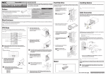
IN THE PACKAGE
The carton contains various accessories, as well as the server itself. See the packing list to make
sure that you have everything and that individual components are not damaged. If you find any
component missing or damaged, contact your service representative.
Store the provided accessories in a designated place for your convenience. You will need
them to install an optional device or troubleshoot the server, as well as to set it up.
Make a backup copy of each provided floppy disk, if any. Store the original disk as the
master disk in a designated place, and use its copy.
Improper use of any provided floppy disk or DVD/CD-ROM may alter your system
environment. If you find anything unclear, immediately ask your service representative for
help.
iv
CONTENTS
Preface ..............................................................................................................................................i
About This User's Guide..................................................................................................................ii
In the Package................................................................................................................................ iii
Chapter 1 Notes on Using Your Server ........................................................................ 1-1
Safety Notes................................................................................................................................. 1-2
For Proper Operation ................................................................................................................... 1-5
Transfer to Third Party................................................................................................................. 1-7
Disposal and Consumables .......................................................................................................... 1-8
User Support ................................................................................................................................ 1-9
Chapter 2 General Description ..................................................................................... 2-1
Overview...................................................................................................................................... 2-2
Standard Features......................................................................................................................... 2-3
Part Names and Controls ............................................................................................................. 2-4
Front View ............................................................................................................................... 2-4
Rear View ................................................................................................................................ 2-6
Internal View ........................................................................................................................... 2-7
External View .......................................................................................................................... 2-9
Hard Disk Drive .................................................................................................................... 2-10
Lamp Indications ....................................................................................................................2-11
Using Your Server...................................................................................................................... 2-14
Power-on of Blade Server...................................................................................................... 2-14
POST ..................................................................................................................................... 2-16
Power-off of Blade Server ..................................................................................................... 2-19
Device Identification ............................................................................................................. 2-20
Chapter 3 Setting Up Your Server ................................................................................ 3-1
Before Installing CPU Blade ....................................................................................................... 3-2
Check of MAC Address........................................................................................................... 3-2
Installing DIMM...................................................................................................................... 3-3
Installing the CPU Blade ............................................................................................................. 3-4
Installing the Hard Disk Drive ..................................................................................................... 3-4
Making Connections .................................................................................................................... 3-5
Network ................................................................................................................................... 3-8
v
Chapter 4 Configuring Your Server.............................................................................. 4-1
System BIOS ~ SETUP ~ .............................................................................................................4-1
Starting SETUP Utility.............................................................................................................4-2
Description on On-Screen Items and Key Usage .....................................................................4-3
Configuration Examples...........................................................................................................4-4
Menu and Parameter Descriptions ...........................................................................................4-8
RAID System Configuration ......................................................................................................4-29
RAID......................................................................................................................................4-29
Features of On-board RAID Controller (MegaRAID ROMB)...............................................4-34
Before Using WebBIOS .........................................................................................................4-39
Using WebBIOS .....................................................................................................................4-41
Configuring Virtual Disk........................................................................................................4-54
Operation of Various Features ................................................................................................4-71
WebBIOS and Universal RAID Utility ..................................................................................4-81
Battery for On-board RAID Controller (MegaRAID ROMB) ...............................................4-84
Chapter 5 Installing the Operating System with Express Setup............................... 5-1
About Express Setup ....................................................................................................................5-2
Microsoft Windows Server 2003 ..................................................................................................5-3
Notes on Windows Installation.................................................................................................5-3
Flow of Setup ...............................................................................................................................5-8
Installing the Windows Server 2003.............................................................................................5-9
Installing and Setting Device Drivers.........................................................................................5-18
PROSet...................................................................................................................................5-18
Optional Network Board Driver.............................................................................................5-20
Adapter Fault Tolerance (AFT)/Adaptive Load Balancing (ALB).........................................5-21
Setting WOL ..........................................................................................................................5-23
Graphics Accelerator Driver...................................................................................................5-24
Installing N8403-018 FibreChannel Controller......................................................................5-24
Available switch options for Windows Server 2003 Boot.ini file ..........................................5-25
Setting for Solving Problems......................................................................................................5-26
Memory Dump (Debug Information).....................................................................................5-26
Windows Dr. Watson..............................................................................................................5-29
Network Monitor....................................................................................................................5-30
Installing Maintenance Utilities..................................................................................................5-31
Updating the System...................................................................................................................5-31
Making Backup Copies of System Information..........................................................................5-32
Installing with the OEM-FD for Mass Storage Device ..........................................................5-33
vi
Chapter 6 Installing and Using Utilities ....................................................................... 6-1
NEC EXPRESSBUILDER .......................................................................................................... 6-2
Autorun Menu ......................................................................................................................... 6-6
Parameter File Creator ................................................................................................................. 6-7
Parameter File.......................................................................................................................... 6-8
NEC ESMPRO .......................................................................................................................... 6-18
Universal RAID Utility.............................................................................................................. 6-19
Setup with Express Setup ...................................................................................................... 6-19
Manual Setup......................................................................................................................... 6-19
Using Universal RAID Utility via Network .......................................................................... 6-19
NEC DianaScope ....................................................................................................................... 6-20
Chapter 7 Maintenance.................................................................................................. 7-1
Making Backup Copies................................................................................................................ 7-1
System Diagnostics...................................................................................................................... 7-2
Test Items ................................................................................................................................ 7-2
Startup and Exit of System Diagnostics .................................................................................. 7-3
Chapter 8 Troubleshooting ........................................................................................... 8-1
System Viewers............................................................................................................................ 8-2
Error Messages ............................................................................................................................ 8-3
POST Error Messages ............................................................................................................. 8-3
Error Messages on Virtual LCD ............................................................................................ 8-20
Lamps ........................................................................................................................................ 8-41
Solving Problems ....................................................................................................................... 8-42
CPU Blade............................................................................................................................. 8-42
Problems with Windows........................................................................................................ 8-49
Problems with NEC EXPRESSBUILDER............................................................................ 8-54
Problems with Express Setup ................................................................................................ 8-55
Problems with Parameter File Creator................................................................................... 8-55
Problems with RAID System and RAID Controller.............................................................. 8-56
Collecting Event Log ................................................................................................................. 8-58
Collecting Configuration Information........................................................................................ 8-59
Collecting Dr. Watson Diagnostic Information.......................................................................... 8-60
Memory Dump........................................................................................................................... 8-60
Recovery for Windows System.................................................................................................. 8-61
Maintenance Tools ..................................................................................................................... 8-62
Starting Maintenance Tools ................................................................................................... 8-62
Function of Maintenance Tools ............................................................................................. 8-64
Maintenance Tools with Remote Console ............................................................................. 8-66
Resetting the CPU blade ............................................................................................................ 8-68
Forced Shutdown ....................................................................................................................... 8-68
vii
Chapter 9 Upgrading Your Server ................................................................................ 9-1
Safety Notes..................................................................................................................................9-2
Anti-static Measures .....................................................................................................................9-3
Preparation for Installation ...........................................................................................................9-4
Installation/Removal Procedure....................................................................................................9-5
Processor (CPU).......................................................................................................................9-5
DIMM ....................................................................................................................................9-14
Mezzanine Card .....................................................................................................................9-24
Hard Disk Drive .....................................................................................................................9-29
Appendix A
Specifications............................................................................................A-1
Appendix B
Installing the Operating System..............................................................B-1
Setup and Re-setup of CPU Blade of Diskless Model................................................................. B-1
Local Installation..................................................................................................................... B-1
Remote Desktop for Management ............................................................................................. B-28
Windows Server 2008 ........................................................................................................... B-28
Windows Server 2003 x64 Editions ...................................................................................... B-28
Windows Server 2003 ........................................................................................................... B-29
Setup of Device Driver (Normally Installed in Server) ............................................................. B-30
PROSet.................................................................................................................................. B-30
Graphics Accelerator ............................................................................................................. B-32
Fibre Channel Controller Driver ........................................................................................... B-32
Optional Network Board Driver............................................................................................ B-33
Setup of Adapter Fault Tolerance (AFT)/Adaptive Load Balancing (ALB).............................. B-35
Setup Teaming....................................................................................................................... B-36
Remove Team........................................................................................................................ B-38
Setting WOL.............................................................................................................................. B-39
Re-installation of the Network Driver ....................................................................................... B-41
Setting for Solving Problems..................................................................................................... B-43
Memory Dump (Debug Information) - Windows Server 2008 - ........................................... B-43
Memory Dump (Debug Information) - Windows Server 2003 - ........................................... B-46
How to Create a User-mode Process Dump File ................................................................... B-49
Network Monitor................................................................................................................... B-51
Re-installing the Operation System if Multiple Logical Drives Exist................................... B-53
Updating the System - Applying Service Pack -........................................................................ B-55
Local Update ......................................................................................................................... B-56
Update from TS Client (Windows Server 2008) ................................................................... B-64
Update from TS Client (Windows Server 2003 x64 Editions) .............................................. B-65
Update from TS Client (Windows Server 2003) ................................................................... B-68
About Windows Activation ................................................................................................... B-71
viii
(This page is intentionally left blank.)
Chapter 1
Notes on Using Your Server
This chapter includes information necessary for proper and safe operation of the server.
1-2 Notes on Using Your Server
SAFETY NOTES
This section provides notes on using the server safely. Read this section carefully to ensure proper
and safe use of the server. For symbols, see "SAFETY INDICATIONS" provided earlier.
For part names described in the safety instruction chapter in this guide, refer to "Features and
Controls" in Chapter 2.
WARNING
Do not use the server for services where critical high availability may directly
affect human lives.
The server is not intended to be used with or control facilities or devices
concerning human lives, including medical devices, nuclear facilities and
devices, aeronautics and space devices, transportation facilities and devices;
and facilities and devices requiring high reliability. NEC assumes no liability
for any accident resulting in personal injury, death, or property damage if the
server has been used in the above conditions.
Do not disassemble, repair, or alter the server.
Never attempt to disassemble, repair, or alter the server on any occasion
other than described in this User's Guide. Failure to follow this instruction may
cause an electric shock or fire as well as malfunctions of the server.
Do not remove the battery.
Your server contains the lithium and NiMH (or Li-Ion) batteries. Do not
remove the battery. Danger of explosion if the battery is incorrectly replaced.
Placing the battery close to a fire or in the water may cause an explosion.
When the server does not operate appropriately due to the dead batteries,
contact your service representative to replace the battery. Do not
disassemble the server to replace or recharge the battery by yourself.
Do not use the server if any smoke, odor, or noise is present.
If smoke, odor, or noise is present, immediately turn off the system and
disconnect the power plug from the outlet, then contact your service
representative. Using the server in such conditions may cause a fire.
Keep needles or metal objects away from the server.
Do not insert needles or metal objects into ventilation holes in the server.
Doing so may cause an electric shock.
Use the devices only in the specified areas.
CPU blades and hard disk drives should be installed in the dedicated Blade
Enclosure for their uses. Do not install the CPU blades and hard disk drives in
a chassis other than the Blade Enclosure. Failure to follow it may result in fire
and/or electric shock to occur.
Notes on Using Your Server 1-3
WARNING
Do not use the equipment in the place where corrosive gases exist.
Make sure not to locate or use the server in the place where corrosive gases
(sulfur dioxide, hydrogen sulfide, nitrogen dioxide, chlorine, ammonia, ozone,
etc) exist.
Also, do not set it in the environment where the air (or dust) includes
components accelerating corrosion (ex. sulfur, sodium chloride) or conductive
metals. There is a risk of a fire due to corrosion and shorts of an internal
printed board.
Do not handle the CPU blade if it is installed in the Blade Enclosure.
To install or remove an option from the CPU blade, first turn off the power of
the CPU blade and remove the CPU blade from the Blade Enclosure. If you
touch parts on the CPU blade with it connected to the Blade Enclosure, you
may get an electric shock.
Do not install or remove more than one CPU blade at a time.
Install or remove CPU blades one by one. If you install or remove more than
one CPU blade at a time or a CPU blade with the cover of another slot
removed, you may be electrically shocked.
CAUTION
Keep water or foreign matter away from the CPU blade.
Do not let any form of liquid (water etc.) or foreign matter (e.g., pins or paper
clips) enter the server. Failure to follow this warning may cause an electric
shock, a fire, or a failure of the server. When such things accidentally enter
the server, immediately turn off the power and disconnect the power plug
from the outlet. Do not disassemble the server. Contact your service
representative.
Make sure to complete device installation.
Always install a CPU blade, hard disk drive and board firmly. An incompletely
installed device may cause a contact failure, resulting in smoking or fire.
Do not use any unauthorized interface cable.
Use only interface cables provided by NEC and locate a proper device and
connector before connecting a cable. Using an authorized cable or
connecting a cable to an improper destination may cause a short circuit,
resulting in a fire.
Also, observe the following notes on using and connecting an interface cable.
Do not use any damaged cable connector.
Do not step on the cable.
Do not place any object on the cable.
Do not use the Blade Enclosure with loose cable connections.
Do not use any damaged cable.
1-4 Notes on Using Your Server
CAUTION
Avoid installation in extreme temperature conditions.
Immediately after the server is powered off, its internal components such as
hard disk drives are very hot. Leave the server until its internal components
fully cool down before installing/removing any component.
Avoid contact with the server during thunderstorms.
Disconnect the power plug from the outlet when a thunderstorm is
approaching. If it starts thundering before you disconnect the power plug, do
not touch any part of the server including the cables. Failure to follow this
warning may cause a fire or an electric shock.
Keep animals away from the server.
Pet's discharges or fur may enter the CPU blade and cause a fire or electric
shock.
Do not use a cellular phone or pager around the server.
Turn off the cellular phone or pager. Radio interference may cause
malfunctions of the server.
Notes on Using Your Server 1-5
FOR PROPER OPERATION
Observe the following notes for successful operation of the server. Use of the server ignoring the
notes will cause malfunctions or failures of the server.
CPU blade
– The CPU blade assembly must be installed in the Blade Enclosure (SIGMABLADE).
– Install or remove CPU blades one by one.
– Hold the portions covered with metal plates when a CPU blade is installed or removed.
To carry a CPU blade, put it into the case in which the CPU blade was contained at the
purchase and pack it into the package.
– The CPU blade is extremely sensitive to static electricity. Make sure to touch the metal
frame of the server to discharge static electricity from your body before handling the
CPU blade. Do not touch the CPU blade terminals or on-board parts by a bare hand and
place the CPU blade directly on the desk.
– Check and adjust the system clock before the operation if any of the following
conditions is applicable.
After carriage of device
After storage of device
After the device is entered into the pause state under the environmental
condition enduring device operation (temperature: 10 to 35°C, humidity:
20 to 80%)
Check the system clock at the rough rate of once per month. When the system clock is
installed in a system requiring high time precision, it is recommended to use a time
server (NTP server).
If the system clock is remarkably delayed or advanced as the passage of time in spite of
adjustment, contact your service representative to ask maintenance.
– Store the unit under the storage condition (temperature: –10 to 55°C, humidity: 20 to
80%, without condensation) to allow built-in devices and the unit to operate correctly
in the next operation.
– Before turning off the power of a CPU blade, shut down the CPU blade correctly.
– After turning off the power of a CPU blade once, turn on the power again after 30
seconds have passed from the power-off.
– Remove a CPU blade after turning off the power of the CPU blade.
– Turn on the power of each CPU blade by the use of the POWER switch or the remote
power-on after the period of 30 seconds or longer has passed from the supply of AC
power (the POWER lamp of the CPU blade goes on amber) to every power unit. The
power of the CPU blade may not be turned on if the power-on operation is done within
the period of less than 30 seconds from the supply of AC power. After making sure that
the AC power is supplied to every power unit, turn on the power of each CPU blade by
using the POWER switch.
1-6 Notes on Using Your Server
– The CPU blade contains precision component that is easily affected by drastic
temperature change. If the CPU blade is used after storage or relocation, make sure that
the CPU blade is fully adapted to the operating environment.
– Do not perform any of the following operation during POST (including similar
operations from EM card and external applications).
Press the POWER switch of the CPU blade.
Press the RESET switch of the CPU blade.
Remove the CPU blade from the Blade Enclosure.
Disconnect the power cord from the power unit of the Blade Enclosure.
Hard disk drive
– The hard disk drive to be used should be NEC-specified options for blade server.
Optional memory, processor, hard disk drive, mezzanine card, and other electronic
components
– These components are extremely sensitive to static electricity. Make sure to touch the
metal frame of the server to discharge static electricity from your body before handling
the components. Do not touch the terminals or parts on the components by a bare hand
and place the components directly on the desk.
– Make sure that the options are NEC-specified optional devices for the blade server. If
an option can be installed or connected to the server, the option may not operate
properly and further the server itself may be defected. If such an option causes the
server to be defected or damaged, you will be charged for the repair within the
warranty period.
– Do not give excess shocks or vibrations to the hard disk drive. Failure to follow it may
cause the hard disk drive to be defected.
– The internal option device contains precision component that is easily affected by
drastic temperature change. If the device is used after storage or relocation, make sure
that the device is fully adapted to the operating environment.
Turn off the cellular phone or pager. Radio interference may cause malfunctions of the
server.
Notes on Using Your Server 1-7
TRANSFER TO THIRD PARTY
The following must be observed when you transfer (or sell) the server or software provided with the
server to a third party:
Server
Make sure to provide this manual along with the server to a third party.
IMPORTANT: About data on the hard disk drive
Be sure to take appropriate measures not to leak important data (e.g.,
customers' information or companies' management information) on the
removed hard disk drive to any third parties.
Data seems to be erased when you empty "Recycle Bin" of Windows or
execute the "format" command of the operating system. However, the
actual data remains written on the hard disk drive. Data not erased
completely may be restored by special software and used for
unexpected purposes.
It is strongly recommended that the software or service (both available
at stores) for data erasure should be used in order to avoid the trouble
explained above. For details on data erasure, ask your sales
representative.
Provided Software
To transfer or sell any software application that comes with the server to a third party, the following
requirements must be satisfied:
All provided software applications must be transferred and no backup copies must be
retained.
Transfer requirements listed in "Software License Agreement" that comes with each
software application must be satisfied.
Software applications that are not approved for transfer must be uninstalled before
transferring the server.
1-8 Notes on Using Your Server
DISPOSAL AND CONSUMABLES
Dispose of the CPU blade, hard disk drives, Blade Enclosure, option board, floppy disks,
and DVD/CD-ROMs according to all national laws and regulations.
IMPORTANT:
For disposal (or replacement) of the battery on the mother board of
the server, consult with your service representative.
It is the user's responsibility to completely erase or modify all the
data stored in storage device such as hard disk drive so that the data
cannot be restored.
The server contains some components that are only good for a limited period of time and
require replacement (e.g., lithium, Li-Ion, or NiMH battery). For stable operation of the
server, NEC recommends you replace these components on a regular basis. Consult with
your service representative for replacement or the product lives.
WARNING
Do not remove the battery.
The server contains the lithium and NiMH (or Li-Ion) batteries. Do not remove the
battery. Placing the battery close to a fire or in the water may cause an
explosion.
For the location of battery on the option board, refer to the manual that comes
with the option board.
Li-Ion battery
CPU unit
NiMH battery
SAS board
Notes on Using Your Server 1-9
USER SUPPORT
Before Asking for Repair, do the following when the server appears to fail:
1.
Check if the power cord and the cables to other devices are properly connected.
2.
See Chapter 8 to find if your problem fits the description. If it does, take the
recommended measure for it.
3.
Check if the software required for operation of the server is properly installed.
If the server still appears to fail after you have taken the above actions, consult with your service
representative immediately. Take notes on lamp indications of the server and alarm indications on
the display unit before consultation, which may provide a significant help to your service
representative.
1-10 Notes on Using Your Server
Advice for Health
The longer you keep using the computer equipment, the more you become
tired, which may cause disorders of your body. When you use a computer,
observe the following to keep yourself from getting tired:
Good Working Posture
You have good posture if the following are satisfied when you use a
computer:
• You sit on a chair with your back straight.
• Your hands are parallel with the floor when you put them on the
keyboard.
• You look at the screen slightly lower than your eye height.
You have "good working posture" as described in the above when no part
of your body is under excess strain, in other words when your muscles are
most relaxed.
You have "bad posture" when you sit with your back hunched up or you
operate a display unit with your face close to the screen. Bad working
posture may cause eye strain or poor eyesight.
Adjustment of Display Unit Angles
Most display units are designed for adjustment of the horizontal and
vertical angles. This adjustment is important to prevent the screen from
reflecting bright lights and to make the display contents easy to see. You
will not be able to keep "good working posture" and you will feel more tired
than you should if you operate a display unit without adjusting horizontal
and vertical angles.
Adjustment of Screen Brightness and Contrast
The display unit has brightness and contrast adjustment functions. The
most suitable brightness and contrast depend on the individual and the
working environment (well-lighted room or insufficient light). Adjust
brightness and contrast so that the screen will be easy to see. An
extremely bright or dark screen will give a bad effect to your eyes.
Adjustment of Keyboard Angle
The keyboard provided with the server is designed for adjustment of an
angle. Adjust the keyboard angle at which the keyboard is easy to operate.
The adjustment assists in reducing strain on your shoulders, arms, and
fingers.
Cleaning of Equipment
Clean equipment regularly. It is difficult to see the display contents on a
dusty screen. Keeping equipment clean is also important for your sight.
Fatigue and Rest
If you feel tired, you should stop working and do light exercises.
Chapter 2
General Description
This chapter provides information that you should be familiar with before using the server. It
includes names and functions of the components and features of the server.
2-2 General Description
OVERVIEW
BladeServer is a modular and multiprocessing system that includes processor, memory, network
connections, optional add-in card slot, and associated electronics, all on a single mother board called
a CPU blade.
The CPU blade, hard disk drive, and other CPU blades are typically installed into a rack-mountable
enclosure that houses multiple CPU blades that share common resources such as cabling, power
supplies, and cooling fans.
This high-density technology reduces the installation space, lowers a total cost of ownership, and
offers increased computing density while ensuring both maximum scalability and ease of
management.
Increase
in installation space
Save space
and
save power
Blade Enclosure
Increase in
power
consumption
CPU blade
General Description 2-3
STANDARD FEATURES
High performance
Intel® Xeon® Processor 7400s, 7300s, or
7200s
DDR2-667 SDRAM FB-DIMM
High-speed 1000BASE-T interface x4
(1Gbps supported)
High-speed disk access (SAS)
Expandability
Four mezzanine card slots
Large memory of up to 64GB
Up to four multi-processors are available
for upgrade.
Four network ports
Up to four hard disk drives (SAS 2.5-inch)
per CPU blade
Two USB (Ver 2.0) interface ports
High-reliability
Memory mirroring feature
Online spare memory
Memory monitoring feature (correction of
correctable error/detection of
uncorrectable error)
Forced memory enabling feature
CPU degradation feature (logical isolation
of a failed device)
Bus parity error detection
Temperature detection
Error notification
Internal voltage monitoring feature
BIOS password feature
Auto-rebuild feature (hot-swappable)
Management Utilities
NEC ESMPRO
NEC DianaScope
Remote monitoring feature
(EXPRESSSCOPE engine)
Many Available Features
Software power-off
Remote power-on feature
AC-Link feature
Maintenance Features
Off-line Maintenance Utility
Memory dump feature using the DUMP
switch
Self-diagnosis
Power On Self-Test (POST)
Test and Diagnosis (T&D)
Easy and Fine Setup
NEC EXPRESSBUILDER (system
management tools)
SETUP (BIOS setup utility)
RAID configuration utility
2-4 General Description
PART NAMES AND CONTROLS
This section describes the names and features of the sections in the device.
Front View
1
2
1
2
3
4
5
6
7
8
9
10
3 4
5 6
7 8
9 10
11
14 12 13
Hard disk drive
Slots 0, 1, 2, and 3 from left to right
POWER lamp
The lamp goes on green when the CPU blade is powered on.
The lamp goes on amber when the CPU blade is powered off but the power is supplied from
the power supply unit.
POWER switch
The switch is intended to turn on or off the power of the CPU blade itself. Pressing the switch
for 4 seconds or longer causes the power supply to be turned off forcibly.
STATUS lamp (green/amber/red)
The lamp indicates the status of the CPU blade. See "Lamp Indications" described later for
the indications and meanings of the lamp.
DUMP switch
Press this switch to run the memory dump.
LAN1 Link/Access lamp (green)
The lamp goes on when LAN port 1 is connected to the network. The lamp flashes when data
is being transmitted.
RESET switch
Press this switch to reset the CPU blade.
LAN2 Link/Access lamp (green)
The lamp lights when LAN port 2 is connected to the network. The lamp flashes when data is
being transmitted.
ID switch
Press this switch to turn on or off the ID lamp.
ID lamp (blue)
The lamp is intended to identify the CPU blade in the system. The lamp is lit by a switch or
software command.
When the recognize command is received from software, the lamp flashes.
If you press the ID switch, the lamp goes on.
General Description 2-5
11
12
13
14
SUV connector
This connector sends or receives various signals.
The K410-150(00) SUV cable (sold separately or provided with the Blade Enclosure) is
connected to this connector.
LAN3 Link/Access lamp (green)
The lamp goes on when LAN port 3 is connected to the network. The lamp flashes when data
is being transmitted.
LAN4 Link/Access lamp (green)
The lamp lights when LAN port 4 is connected to the network. The lamp flashes when data is
being transmitted.
Eject lever
Pull the lever to remove the CPU blade from the Blade Enclosure.
2-6 General Description
Rear View
1
1
MP connector
1
General Description 2-7
Internal View
CPU Unit
1
2
3
4
10
5
12
6
7
8
9
11
5
2
1
2
3
4
5
6
7
8
9
10
11
12
4
3
CPU socket
#4, #3, #2, and #1 from top
DIMM socket
#16, #15, #12, #11, #8, #7, #4, #3, #1, #2, #5, #6, #9, #10, #13, and #14 from top
Type II mezzanine slot
Slot to install mezzanine card for blade
Type I mezzanine slot
Slot to install mezzanine card for blade
MP connector
Used to connect with the midplane in optional Blade Enclosure.
Connector for power cable
Connect the power cable of the SAS board.
Li-Ion battery
Connector for signal cable (2)
Connect the signal cable (2) of the SAS board.
Connector for signal cable (1)
Connect the signal cable (1) of the SAS board.
MAC address label
Eject lever
SUV connector
2-8 General Description
SAS Board
1
2
3
4
5
6
7
1
2
3
4
5
6
7
DIMM connector for onboard RAID
Connector for signal cable (1)
Connect the signal cable (1) of the CPU unit.
Connector for signal cable (2)
Connect the signal cable (2) of the CPU unit.
Connector for power cable
Connect the power cable of the CPU unit.
NiMH battery module
Battery module connector
SAS connector
Used to connect with the hard disk drives
General Description 2-9
External View
Top cover
1
Top cover
2-10 General Description
Hard Disk Drive
The hard disk drive is an optional device. An operating system may be installed in the hard disk
drive. Handle it carefully.
2
1
6
1
2
3
4
5
6
3
5
4
Hard disk drive
BP connector
The connector is connected to the SAS board.
Drive carrier
Disk access lamp (green/amber)
Lights green in accessing to a hard disk drive.
Lights amber if a fault occurs in a hard disk drive. Flashes amber while array disks are rebuilt.
Lever
The lever is intended to unlock the hard disk drive. Pull the lever to remove the hard disk drive.
Handle
Hold the handle when the hard disk drive is installed or removed.
General Description 2-11
Lamp Indications
This section describes the positions and display meanings of the lamps on the CPU blade and other
devices.
CPU Blade
The CPU blade includes seven lamps.
POWER lamp
STATUS lamp
ID lamp
LAN2 Link/Access
lamp
LAN1 Link/Access
lamp
LAN4 Link/Access
lamp
LAN3 Link/Access
lamp
POWER Lamp
The POWER lamp lights green while the power of the CPU blade is on. The lamp lights amber
when the CPU blade is powered off but the power is supplied from the power supply unit. The lamp
is off if the power is not supplied to the system.
2-12 General Description
STATUS Lamp
The STATUS lamp stays lit in green when the CPU blade is in successful operation. When the
STATUS lamp is flashing in amber or red, it indicates that the system has failed.
In addition, you can view the detailed information on error message on virtual LCD when the
STATUS lamp is flashing in amber or red.
You can use the virtual LCD through the Web browser of EXPRESSSCOPE engine (BMC) or NEC
DianaScope Manager.
The following tables list indications of the STATUS lamp and virtual LCD, descriptions, and actions
to take.
If an error occurs, contact your service representative.
NOTE: If the CPU blade has the NEC ESMPRO installed, you can
view the System Event Log (SEL) to identify the cause of a trouble.
STATUS lamp indications
STATUS lamp
Status Color
On
Green
Off
On
–
Red
Flash
Red
Flash
Amber
Description
Action
The CPU blade is operating
normally.
The power is turned off.
–
Turn on the power.
1. Wait until the lamp goes off.
2. If the lamp still goes on, check
installation of the CPU blade.
See the table "Virtual LCD indications when STATUS lamp is flashing in
red" described in Chapter 8.
See the table "Virtual LCD indications when STATUS lamp is flashing in
amber" described in Chapter 8.
BMC is being initialized.
NOTE: If the CPU blade is powered off while the STATUS lamp is
flashing in amber or red, the indication of the STATUS lamp is retained
except for certain factors. When the CPU blade is powered on, the
STATUS lamp goes on green (normal status).
General Description 2-13
LAN (1 - 4) Link/Access Lamps
The lamp goes on when LAN port is connected to the network. The lamp flashes when data is being
transmitted. When the CPU blade is powered on, it becomes ready to link with the network. The
connection of LAN port is physically controlled by the EM card and the switch module installed in
the Blade Enclosure (SIGMABLADE-H).
To check connection status of LAN port, refer to the User's Guide of the EM card and the switch
module installed in the Blade Enclosure.
ID Lamp
Pressing the ID switch brings the lamp to light, and pressing again brings the lamp to go off. The ID
lamp is intended to identify a specific CPU blade in the system in which more than one CPU blade
is installed. Making this lamp being lit can help the maintenance work to identify the faulty device.
If you press the ID switch, the lamp goes on. When the recognize command is received from
management software such as NEC ESMPRO Manager and NEC DianaScope Manager, the lamp
flashes.
DISK ACCESS Lamp
A hard disk drive has one lamp.
DISK ACCESS lamp
The lamp lights green while accessing to a hard disk drive occurs. The lamp is lit amber if a hard
disk drive cannot be interfaced with the CPU blade correctly due to a hardware fault in the CPU
blade or another failure.
In the disk array configuration, the lamp flashes amber while the disk array is rebuilt (this does not
indicate an error). After the rebuilding completes, the lamp returns to the normal indication. If the
rebuilding fails, the lamp is lit amber.
2-14 General Description
USING YOUR SERVER
This section describes the basic operation of the blade server.
Power-on of Blade Server
There are the following two ways to turn on the power of the CPU blade. Turn on the power of the
CPU blade in any of the two ways after turning on the powers of the display unit and peripherals
connected to the CPU blade.
IMPORTANT: Perform the power-on operation of the CPU blade by
either the use of the POWER switch or the remote power-on after the
period of 30 seconds or longer has passed from the supply of AC power
to every power unit. The power-on operation within the period of 30
seconds from the supply of AC power to every power unit may not turn
on the power of the CPU blade. If so, turn on the power of the CPU
blade by using the POWER switch after making sure that the AC power
is supplied to every power unit.
NOTES:
If a power cord on the Blade Enclosure is connected to a power
controller including an uninterruptible power supply (UPS), make
sure that the power of the power controller is turned on.
When the power is supplied to the server, the initial diagnosis is
executed for about 30 seconds. In this period, the POWER switch is
disabled. Power on the server about 30 seconds immediately after
you installed the CPU blade or turned on the server.
General Description 2-15
Power ON from CPU Blade
Press the POWER switch on the front panel of the CPU blade (the POWER lamp on the CPU blade
goes on green).
POWER lamp
POWER switch
Power ON from Network Serial Port
Depending on the BIOS setting of the CPU blade, the power of the CPU blade may be automatically
turned on by a proper packet received from the network or via the modem connected to the serial
port.
This power-on procedure can be specified by setting [Wake On Events] of [Advanced Chipset
Control] in the BIOS SETUP Utility.
Operation after Power ON
If the CPU blade is connected with a display unit, the NEC logo appears on the screen of the display
unit after a while from the power-on.
While the NEC logo appears, the CPU blade runs the self-diagnosis program (POST) to diagnose
the CPU blade itself. See "POST" described later for details. At the completion of POST, OS is
booted.
NOTE: If a fault is found during POST, it is interrupted and the error
message notifying the fault appears. See Chapter 8.
2-16 General Description
POST
POST (Power On Self-Test) is the self-diagnostic program stored in the CPU blade.
When you power on the CPU blade, the system automatically runs POST to check the mother board,
ECC memory module, CPU module, keyboard, and mouse. POST also displays messages of the
BIOS SETUP utility, such as the start-up message, while in progress.
With the factory setup of the CPU blade, the NEC logo appears on the display unit (if connected)
while POST is in progress. To display the POST check results, press Esc.
NOTE: You can set the POST check results to appear on the display
unit without pressing Esc. To do so, select "Enabled" for "Boot-time
Diag Screen" under the Advanced menu of the BIOS SETUP utility.
See Chapter 4 for details.
You don't always need to check the POST check results. Check messages that POST displays when:
you use the blade server for the first time.
the server appears to fail.
the server beeps for many times between power-on and OS start-up.
an error message appears on the display unit.
General Description 2-17
POST Execution Flow
The following describes the progress of POST in the chronological order.
IMPORTANT:
Do not make unnecessary key entries or perform mouse operations
while POST is in progress.
Some system configurations may display the message "Press Any
Key" to prompt a key entry. This message is driven by BIOS of an
installed optional board. Make sure to read the manual that comes
with the optional board before any key entry.
Powering on the server, after you installed or removed an optional
mezzanine card, may display the message that indicates incorrect
board configuration and suspend POST.
In such a case, press F1 to continue POST. Board configuration can
be made using the utility described later.
1.
After a few seconds from power-on, POST starts checking the memory. The count
message of the basic and expansion memory appears on the screen of the display unit (if
connected). The memory check may takes a few minutes to complete depending on the
memory size of the CPU blade. Also, it may take approximately one minute for the screen
display to appear after rebooting the CPU blade.
2.
Some messages appear upon completion of the memory check. These messages appear to
indicate that the system has detected the CPU and other devices installed.
3.
After a few seconds, POST displays the following message prompting you to launch the
BIOS setup utility, SETUP, stored in the system memory of the CPU blade. This message
appears at bottom left on the screen.
Pattern 1:
Press <F2> to enter SETUP
Pattern 2:
Press <F2> to enter SETUP or <F12> to Network
Pattern 3:
Press <F1> to resume, <F2> to enter Setup, <F12> to Network
* The message depending on the status of CPU blade.
2-18 General Description
Launch the BIOS SETUP utility when you need to change the settings to meet the
requirements for the CPU blade. As long as the above message is not displayed with an
error message, you don't have to launch the utility. (Ignore the message. POST will
automatically proceed.)
To launch the SETUP utility, press F2 while the above message is displayed. See Chapter
4 for setup and parameters.
The CPU blade automatically restarts POST all over again when you exit the SETUP
utility.
4.
If the server has an optional board installed, POST displays the board information on the
screen.
Refer to the manual supplied with the board for details.
POST will automatically proceed a few seconds later.
5.
If you have set the password using the BIOS SETUP utility, the password entry screen
appears upon successful completion of POST.
Up to three password entries will be accepted. Three incorrect password entries disable
the system to boot. In such a case, turn off the power and wait about 30 seconds before
turning on to boot the CPU blade.
IMPORTANT: Do not set a password before installing an OS.
6.
The OS starts when POST completes.
POST Error Messages
When POST detects an error, it displays an error message on the screen. See Chapter 8 for POST
error codes.
IMPORTANT: Take a note on the messages displayed before
consulting with your service representative. Alarm messages are useful
information for maintenance.
General Description 2-19
Power-off of Blade Server
Turn off the power in the following procedure. If a power cord of the Blade Enclosure is connected
to the UPS, refer to the manual shipped with the UPS or the manual of the application controlling
the UPS.
1.
Shutdown OS.
2.
Press the POWER switch on the CPU blade.
The POWER lamp on the CPU blade goes on amber.
<When the power of the entire system is turned off>
Shutdown all the CPU blades installed in the Blade Enclosure, turn off the power, and
remove all the power cords from the Blade Enclosure.
2-20 General Description
Device Identification
To identify the device to be maintained among more than one device, ID lamp is used.
The ID lamp is located on the CPU blade installed in the Blade Enclosure.
The ID lamp allows you to identify the device subject to maintenance among more than one CPU
blade installed in the Blade Enclosure.
The ID lamp on CPU blade can also be made flashed blue by proper software commands from the
management PC on the network. In addition, pressing the ID switch on the CPU blade brings the ID
lamp to light.
ID lamp
Chapter 3
Setting Up Your Server
This chapter describes how to set up the server appropriate for your system, on a step-by-step basis.
3-2 Setting Up Your Server
BEFORE INSTALLING CPU BLADE
Be sure to check the MAC addresses before installing a CPU blade in the Blade Enclosure.
Check of MAC Address
A MAC address indicates the address specific for the network. It is expressed by 12-digit
alphanumeric. Each of the CPU blade has four MAC addresses. Check the MAC addresses before
installing a CPU blade in the Blade Enclosure.
A MAC address is indicated in the area as shown in the figure below.
Label indicating
MAC address
Setting Up Your Server
3-3
The address of LAN port depends on the numeral and alphabet of the last digit of MAC address.
When the numeral/alphabet of the last digit is even number, A, C, or E:
The MAC address for LAN port 1 is as described on the label.
The MAC address for LAN port 2 can be obtained by adding 1 to the described MAC
address.
The MAC address for LAN port 3 can be obtained by adding 2 to the described MAC
address.
The MAC address for LAN port 4 can be obtained by adding 3 to the described MAC
address.
When the numeral/alphabet of the last digit is odd number, B, D, or F:
The MAC address for LAN port 1 can be obtained by adding 1 to the described MAC
address.
The MAC address for LAN port 2 can be obtained by adding 2 to the described MAC
address.
The MAC address for LAN port 3 can be obtained by adding 3 to the described MAC
address.
The MAC address for LAN port 4 can be obtained by adding 4 to the described MAC
address.
The MAC addresses can be checked from the proper Windows or Linux command.
Windows
Enter "ipconfig /all" for the MS-DOS prompt or from [Run] in the Start menu to see the
indicated physical address part.
Linux
Enter "ifconfig" for the prompt to see the indicated "Hwaddr".
Installing DIMM
If your CPU blade is not equipped with memory device, install DIMMs according to Chapter 9.
Two DIMMs must be populated in pair.
3-4 Setting Up Your Server
INSTALLING THE CPU BLADE
Install the CPU blade in the dedicated Blade Enclosure. Refer to the User's Guide of Blade
Enclosure for how to install the CPU blade.
IMPORTANT: The CPU blade is extremely sensitive to static
electricity. Make sure to touch the metal frame of the CPU blade to
discharge static electricity from your body before handling the CPU
blade. Do not touch the pins, leads, or circuitry and place the CPU
blade directly on the desk. For static notes, see "Anti-static Measures"
in Chapter 9.
INSTALLING THE HARD DISK DRIVE
Install a hard disk drive according to the procedure described in Chapter 9.
IMPORTANT:
The hard disk drive is extremely sensitive to static electricity. Make
sure to touch the metal frame of the CPU blade to discharge static
electricity from your body before handling the hard disk drive. Do
not touch the pins, leads, or circuitry and place the hard disk drive
directly on the desk. For static notes, see "Anti-static Measures" in
Chapter 9.
Some hard disk drive may contain operating system. Strict care
must be taken when handling it.
Handle the hard disk drive carefully so that the hard disk drive may
not be given excess shocks and vibrations.
Setting Up Your Server
3-5
MAKING CONNECTIONS
Connect peripheral devices to the CPU blade.
IMPORTANT:
Contact the maintenance engineer in your service representative if
you have any requests on the system configuration including the
connection to the uninterruptible power supply system or auto
power controller and the time schedule operation.
If you are installing the CPU blade in the Blade Enclosure
(SIGMABLADE-H), follow instructions described in the User's
Guide of the Blade Enclosure.
WARNING
Observe the following instructions to use the server safely. Failure to follow
these instructions may result in death or serious personal injury. See pages 1-2
to 1-6 for details.
■
■
Do not hold the power plug with a wet hand.
Do not connect earth lines to any gas tubes.
CAUTION
Observe the following instructions to use the server safely. Failure to follow
these instructions may cause a fire, personal injury, or property damage. See
pages 1-2 to 1-6 for details.
■
■
■
■
■
■
Do not plug the power cord in to an improper power source.
Do not connect the power cord to an outlet that has an illegal number of
connections.
Insert the power plug into the outlet as far as it goes.
Use the authorized power cord only.
Do not connect or disconnect any interface cable with the power cord of the
server plugged to a power source.
Do not use any unauthorized interface cable.
3-6 Setting Up Your Server
In the ordinary operation, any cables may not be connected to a CPU blade. Proper cable(s) should
be connected to the USB, serial, and/or VGA ports on the CPU blade in the following cases:
Installing OS (when the CPU blade is installed in Blade Enclosure (10U))
Maintenance
Updating BIOS and firmware
The separately priced K410-150(00) SUV cable can only be used to connect with the CPU blade.
(The K410-150(00) SUV cable is a standard accessory for the Blade Enclosure (SIGMABLADEH))
The 410-150(00) SUV cable has the USB, serial interface, and monitor connectors at the other ends.
Connect a proper device at each of the ends.
To serial interface device
To display unit
To USB devices
To CPU blade
IMPORTANT:
To connect a peripheral or interface cable provided by a vendor
other than NEC (or third party) to the CPU blade, make sure that the
device is available for the CPU blade. Some third party devices are
not available for the CPU blade.
The serial port connector cannot be directly connected with the
leased line.
Do not connect/disconnect the SUV cable or add/remove the USB
device until the operating system starts running.
To connect/disconnect the SUV cable or add/remove the USB
device after OS startup, follow restrictions of operating system.
If the device having serial interface is connected, first power off the
CPU blade and destination device, and remove the power cord from
the destination device before connecting/disconnecting SUV cable
or serial cable. Failure to follow it may cause the devices to be
defected due to the potential difference between them.
If the CPU blade is installed in the Blade Enclosure and you are
going to install an OS in it, use the SUV cable. See the next page for
connection.
Setting Up Your Server
USB Connection by K410-150(00) SUV Cable
Connect the floppy disk drive, DVD-ROM drive, keyboard, and mouse according to the figure
shown below.
The USB hub should have the self-power specification if it is used.
Display unit
USB
External floppy disk drive
Self-powered
USB hub
External DVD-ROM drive
USB
Mouse
Keyboard
3-7
3-8 Setting Up Your Server
Network
The CPU blade is connected with network via the Blade Enclosure. Refer to the User's Guide of the
Blade Enclosure for details.
Chapter 4
Configuring Your Server
This chapter describes Basic Input Output System (BIOS) configuration.
When you install the blade server for the first time or install/remove optional devices, thoroughly
read this chapter for better understanding and correct setups.
SYSTEM BIOS ~ SETUP ~
The SETUP utility is provided to make basic hardware configuration for the CPU blade. This utility
is pre-installed in the flash memory of the CPU blade and ready to run.
The CPU blade is configured with the correct parameters using the SETUP utility and shipped in the
best conditions. Thus, you don't need to use the SETUP utility in most cases. However, you might
wish to use the SETUP utility in the cases described below.
IMPORTANT:
The SETUP utility is intended for system administrator use only.
The SETUP utility allows you to set a password. The CPU blade is
provided with two levels of password: Supervisor and User. With
the Supervisor password, you can view and change all system
parameters of the SETUP utility. With the User password, system
parameters available for viewing and changing are limited.
Do not set any password before installing the OS.
The CPU blade contains the latest version of the SETUP utility.
Dialog boxes appear on your SETUP utility, thus, may differ from
descriptions in this manual. If you find anything unclear, see the
online help or ask your sales representative.
4-2 Configuring Your Server
Starting SETUP Utility
Powering on the CPU blade starts POST (Power On Self-Test) and displays its check results. If the
NEC logo is displayed, press Esc.
After a while, the following message appears at bottom left on the screen.
Pattern 1:
Press <F2> to enter SETUP
Pattern 2:
Press <F2> to enter SETUP or <F12> to Network
Pattern 3:
Press <F1> to resume, <F2> to enter Setup, <F12> to Network
* The message depending on the status of CPU blade.
Press F2 to start the SETUP utility and display its Main menu.
If you have previously set a password with the SETUP utility, the password entry screen appears.
Enter the password.
Enter password:[
]
Up to three password entries will be accepted. If you fail to enter the password correctly for three
consecutive times, the CPU blade halts. (You can no longer proceed.) Power off the CPU Blade.
NOTE: The CPU blade is provided with two levels of password:
Supervisor and User. With the Supervisor password, you can view and
change all system parameters. With the User password, system
parameters available for viewing and changing are limited.
Configuring Your Server
4-3
Description on On-Screen Items and Key Usage
Use the following keyboard keys to work with the SETUP utility. (Key functions are also listed at
the bottom of the screen.)
Indicates the current menu.
Indicates
there are
submenus.
Online help
window
Setup item
menu
Explanation of key functions
Cursor (↑, ↓):
Cursor (←, →):
– and +:
Enter:
Esc:
F1:
F9:
F10:
Parameter (high-lights upon selection) menu
Selects an item on the screen. The highlighted item is currently
selected.
Selects the Main, Advanced, Security, Server, Boot, or Exit menu.
Changes the value (parameter) of the selected item. When a
submenu option (an option preceded by "³") is selected, these
keys are disabled.
Press Enter to select (determine) parameters.
Displays the previous screen.
Press F1 when you need help on SETUP operations. The help
screen for SETUP operations appears. Press Esc to return to the
previous screen.
Sets the parameter of the currently displayed item back to the
factory set parameter.
Save and exit the SETUP utility.
4-4 Configuring Your Server
Configuration Examples
The following describes examples of configuration required to use software-link features or for
system operations.
Date and Time
To change system date or time
Select [Main] – [System Time] and [System Date].
Set the correct date and time before running the system.
Link with Management Software
To control power supply of the CPU blade with NEC ESMPRO Manager via the network
Select [Advanced] – [Advanced Chipset Control] – [Wake On LAN/PME] – [Enabled].
Boot
To change the boot order of devices connected to the CPU blade
Select [Boot] and specify the boot order.
To display POST check results
Select [Advanced] – [Boot-time Diagnostic Screen] – [Enabled].
You can also press Esc while the NEC logo is on the screen to display POST check
results.
To use remote wake-up feature
Via Modem:
[Advanced] – [Advanced Chipset Control] – [Wake on Ring] – [Enabled]
Via LAN:
[Advanced] – [Advanced Chipset Control] – [Wake on LAN/PME] – [Enabled]
NOTE: The Wake On LAN/PME feature is available only on LAN
ports 1 through 3. Use of Wake On LAN/PME feature on LAN port 4 or
any other option cards is not supported.
Via RTC alarm:
[Advanced] – [Advanced Chipset Control] – [Wake on RTC Alarm] – [Enabled]
To control from the HW console
Select [Server] – [Console Redirection] and set each item.
Configuring Your Server
4-5
Memory
To pause the POST if the memory error is detected
Select [Advanced] – [Memory/Processor Error] – [Halt].
To check the installed memory (DIMM) status
Select [Advanced] – [Memory Configuration] – [DIMM Group #1 - #8 Status] and check
the status indications.
To clear the memory (DIMM) error information
Select [Advanced] – [Memory Configuration] – [Memory Retest] – [Yes] and reboot the
system.
The on-screen DIMM numbers and socket locations on the mother board are associated as
shown in the figure below.
DIMM #16
DIMM #15
DIMM #12
DIMM #11
DIMM #08
DIMM #07
DIMM #04
DIMM #03
DIMM #01
DIMM #02
DIMM #05
DIMM #06
DIMM #09
DIMM #10
DIMM #13
DIMM #14
4-6 Configuring Your Server
CPU
To pause the POST if the system detects the CPU error
Select [Advanced] – [Memory/Processor Error] – [Halt].
To check the installed CPU status
Select [Main] – [Processor Settings] and check the status indications.
The on-screen CPU numbers and socket locations on the mother board are associated as
shown in the figure below.
CPU #4
CPU #3
CPU #2
CPU #1
(to be installed below
the dummy heat sink)
To clear the CPU error information
Select [Main] – [Processor Settings] – [Processor Retest] – [Yes] and reboot the system.
Keyboard
To set Numlock and key repeat
Select [Advanced] – [NumLock] – [On].
Configuring Your Server
Security
To set passwords on the BIOS level
Select [Security] – [Set Supervisor Password] and enter a password.
Set Supervisor password first, then User password.
To enable/disable the POWER switch
Select [Security] – [Power Switch Inhibit] – [Disabled].
Select [Security] – [Power Switch Inhibit] – [Enabled].
To set this item, the Supervisor and User passwords must have been set.
IMPORTANT: Even if [Power Switch Inhibit] is set to [Enabled], the
forced shutdown (see Chapter 8) is still available.
External Devices
To set up external devices
Select [Advanced] – [Peripheral Configuration] and set up each device.
Internal Devices
To set up internal PCI devices of the CPU blade
Select [Advanced] – [PCI Configuration] and set up each device.
To clear the hardware configuration data (after installing/removing internal devices)
Select [Advanced] – [Reset Configuration Data] – [Yes].
Saving the Configuration Data
To save the BIOS configuration data
Select [Exit] – [Exit Saving Changes] or [Save Changes].
To discard changes to the BIOS configuration data
Select [Exit] – [Exit Discarding Changes] or [Discard Changes].
To resume the default BIOS configuration data (may differ from factory-set value)
Select [Exit] – [Load Setup Defaults].
To save the current settings as user-defined configuration
Select [Exit] – [Save Custom Defaults].
To load the user-defined configuration data
Select [Exit] – [Load Custom Defaults].
4-7
4-8 Configuring Your Server
Menu and Parameter Descriptions
The SETUP utility has the following six major menus:
Main
Advanced
Security
Server
Boot
Exit
To set minute functions, select a submenu from the above menus. The following describes available
functions and parameters, as well as the factory-set, for each menu.
Configuring Your Server
4-9
Main
Start the SETUP utility to display the Main menu.
Available options in the Main menu are listed below.
Option
System Time
System Date
Parameter
HH:MM:SS
MM/DD/YYYY
Description
Shows the current time.
Shows the current date.
Your Setting
[
IMPORTANT: If the system clock is remarkably delayed or advanced
as the passage of time in spite of adjustment, contact your service
representative for maintenance.
]: Factory-set
4-10 Configuring Your Server
Processor Settings
If you select "Processor Settings" on the Main menu, the screen shown below appears.
See the table below for the items.
Option
Processor Retest
Parameter
[No]
Yes
Processor Speed
Setting
Processor 1 CPUID
–
Numeral
Disabled
Error
Not installed
Processor 1 L2 Cache
–
Processor 1 L3 Cache
–
Processor 2 CPUID
Numeral
Disabled
Error
Not installed
Processor 2 L2 Cache
Processor 2 L3 Cache
–
–
Description
Set to "Yes" to clear the error
information on the CPU, and perform
retest. The parameter is changed to
"No" after the system is booted.
Indicates the frequency of the CPU.
A numeral indicates the ID of
processor 1.
"Disabled" or "Error" indicates that the
processor is defected.
"Not Installed" indicates that the
processor is not installed. (View only)
Indicates the 2nd cache of processor
1. (View only)
Indicates the 3rd cache of processor 1,
if exists. (View only)
A numeral indicates the ID of
processor 2.
"Disabled" or "Error" indicates that the
processor is defected.
"Not Installed" indicates that the
processor is not installed. (View only)
Indicates the cache of processor 2.
Indicates the 3rd cache of processor 2,
if exists. (View only)
Your Setting
Configuring Your Server
Option
Processor 3 CPUID
Parameter
Numeral
Disabled
Error
Not installed
Processor 3 L2 Cache
Processor 3 L3 Cache
–
–
Processor 4 CPUID
Numeral
Disabled
Error
Not installed
Processor 4 L2 Cache
Processor 4 L3 Cache
–
–
Execute Disable Bit
Disabled
[Enabled]
Disabled
[Enabled]
Virtualization
Technology
Hardware Prefetcher
[Disabled]
Enabled
Adjacent Cache Line
Prefetch
Enabled
[Disabled]
Intel SpeedStep(R)
Technology
[Disabled]
Enabled
Description
A numeral indicates the ID of
processor 3.
"Disabled" or "Error" indicates that the
processor is defected.
"Not Installed" indicates that the
processor is not installed.
(View only)
Indicates the cache of processor 3.
Indicates the 3rd cache of processor 3,
if exists. (View only)
A numeral indicates the ID of
processor 4.
"Disabled" or "Error" indicates that the
processor is defected.
"Not Installed" indicates that the
processor is not installed. (View only)
Indicates the cache of processor 4.
Indicates the 3rd cache of processor 4,
if exists. (View only)
Specify whether HW DEP feature on
OS is enabled or disabled.
Specify whether the virtualization
technology of Intel processor is
enabled or disabled.
Specify whether the hardware
prefetcher of the processor is enabled
or disabled. If enabled, when the
stream is detected in the data access
pattern to the secondary cache,
prefetch is executed to the secondary
cache.
Specify whether the adjacent cache
line prefetch of the processor is
enabled or disabled. If disabled, cache
line fill reads 64 bytes.
If enabled, cache line fill reads 128
bytes.
Specify whether Enhanced Intel
SpeedStep(R) Technology feature is
enabled or disabled.
If the CPU does not support this
feature, this item is not visible.
Your Setting
[
NOTE: The capacity of L2 cache of processor is represented by
[Capacity] * [Number of processors].
4-11
]: Factory-set
4-12 Configuring Your Server
Advanced
Move the cursor onto "Advanced" to display the Advanced menu.
Selecting a menu item preceded by symbol "³" and pressing Enter allows the appropriate submenu
to appear.
See the table below for the items.
Option
Boot-time
Diagnostic Screen
Parameter
[Disabled]
Enabled
Reset
Configuration Data
[No]
Yes
NumLock
On
[Off]
[Boot]
Halt
Memory/Processor
Error
Description
Specify whether the self-diagnosis (POST)
running screen is displayed or not on
booting.
If this item is set to "Disabled," the "NEC"
logo appears during POST. (Pressing Esc in
the status causes the screen display to be
switched to the POST execution screen.
If [Serial Port B] is specified for [Server] [Console Redirection] - [BIOS Redirection
Port], the POST running screen is
automatically displayed.
Set this item to "Yes" to clear the
configuration data (system information
stored by POST). The parameter is changed
to "No" after the system is booted.
Specify whether the numlock feature is
enabled or disabled on booting.
The boot up operation pauses at the end of
POST if a memory error or a CPU error
occurs.
Your Setting
[
]: Factory-set
Configuring Your Server
4-13
Memory Configuration
Select "Memory Configuration" on the Advanced menu to display the following screen.
See the table below for the items.
Option
Memory Size
Parameter
–
DIMM Group #1 #8 Status
Normal
Disabled
Not installed
Memory Retest
[No]
Yes
Extended RAM
Step
1MB
1KB
Every Location
[Disabled]
Online Spare
Memory
Memory RAS
Feature
[Disabled]
Enabled
[Normal]
Mirror
Description
Indicates the total capacity of installed
memory. (View only)
Indicates the current memory status.
"Normal" indicates that the memory
devices operate normally.
"Disabled" indicates that one or more
memory devices are defected. (View only)
See Chapter 9 for details of DIMM Group.
Set to "Yes" to clear the error information
on the memory, and perform retest. The
parameter is changed to "No" after the
system is booted.
"1MB" indicates that the memory test is
done in the unit of 1MB. "1KB" indicates
that the memory test is done in the unit of
1KB. "Every-location" indicates that every
memory device is tested. "Disabled"
indicates that only memory initialization is
done.
Set to [Enabled] to enable the online
spare memory feature. See Chapter 9.
Set to [Mirror] to enable the memory
mirroring feature. See Chapter 9.
Your Setting
[
]: Factory-set
4-14 Configuring Your Server
PCI Configuration
The following screen appears if you select "PCI Configuration" on the Advanced menu. Selecting a
menu item preceded by symbol "³" and pressing Enter allows the appropriate submenu to appear.
Option
Mezzanine Slot 1-4
Option ROM Scan
Parameter
Enabled
[Disabled]
Description
Indicates whether the expansion of
BIOS of mezzanine card to be
installed is enabled or disabled.
Your Setting
[
]: Factory-set
Configuring Your Server
4-15
Onboard SAS
Select "Onboard SAS" on the PCI Configuration submenu to display the following screen.
Option
Option ROM Scan
Parameter
[Enabled]
Disabled
Description
Indicates whether the expansion of
BIOS of on-board SAS controller is
enabled or disabled.
Your Setting
[
]: Factory-set
4-16 Configuring Your Server
Onboard NIC
Select "Onboard NIC" on the PCI Configuration submenu to display the following screen.
Option
LAN Port 1 - 4 Option
ROM Scan
Parameter
[Enabled]
Disabled
Description
Indicates whether the expansion of
BIOS of LAN controller is enabled or
disabled.
Your Setting
[
]: Factory-set
Configuring Your Server
4-17
Peripheral Configuration
Select "Peripheral Configuration" on the Advanced menu to display the following screen.
See the table below for the items.
IMPORTANT: Make sure to avoid any conflict in the interrupt
requests or the base I/O addresses. If an assigned value is already used
by another resource, it appears in yellow. Any yellow value must be reassigned.
Option
Serial Port B
Base I/O Address/IRQ
Interrupt
Parameter
Disabled
[Enabled]
3F8h
[2F8h]
3E8h
2E8h
[IRQ 3]
IRQ 4
Description
Specify whether serial port B is
enabled or disabled.
Specify the base I/O address for
serial port B.
Your Setting
Specify the interrupt for a serial
port B.
[
]: Factory-set
4-18 Configuring Your Server
Advanced Chipset Control
The following screen appears if you select "Advanced Chipset Control" on the Advanced menu.
Selecting a menu item preceded by symbol "³" and pressing Enter allows the appropriate submenu
to appear.
See the table below for the items.
Option
Multimedia Timer
Wake On
LAN/PME
Parameter
Disabled
[Enabled]
Disabled
[Enabled]
Wake On Ring
[Disabled]
Enabled
Wake On RTC
Alarm
[Disabled]
Enabled
Intel(R) I/OAT
Disabled
[Enabled]
Description
Specify whether the timer supporting a
multimedia is enabled or disabled.
Specify whether the remote power-on
feature through the device connected to
the standard network card is enabled or
disabled. To use Wake On LAN feature,
set the link speed and duplex to [Auto].
Specify whether the remote power-on
feature through a serial port (modem) is
enabled or disabled.
Specify whether the remote power-on
feature by using RTC alarm is enabled or
disabled.
Specify whether the I/O acceleration
technology of Intel is enabled or disabled.
Your Setting
[
]: Factory-set
NOTE: The Wake On LAN/PME feature is available only on LAN
ports 1 through 3. Use of Wake On LAN/PME feature on LAN port 4 or
any other option cards is not supported.
Configuring Your Server
4-19
Security
Move the cursor onto "Security" to display the Security menu.
These items are displayed only when User
Password has been set.
Select "Set Supervisor Password" or "Set User Password" and press Enter to display the pop-up
screen. Note that User password setup is not available before Supervisor password setup.
Set a password on the pop-up screen. Enter a password of up to seven alphanumeric characters and
symbols from the keyboard.
IMPORTANT:
User password setup is not available before Supervisor password
setup.
Do not set any password before installing the OS.
If you have forgotten your password, ask your service
representative.
4-20 Configuring Your Server
See the table below for items.
Option
Set User
Password
Parameter
Up to 7
alphanumeric
characters
Set Supervisor
Password
Up to 7
alphanumeric
characters
Password on
boot
[Disabled]
Enabled
Secure Mode
Timer
Hot Key
(CTRL+ALT+)
[Disabled]
1 min
2 min
5 min
10 min
20 min
60 min
120 min
[L]
Z
Secure Mode
Boot
Power Switch
Inhibit
[Disabled]
Enabled
[Disabled]
Enabled
Description
Press Enter to display the user password
entry screen. With a user password,
accessible SETUP menus are restricted. This
option is available only if the Supervisor
Password is specified.
Press Enter to display the supervisor
password entry screen. With the supervisor
password, all SETUP menus are available for
access. This option is available only when
you log into the SETUP utility with the
password "Supervisor".
Specify whether to request a user password
entry at boot-up. User password setup is
required beforehand.
It gives priority to "Secure Mode Boot" when
"Secure Mode Boot" and "Password on boot"
are set up in both.
Specify the period from no input from the
keyboard or mouse to the point at which the
system enters into the secure mode. If this
item is set to [Disabled], the secure mode
timer is unavailable.
Your Setting
Specify the key with which the secure mode is
started. Press the selected key while pressing
the Ctrl and Alt to start the secure mode.
Specify whether the system starts in the
secure mode or not.
Specify whether the POWER switch of the
CPU blade is enabled or disabled. If Enabled,
the POWER switch cannot be used to power
off the CPU blade. (The forced shutdown, by
pressing the POWER switch for 4 seconds or
longer, is available.)
[
IMPORTANT: The Secure Mode is used to restrict an access from a
user who has no user password.
In Secure Mode, the POWER switch, DUMP switch, keyboard, and
mouse are disabled, and the ScrollLock lamp, CapsLock lamp, and
Numlock lamp on the keyboard flashes sequentially.
To exit from Secure Mode, enter the user password using the keyboard.
]: Factory-set
Configuring Your Server
4-21
Server
The Server menu appears if you move the cursor to "Server."
The items which can be set on the Server menu and their functions are described below. For the
setting, first select "System Management", "Console Redirection", or "Event Log Configuration"
and press Enter to display the proper submenu.
See the table below for the items.
Option
Assert NMI on
PERR
Parameter
Disabled
[Enabled]
Assert NMI on
SERR
Disabled
[Enabled]
FRB-2 Policy
Disable FRB2 Timer
[Disable BSP]
Do Not Disable BSP
Retry 3 Times
Description
When enabled, PCI bus parity
error (PERR) can be detected and
notified as NMI at occurrence of an
error.
When enabled, PCI bus system
error (SERR) can be detected and
notified as NMI at occurrence of an
error.
Set the policy to be applied to FRB
level 2 timer.
Your Setting
4-22 Configuring Your Server
Option
Boot Monitoring
Thermal Sensor
BMC IRQ
Post Error Pause
AC-LINK
Parameter
[Disabled]
5 minutes
10 minutes
15 minutes
20 minutes
25 minutes
30 minutes
35 minutes
40 minutes
45 minutes
50 minutes
55 minutes
60 minutes
Disabled
[Enabled]
Disabled
[IRQ 11]
Disabled
[Enabled]
Stay Off
[Last State]
Power On
Description
Indicates whether the boot
monitoring feature is enabled or
disabled and the timer value on
booting.
To use this feature, install NEC
ESMPRO Agent. Do not use this
feature if the system is booted
from OS without installation of
NEC ESMPRO Agent. Set this
item to "Disabled" if ARCServe
uses the Disaster Recovery
Option.
Your Setting
Indicates whether the temperature
sensor monitoring function is
enabled or disabled.
Indicates the IRQ of the BMC
interrupt.
Indicates whether POST is aborted
once at the end of POST if an error
occurs during the execution of
POST.
Indicates the AC-LINK feature.
Shows the state when the power of
the CPU blade is supplied again.
See the table below.
[
]: Factory-set
The table below shows the operation when the AC power to the server is turn off once and then on
again, depending on the setting of "AC-LINK".
System status before AC power off
Operating
Aborting (DC power being off also)
Forced shutdown*
Setting of AC-LINK
Stay Off
Last State
Off
On
Off
Off
Off
Off
Power On
On
On
On
* Press the POWER switch continuously for four seconds or longer. This forcibly turns off the
power.
Configuring Your Server
4-23
System Management
The following screen appears if you select "System Management" on the Server menu and press
Enter.
See the table below for the items.
Option
BIOS Revision
Board Part Number
Parameter
–
–
Board Serial Number
–
System Part Number
–
System Serial
Number
Chassis Part Number
–
Chassis Serial
Number
BMC Device ID
–
BMC Device Revision
BMC Firmware
Revision
SDR Revision
–
–
PIA Revision
–
–
–
–
Description
Indicates the version of BIOS. (View only)
Indicates the part number of the mother
board. (View only)
Indicates the serial number of the mother
board. (View only)
Indicates the code of the server. (View
only)
Indicates the Indicates the serial number
of the server. (View only)
Indicates the part number of the chassis.
(View only)
Indicates the serial number of the chassis.
(View only)
Indicates the device ID of BMC
(Baseboard Management Controller.)
(View only)
Indicates the revision of BMC. (View only)
Indicates the firmware revision of BMC.
(View only)
Indicates the revision of SDR (Sensor
Data Record). (View only)
Indicates the revision of PIA (Platform
Information Area). (View only)
Your Setting
[
]: Factory-set
4-24 Configuring Your Server
Console Redirection
The following screen appears if you select "Console Redirection" on the Server menu and press
Enter.
See the table below for the items.
Option
BIOS Redirection
Port
Baud Rate
Flow Control
Terminal Type
Continue
Redirection after
POST
Remote Console
Reset
Parameter
[Disabled]
Serial Port B
9600
[19.2k]
57.6k
115.2k
None
XON/XOFF
[CTS/RTS]
CTS/RTS+CD
PC ANSI
[VT100+]
VT-UTF8
Disabled
[Enabled]
[Disabled]
Enabled
Description
Specify the serial port to which a
hardware console is connected.
Specify the baud rate for the interface
with hardware consoles.
Your Setting
Specify the flow control method.
Specify the type of remote console.
Specify whether the console output
after completion of POST is enabled
or disabled.
This menu appears only when "BIOS
Redirection Port" is set to "Serial Port
B".
Specify whether the reset from remote
console is enabled or disabled.
[
]: Factory-set
Configuring Your Server
4-25
Event Log Configuration
The following screen appears if you select "Event Log Configuration" on the Server menu and press
Enter.
See the table below for the items.
Option
Clear All Event
Logs
Parameter
–
Description
Press Enter to clear the system event
log.
Your Setting
[
]: Factory-set
4-26 Configuring Your Server
Boot
Move the cursor onto "Boot" to display the Boot menu. The CPU blade searches for devices in the
order set in this menu on booting. Finding the boot software, the CPU blade starts the software.
The priority of the boot devices can be changed by using the ↑, ↓, +, and - keys. Move the cursor to
the desired device with the ↑ or ↓ key and change the priority with the + or - key.
The boot device priority is factory-set in the following order.
– CD/DVD-ROM Drive (Optical drive)
– Removable Device (USB floppy disk drive)
– Removable Device (USB or flash memory of 1GB or less capacity)
– IBA GE Slot 0C00 v1245 (LAN1)
– Hard Drive
– IBA GE Slot 6001 v1245 (LAN2)
– IBA GE Slot 4B00 v1245 (LAN3)
– IBA GE Slot 4B01 v1245 (LAN4)
Configuring Your Server
4-27
Exit
Move the cursor onto "Exit" to display the Exit menu.
The following describes each option on the Exit menu:
Exit Saving Changes
Select this item to terminate SETUP after saving the newly selected information in CMOS (nonvolatile memory). The selection of "Exit Saving Changes" causes the confirmation screen to appear.
If you select "Yes," SETUP is terminated with the newly selected information saved in CMOS (nonvolatile memory). Then the CPU blade automatically reboots the system.
Exit Discarding Changes
Select this item to terminate SETUP without saving the newly selected information in CMOS (nonvolatile memory).
Selecting "No" allows SETUP to be terminated without storage of the modified information. If you
select "Yes," SETUP is terminated with the modified information saved in CMOS. Then the CPU
blade automatically reboots the system.
4-28 Configuring Your Server
Load Setup Defaults
Select this item to return all the values of SETUP to the default values. Selecting "Load Setup
Defaults" causes the confirmation screen to appear.
Select "Yes" to return the values to the default values. Select "No" to go back to the Exit menu
screen.
IMPORTANT: The values of SETUP at the shipment may be
different from their default values depending on the model of the CPU
blade. It is necessary to set the values meeting the environment in
which the CPU blade is used referring to the models.
Load Custom Defaults
Select this item and press Enter to load the stored custom default values.
Save Custom Defaults
Select this item and press Enter to save parameters set currently as the custom default values. After
the storage, the Load Custom Defaults menu appears.
Discard Changes
Select this item to return the values modified currently to the previous values before saving the
values to CMOS. Selecting "Discard Changes" causes the confirmation screen to appear.
Select "Yes" to discard the newly selected information and return to the previous values.
Save Changes
Select this item to save the newly selected information to CMOS (non-volatile memory) without the
termination of SETUP. Selecting "Save Changes" causes the confirmation screen to appear.
Select "Yes" to save the newly selected information to CMOS (non-volatile memory)
Configuring Your Server
4-29
RAID SYSTEM CONFIGURATION
This section describes how to use the internal hard disk drives as RAID System by Onboard RAID
Controller (MegaRAID ROMB).
About the optional RAID Controller, refer to the documents provided with optional RAID
Controller.
RAID
Overview of RAID System
What is RAID (Redundant Array of Inexpensive Disks)?
RAID is an abbreviation for "Redundant Array of Inexpensive Disks". The RAID technology allows
more than one hard disk drive (HDD) to be handled collectively.
In actual, RAID can configure more than one HDDs as a single array (disk group) to operate the
HDDs effectively. This can bring higher performance than a single HDD of a large capacity.
The Onboard RAID Controller (MegaRAID ROMB) has a feature to divide a single disk group into
several logical drives (virtual disks). Operating system recognizes these virtual disks as if it were a
single hard disk drive. Operating system accesses to more than one hard disk drive configuring a
disk group in parallel.
Some RAID levels can recover data from remaining data and parity by using rebuild feature if an
error occurs in a single HDD. This can provide high reliability for the system.
4-30 Configuring Your Server
RAID Levels
The record mode enabling the RAID feature includes several levels. Among the levels, the Onboard
RAID Controller (MegaRAID ROMB) supports RAID levels 0, 1, and 5. The number of hard disk
drives required to create a disk group varies depending on the RAID level as shown in the table
below.
RAID level
RAID 0
RAID 1
RAID 5
Number of required HDDs
Min.
Max.
1
4
2
2
3
4
NOTE: For details of the RAID levels, see "RAID Levels" described
later in this chapter.
Disk Group
A disk group is configured with more than one HDDs.
The allowable number of disk groups is equal to the number of HDDs.
The figure below shows a sample configuration. The three HDDs are connected to the Onboard
RAID Controller (MegaRAID ROMB), creating one disk group (DG).
RAID Controller
Disk Group 0: 108 GB
HDD 1
(36 GB)
HDD 2
(36 GB)
HDD 3
(36 GB)
Configuring Your Server
4-31
Virtual Disk
Virtual disk is a logical drive defined in disk group. It is recognized as a physical drive by OS. The
allowable number of virtual disks is up to 16 per disk group, or up to 64 per controller.
The figure below shows a sample configuration in which the Onboard RAID Controller
(MegaRAID ROMB) is connected with three HDDs, creating one Disk Group. Two RAID5 virtual
disks (VD) are defined in the Disk Group.
RAID Controller
DG0 108 GB
VD0-1
20GB
VD0-2
20GB
VD0-3
20GB
VD0 (RAID5)
40 GB
VD1-1
16 GB
VD1-2
16 GB
VD1-3
16 GB
VD1 (RAID5)
32 GB
HDD 1
(36 GB)
HDD 2
(36 GB)
HDD 3
(36 GB)
Parity
The parity means redundant data. A single set of redundant data is created from the data saved in
more than one HDD.
The created redundant data is used for data recovery when a HDD is defected.
Hot-Swap
The hot-swap enables a HDD to be removed (or replaced) under system operation.
Hot-Spare
The hot-spare is prepared as an auxiliary HDD substituting for a defected HDD included in a logical
drive which is configured at a redundant RAID level. Detecting a HDD fault, the system
disconnects the HDD (or makes it offline) and starts rebuild using the hot-spare.
4-32 Configuring Your Server
RAID Levels
Characteristics of RAID Levels
The table below lists the characteristics of the RAID levels.
Level
RAID0
Function
Striping
Redundancy
No
RAID1
Mirroring
Yes
RAID5
Striping of both data
and redundant data
Yes
Characteristics
• Data read/write at the highest rate
• Largest capacity
• Capacity: (capacity of single HDD) ×
(number of HDDs)
• Two HDDs required
• Capacity: capacity of single HDD
• Three or more HDDs required
• Capacity: (capacity of single HDD) ×
((number of HDDs) - 1)
RAID0
In RAID0, data to be recorded is distributed to HDDs. The mode is called "striping".
In the figure below, data is recorded in stripe 1 (disk 1), stripe 2 (disk 2), and stripe 3 (disk 3)… in
the order. Because RAID0 allows all HDDs to be accessed collectively, it can provide the best disk
access performance.
IMPORTANT: RAID0 cannot have data redundancy. If a HDD is
defected, the data saved in the HDD cannot be recovered.
RAID Controller
HDD 1
HDD 2
HDD 3
Stripe 1
Stripe 2
Stripe 3
Stripe 4
Stripe 5
Stripe 6
Configuring Your Server
4-33
RAID1
In the RAID1 level, data saved in a HDD is written to another HDD without change. The mode is
called "mirroring".
When data is written onto a single HDD, the same data is written onto another HDD. If either of the
HDDs is defected, the other HDD containing the same data can substitute for the defected HDD.
Thus the system can continue to operate without interruption.
RAID Controller
HDD 1
HDD 2
Stripe 1
Stripe 1
Stripe 2
Stripe 2
RAID5
In RAID5, data is distributed to HDDs by striping and, at the same time, the parity (redundant data)
is distributed to the HDDs. This mode is called "striping with distributed parity".
Each of stripe x, stripe x+1, and parity (x, x+1) created from stripe x and stripe x+1 is written onto a
specific HDD. Accordingly, the total capacity assigned to the parity is just the same as the capacity
of a single HDD. If any one of the HDDs configuring a logical drive is defected, data is still
available with no problems.
RAID Controller
HDD 1
HDD 2
HDD 3
Stripe 1
Stripe 2
Parity (1, 2)
Stripe 4
Parity (3, 4)
Stripe 3
Parity (5, 6)
Stripe 5
Stripe 6
4-34 Configuring Your Server
Features of On-board RAID Controller (MegaRAID ROMB)
This section describes the features of the on-board RAID controller (MegaRAID ROMB).
Rebuild
If a HDD is defected, the rebuild feature can recover the data in the defected HDD. The rebuild can
be applied to redundant virtual disks in the RAID1 or RAID5 level.
Manual Rebuild
The manual rebuild can be performed by using Universal RAID Utility or WebBIOS, the
management utility of the on-board RAID controller (MegaRAID ROMB). Select a HDD and start
the rebuild manually.
Auto Rebuild
The on-board RAID (MegaRAID ROMB) can automatically start the rebuild without use of any
utility such as Universal RAID Utility.
The auto rebuild includes two types as follows:
Standby rebuild
Automatic rebuild by using hot-spare disks. In the configuration including hot-spare disks,
the rebuild is performed automatically if a HDD assigned to a virtual disk is defected.
Hot-swap rebuild
Automatic rebuild by hot-swapping defected HDD.
Configuring Your Server
4-35
IMPORTANT: Note the following for the rebuild:
The HDD used for rebuild should have the same capacity, rotation
speed, and standard as the defected HDD.
During rebuild, the processing rate is decreased due to much load.
During rebuild, do not shutdown or reboot the server. If the server is
shutdown by an unforeseen accident such as power interruption,
turn on the power again as soon as possible. The rebuild is
automatically restarted.
The interval from the removal of the defected HDD to the
installation of a substitute HDD should be 60 sec or longer.
If the hot-swap rebuild does not operate, perform the manual
rebuild.
Patrol Read
The Patrol Read gives the read & verify test in the entire area of HDDs. It can be performed for all
HDDs assigned to virtual disks and hot-spare disks.
The Patrol Read allows subsequent defects of HDDs to be detected and repaired.
For HDDs configuring redundant virtual disks or those assigned to hot-spare disks, error sectors
detected during Patrol Read can be repaired.
IMPORTANT: Note the following for the patrol read:
Patrol Read feature is factory-set to "Enabled".
To utilize Patrol Read, Universal RAID Utility must be installed.
If the system is restarted, Patrol Read is aborted. After restart of the
system, Patrol Read runs from the first step (top of HDD).
4-36 Configuring Your Server
Check Consistency
The Check Consistency is used to check consistency among virtual drives. It is available for
redundant virtual drives in the RAID1 or RAID5 level.
Check Consistency can be performed through WebBIOS or Universal RAID Utility.
Check Consistency performs not only consistency check but also repair of error sectors.
Accordingly, it can be used as preventive maintenance.
IMPORTANT: Note the following for Check Consistency:
During Check Consistency, the processing rate is decreased due to
much load.
If the system is restarted, the Check Consistency is aborted.
However, the Check Consistency resumes after restart.
To perform scheduled execution of Consistency Check, use
WebBIOS, not the Universal RAID Utility.
Background Initialize
The server does not support Background Initialize feature.
Reconstruction
The Reconstruction feature is used to change configuration and/or RAID level of existing virtual
disk. The Reconstruction contains the following three features, however, the onboard RAID
Controller (MegaRAID ROMB) supports "Migration with addition" only.
IMPORTANT: You can use WebBIOS for Reconstruction. Universal
RAID Utility does not support Reconstruction.
Removed physical drive
Unsupported.
Migration only
Unsupported.
Configuring Your Server
4-37
Migration with addition
Use this feature to add HDDs to existing virtual disk. The execution patterns are as shown below (α:
Number of HDDs to be added).
Before execution
RAID
Number of
level
HDDs
After execution
RAID
Number of
level
HDDs
Description
RAID0
RAID0
RAID0
RAID1
RAID1
RAID5
RAID5
RAID0
RAID1
RAID5
RAID0
RAID5
RAID0
RAID5
Capacity increased: equivalent to α HDDs
Capacity remains unchanged.
Capacity increased: equivalent to α-1 HDDs
Capacity increased: equivalent to α+1 HDDs
Capacity increased: equivalent to α HDDs
Capacity increased: equivalent to α+1 HDDs
Capacity increased: equivalent to α HDDs
x
1
x
2
2
x
x
x+α
2
x+α
2+α
2+α
x+α
x+α
IMPORTANT: Note the following for the Reconstruction:
Be sure to make backup copy of data and perform Consistency
Check before starting Reconstruction.
The Reconstruction is disabled in the configuration where several
virtual disks are defined in one disk group
During Reconstruction, the processing rate is decreased due to much
load.
The Reconstruction can be performed for the degraded or partially
degraded virtual disk. However, it is recommended to execute
Rebuild to recover the virtual disk, then execute Reconstruction.
During Reconstruction, do not shutdown or reboot the server. If the
server is shutdown by an unforeseen accident such as power
interruption, turn on the power again as soon as possible. The
Reconstruction is automatically restarted.
4-38 Configuring Your Server
Ex: Migration with addition for RAID5 virtual disk
The figure below shows an example of adding a single 36GB HDD to a RAID5 virtual disk
configured with three 36GB HDDs.
Virtual disk (RAID5)
36GB
36GB
[Before execution]
Capacity = 72GB
36GB
36GB
Execute Migration with addition
Virtual disk (RAID5)
[After execution]
Capacity = 108GB
36GB
36GB
36GB
36GB
Configuring Your Server
Before Using WebBIOS
Read the following sections describing supported functions and precautions before using
"WebBIOS".
Supported Functions
Indication of model name and capacity of hard disk drive
Indication of HDD allocation status
Creation of virtual disk
– Setting of RAID level
– Setting of Stripe Block size
– Setting of Read Policy/Write Policy/IO Policy
Indication of configuration information and status of virtual disk
Removal of virtual disk
Clearing of configuration
Execution of initialization
Execution of Consistency Check
Execution of manual rebuild
Execution of reconstruction
4-39
4-40 Configuring Your Server
Notes on Creating Virtual Disk
The HDDs configuring the disk group should have the same capacity and rotation speed.
Be sure to execute Consistency Check after creating VD.
When installing an OS in VD under the onboard RAID Controller (MegaRAID ROMB),
create a VD dedicated to OS installation.
WebBIOS cannot be handled via remote console functions of NEC DianaScope.
The physical drive numbers shown in WebBIOS and those shown in Universal RAID
Utility are identified as follows.
– WebBIOS
Enclosure number and Slot number shown in Physical Drives box*
* "X:X:X" shown in Physical Drives box represents Connector number:Enclosure
number:Slot number. With this server, the Connector number is not supported,
thus, it is always indicated as "()". The Enclosure Number is always "1". The Slot
number represents a slot number of disk bay.
– Universal RAID Utility
Enclosure number and Slot number shown in Physical Device Properties
Note that the slot numbers shown in Physical Drives box of WebBIOS are represented by
numbers beginning with 0, but those in Universal RAID Utility are numbers beginning
with 1.
Physical Drives View of WebBIOS
Property of Physical Device in Universal RAID Utility
Configuring Your Server
Using WebBIOS
Starting WebBIOS
1.
Press Esc when the screen as shown below appears after powered on the server.
2.
Press Ctrl + H on POST screen to start WebBIOS.
POST screen image (with no virtual disk assigned)
LSI MegaRAID SAS-MFI BIOS Version XXXX (Build MMM DD, YYYY)
Copyright (c) xxxx LSI Corporation
HA -X (Bus X Dev X) MegaRAID SAS PCI 8708EM2
FW package: X.X.X-XXXX
X Logical Drive(s) found on the host adapter.
X Logical Drive(s) handled by BIOS
Press <Ctrl> <H> for WebBIOS
IMPORTANT:
Do not press unnecessary key such as Pause during POST.
If you fail to press Ctrl + H and the system proceeds without
displaying the WebBIOS main menu (shown on the next page),
reboot the system, and press Ctrl + H on POST screen.
4-41
4-42 Configuring Your Server
Main Menu
Shown below is [Adapter Selection] screen that appears first on WebBIOS. Select a controller to
operate WebBIOS, and click [Start].
Configuring Your Server
When the adapter is selected on [Adapter Selection], the WebBIOS Top Menu appears.
IMPORTANT: "X:X:X" shown in Physical Drives box represents
Connector number:Enclosure number:Slot number. With this server, the
Connector number is not supported, thus, it is always indicated as "()".
The Enclosure number is always "1". The Slot number represents a slot
number of disk bay.
4-43
4-44 Configuring Your Server
Adapter Properties
When you click [Adapter Properties] on WebBIOS Top Menu, the configuration information is
displayed.
Click [Next] to see the detailed settings of this controller.
Configuring Your Server
The detailed settings is continued to the next page. Click [Next] to view more information.
4-45
4-46 Configuring Your Server
Default settings and their explanation
Item
Battery Backup
Default
Present
None
Set Factory Defaults
[No]
Yes
Disabled
30
30
30
30
30
[Enabled]
Disabled
[None]
128MB-way
1GB-way
300
[Disabled]
Enabled
Silence
4
2
12
[Disabled]
Enabled
[No]
Yes
Cluster Mode
Rebuild Rate
Patrol Read Rate
BGI Rate
CC Rate
Reconstruction Rate
Adapter BIOS
Coercion Mode
PDF Interval
Alarm Control
Cache Flush Interval
Spinup Drive Count
Spinup Delay
StopOnError
Stop CC On Error
Maintain PD Fail
History
Schdule CC
[Disabled]
Enabled
Supported
Description
Displays Properties.
• When battery is installed: Present
• When battery is not installed: None
Restores vendor's factory defaults.
Change
–
–
Recommended value: 30
Recommended value: 30
Recommended value: 30
Recommended value: 30
Recommended value: 30
–
Prohibited
Permitted
Permitted
Permitted
Permitted
Permitted
Prohibited
–
Prohibited
–
Disabled: Does not issue an alarm.
Prohibited
Prohibited *2
–
–
–
–
Prohibited
Prohibited
Prohibited
Prohibited
Specify the operation at error detection in
Consistency Check.
No: Recover and resume.
Yes: Abort
–
Permitted
Prohibited
Set the scheduled consistency check.
Permitted
Prohibited *1
*1 Do not perform "Set Factory Defaults". If performed, the NEC's factory-set value will no longer
be restored.
*2 Enabling "Alarm Control" does not emit beep sound at occurrence of an error.
Configuring Your Server
4-47
How to change setting value
On [Adapter Properties] screen, change a parameter to desired value, and then click [Submit] at the
center of the screen to determine the new value.
The status of "Battery Backup" is indicated as "Present". Clicking [Present] opens the Battery Status
screen as shown below.
IMPORTANT: You cannot change values for "Auto Learn Period",
"Next Learn Time", and "Learn Delay Interval".
NOTES:
Status field shows "Charging" when the battery is in charged status.
It shows "Discharging" when the battery is in discharged status.
When powering on the server after replaced the battery, the Status
may not immediately change to "Charging". In that case, power on
the server for several hours, and check "Status" again.
4-48 Configuring Your Server
Scan Devices
When you click [Scan Devices] on WebBIOS Top Menu, the HDDs connected are detected again.
Use this feature when you have installed a new HDD additionally while the WebBIOS is running.
IMPORTANT:
If the newly connected HDD contains another configuration
information, [Foreign Configuration] screen as shown below
appears. To use the HDD as new one, click [Clear] to clear the
configuration information in HDD.
If you use Universal RAID Utility to configure a RAID system
using the newly connected HDD containing another configuration
information, first clear another configuration information using this
Scan Devices feature.
(*) Universal RAID Utility does not have this feature.
Configuring Your Server
4-49
Virtual Disks
When you click [Virtual Disks] on WebBIOS Top Menu, the screen for operating the VD that has
already been configured.
IMPORTANT: If no hard disk drive exists, the upper right column of
the screen will be blank. Use this menu only when a hard disk drive
exists.
4-50 Configuring Your Server
Physical Drives
When you click [Physical Disks] on WebBIOS Top Menu, the screen for operating the physical
drive (HDD) appears.
IMPORTANT: If no hard disk drive exists, the upper right column of
the screen will be blank. Use this menu only when a hard disk drive
exists.
Configuring Your Server
4-51
Physical Drives Properties
Take the following procedures to check Physical Drive Properties. Shown below is an example to
check property of physical drive 0:0:0.
1.
Click the Physical Drive you want to check.
2.
Click the checkbox for [Properties].
3.
Click [Go].
The Properties screen as shown below appears.
4-52 Configuring Your Server
Configuration Wizard
Use this wizard to configure a RAID system using the HDDs connected. The detailed explanation of
this feature is given in "Configuring Virtual Disk".
Adapter Selection
Clicking [Adapter Selection] on WebBIOS top menu opens the [Adapter Selection] screen again.
Physical View / Logical View
If the virtual disk has been configured using the RAID Controller, DG (disk group) is displayed on
WebBIOS Top Menu. Clicking [Physical View] displays information for HDDs in DG. Clicking
[Logical View] displays virtual disk in DG.
Events
The Events screen is used to confirm the system events.
IMPORTANT: The onboard RAID controller does not support Events
feature.
Configuring Your Server
4-53
Exit
When you click [Exit] on WebBIOS Top Menu, a confirmation screen to exit from WebBIOS is
displayed. Click [Yes] to exit from WebBIOS.
The screen as shown below appears when WebBIOS is terminated. Restart the server.
4-54 Configuring Your Server
Configuring Virtual Disk
This section describes the procedures for configuration of VD (virtual disk) using WebBIOS.
Configuration Wizard
When you click [Configuration Wizard] on WebBIOS Top Menu, the screen as shown below
appears. Select the relevant operation, and click [Next] at lower right of the screen.
Clear Configuration:
Allows you to clear existing configuration.
New Configuration:
Clears the existing configuration and creates a new VD. If you have
any existing data in the earlier defined virtual disk, the data will be
lost.
Add Configuration:
Retains the old configuration and then adds new virtual disk.
Configuring Your Server
4-55
When you select [New Configuration] or [Add Configuration], the screen as shown below appears.
Custom Configuration:
Allows you to define all aspects of the configuration, RAID level,
size, and others.
Auto Configuration with
Redundancy:
Automatically creates redundant virtual disk.
Auto Configuration
without Redundancy:
Automatically creates non-redundant virtual disk.
IMPORTANT: The onboard RAID Controller (MegaRAID ROMB)
supports "Custom Configuration" only.
4-56 Configuring Your Server
Use this menu to define several physical drives (PD) as a disk group (DG).
Configuring Your Server
4-57
1.
To add physical drives (HDD) to a Disk Group, hold Ctrl while selecting physical drives
(HDDs) in DG.
2.
Upon completion of selection, click [Add to Array] at the lower left of the screen.
3.
A new DG is defined in the Disk Groups frame. To define the new DG, click [Accept DG]
at the lower right of the screen.
4-58 Configuring Your Server
4.
After the DG has been defined, click [Next] at the lower right of the screen.
5.
Then, the Span Definition screen appears.
Configuring Your Server
4-59
6.
Select a DG to define VD from "Array With Free Space" frame, then click [Add to SPAN].
The DG is defined in the "Span" field to the right.
7.
After the Span has been defined, click [Next] at the lower right of the screen.
IMPORTANT:
To configure RAID0, 1, or 5, perform Span Definition to a single
DG only. If you need to perform Span Definition to several DGs,
define VD for the first DG, then select the next DG to define VD.
Span Definition cannot be performed to DGs containing the
different number of HDDs.
4-60 Configuring Your Server
Define the virtual disk (VD) in DG that has been created in previous step. When DG was defined,
[VD Definition] screen is displayed. In the "Next LD, Possible RAID Levels" column, available
RAID levels and maximum size for VD are displayed.
Configuring Your Server
As an example, define a RAID5 VD of yyyyy MB.
1.
Specify the necessary parameters in left columns.
2.
Enter "yyyyy" in "Select Size" field.
3.
Click [Accept] at the lower center of the screen.
4.
If you want to define another VD, click [Back] and repeat steps starting from Span
Definition screen.
5.
Upon completion of VD definition, click [Next].
IMPORTANT: The value shown in "Select Size" indicates the
maximum size allowed for RAID1 or RAID5. You need to specify the
maximum size for RAID0 or RAID5 according to "Next LD, Possible
RAID Levels".
4-61
4-62 Configuring Your Server
6.
VD 0 is created in DG 0 as shown in the screen below.
7.
After making sure that the VD is created correctly, click [Accept] at the lower right of the
screen.
8.
The confirmation message "Save this Configuration?" appears. Click "Yes" to save the
configuration.
9.
The confirmation message "All data on the new Virtual Disks will be lost. Want to
Initialize?" appears. Normally, select "Yes".
10.
"Virtual Disks" operation screen is displayed. If no other operation is required, click
[Home] at the lower left of the screen.
Configuring Your Server
11.
4-63
The WebBIOS Top Menu is displayed. Virtual Disk you have created is displayed in the
lower right frame of the screen.
4-64 Configuring Your Server
Configure SPAN
The following explains the sample procedure to configure RAID10 (spanning of RAID1) with four
HDDs.
IMPORTANT: Do not attempt to configure RAID00 or RAID60.
They are not supported.
1.
Click [Configuration Wizard] on WebBIOS Top Menu to start Wizard.
Configuring Your Server
4-65
2.
To add physical drives (HDD) to a Disk Group, hold Ctrl while selecting HDDs in DG.
(In the example, two DGs will be configured and spanned.)
3.
Upon completion of selection, click [Add to Array] at the lower right of the screen. After
making sure that the new DG has defined in Disk Groups frame to the right, click [Accept
DG].
4.
A new DG is defined in the Disk Groups frame. Define another DG in the similar
procedures. After DGs have been defined, click [Next] at the lower right of the screen.
4-66 Configuring Your Server
5.
Configure RAID10 (spanning of RAID1) using the two DGs that have been created in
previous step. When DGs were defined, [VD Definition] screen is displayed.
6.
Select DG0 from "Array With Free Space" frame, then click [Add to SPAN]. The DG is
defined in the "Span" field to the right.
Configuring Your Server
4-67
7.
Then, select DG1 and click [Add to SPAN]. When the two DGs are defined in the "Span"
field to the right, click [Next].
8.
The VD Definition screen is displayed. Enter the necessary parameters, and click
[Accept].
4-68 Configuring Your Server
9.
10.
Make sure that both DG0 and DG1 are defined as VD 0, then click [Next] at the lower
right of the screen.
On the "Preview" screen, make sure the VD is defined correctly, then click [Accept] at the
lower right of the screen.
Configuring Your Server
4-69
11.
The confirmation message "Save this Configuration?" appears. Click "Yes" to save the
configuration.
12.
The confirmation message "All data on the new Virtual Disks will be lost. Want to
Initialize?" appears. Normally, select "Yes".
13.
"Virtual Disks" operation screen is displayed. If no other operation is required, click
[Home] at the lower left of the screen.
14.
The WebBIOS Top Menu is displayed. Virtual Disk you have created is displayed in the
lower right frame of the screen.
Parameters for VD Definition
Listed below are parameters for Configuration Wizard.
Item
RAID Level
Strip Size
Access Policy
Read Policy
Write Policy
Parameter
RAID 0 / RAID 1 / RAID 5 / RAID 6 /
RAID 00 / RAID 10 / RAID 50 / RAID60
8 KB / 16 KB / 32 KB / 64 KB / 128 KB /
256 KB / 512 KB / 1024 KB
RW / Read Only / Blocked
Normal / Ahead / Adaptive
WBack / WThru
WrtThru for
BAD BBU
Checked / Unchecked
IO Policy
Disk Cache
Policy
Disable BGI
Direct / Cached
NoChange / Enable / Disable
No / Yes
Remarks
RAID 6, RAID 00, RAID 10, RAID 50,
and RAID 60 are not supported.
Recommended value: 64KB
Recommended value: RW
Recommended value: Normal
WBack: WriteBack
WThru: WriteThru
Select a mode when WriteBack is
specified for Write Policy.
Checked: Normal WriteBack
Unchecked: Constant WriteBack
Recommended value: Checked
Recommended value: Direct
Recommended value: Disable
Specify whether to perform
Background Initialize after creation of
VD.
Recommended value: No
IMPORTANT: The server does not support BGI (Back Ground
Initialize) feature.
4-70 Configuring Your Server
The Write Policy has the following modes depending on combination with WrtThru for BAD BBU.
Select a mode suitable for your environment.
Write
Policy
WBack
WThru
WrtThru for BAD BBU
Checked
Normal write back mode
(recommended)
This mode is available only when
N8103-120 RAID Battery Backup
Unit is installed.
The controller uses cache memory
for writing.
However, if the battery is being
charged or failed, the controller
operates in WThru (write through)
mode automatically. Thus, this mode
can provide higher data security.
Write through mode
This mode is recommended when
N8103-120 RAID Battery Backup
Unit is not installed.
The controller does not use cache
memory for writing data.
Unchecked
Constant write back mode
This mode is available even if N8103120 RAID Battery Backup Unit is not
installed.
The controller always uses cache
memory for writing. In this mode, the
data in cache memory may not be
protected from being damaged if the
power failure occurs due to
charge/discharge or defect of the
battery. Be sure to use UPS when
specifying this mode for write policy.
* This mode is unavailable.
If you do not check "WrtThru for BAD
BBU" at creation of VD, this item is
automatically checked after the VD has
been created.
You can change parameters for VD definition except for RAID level and Stripe Size. On the
WebBIOS Top Menu, click [Virtual Disks] and specify parameters in "Policies" frame, then click
[Change].
Configuring Your Server
4-71
Operation of Various Features
Check Consistency
1.
Start WebBIOS.
2.
Click [Virtual Disks] on WebBIOS Top Menu.
3.
Select a VD to perform Check Consistency from the upper right frame of Virtual Disks
screen.
4.
Click the checkmark column for Check Consistency from the lower right frame of Virtual
Disks screen.
5.
Make sure that Check Consistency is checked, and click [Go].
4-72 Configuring Your Server
6.
The progress of Check Consistency is displayed on the left frame of Virtual Disks screen.
7.
Click [Home] at the lower left of Virtual Disks screen to return to the Top Menu.
IMPORTANT: Click [Home] while the background task such as
Consistency Check, Rebuild, or Reconstruction is being executed. With
the progress indication being displayed, the background task may be
processed at slow rate.
Configuring Your Server
4-73
Manual Rebuild
Described below are procedures based on assumption:
One of the HDDs failed in a RAID5 virtual disk configured with three HDDs.
Replace the failed HDD with new one after turning off the power of the server. Auto Rebuild feature
is disabled for non-hot-swap replacement. Use Manual Rebuild feature to recover the virtual disk as
described below.
1.
Start WebBIOS.
Make sure that the status for the replaced HDD is indicated as "UNCONF GOOD" in the
right frame of the Top Menu.
In the example below, the hard disk drive in slot number 2 has been replaced.
The indication "PD Missing from DGx: Slot 2: xxxxx MB" represents that the PD
(physical drive) having been installed in slot number 2 was removed.
2.
Select "():1:2" (newly connected HDD) in [Physical Drives].
3.
The properties for Physical Drive is displayed.
4-74 Configuring Your Server
4.
Select "Make Global HSP" or "Make Dedicated HSP" on the lower part of the screen, and
then click [Go] on the lower center of the screen.
5.
When [Rebuild Progress] is displayed, click [Home] at the lower left of the screen to go
back to WebBIOS Top Menu.
IMPORTANT: Click [Home] while the background task such as
Consistency Check, Rebuild, or Reconstruction is being executed. With
the progress indication being displayed, the background task may be
processed at slow rate.
Configuring Your Server
4-75
Setting Hot Spare
Described below are procedures based on assumption:
Add a HDD to a RAID5 virtual disk configured with three HDDs and assign a newly added HDD as
Hot Spare.
1.
Start WebBIOS.
Make sure that the status for the added HDD is indicated as "UNCONF GOOD" in the
right frame of the Top Menu.
2.
Select "():1:3" (newly connected HDD) in [Physical Drives].
3.
The properties for Physical Drive is displayed.
4-76 Configuring Your Server
4.
Select [Make Global HSP] or [Make Dedicated HSP] on the lower right of the screen, and
then click [Go] on the lower center of the screen.
Global HSP:
Indicates the Hot Spare available for all DGs.
Dedicated HSP:
Indicates the Hot Spare available only for the specific DG.
You need to specify the target DG.
NOTE: Do not check "Enclosure Affinity" which defines the hot-spare
to the specific enclosure. This setting is not supported in the system.
Configuring Your Server
5.
The status for the newly connected HDD changes to "HOTSPARE".
6.
Click [Home] at the lower left of the screen to go back to WebBIOS Top Menu.
4-77
4-78 Configuring Your Server
Reconstruction
Described below are procedures based on assumption:
Add a HDD to a RAID5 virtual disk configured with three HDDs to make a RAID5 virtual disk
configured with four HDDs.
1.
Start WebBIOS.
Make sure that the status for the added HDD is indicated as "UNCONF GOOD" in the
right frame of the Top Menu.
2.
Select "VD 0" (already been constructed) in [Virtual Drives].
Configuring Your Server
3.
Setting menu for VD 0 is displayed.
4-79
4-80 Configuring Your Server
4.
On the right of the screen, items required for reconstruction are displayed.
Information of HDDs in
the disk group in which
a VD is defined.
Migration Only:
Allows change of RAID
level.
Migration with addition:
Allows addition of hard
disk drive and change of
RAID level.
5.
Select "Migration with addition".
6.
Specify the RAID level used after reconstruction.
7.
Select a HDD to be added.
8.
When you finished steps 5 to 7, click [Go] at the lower right of the screen.
9.
The progress of reconstruction is displayed on the lower left of the screen. Click [Home]
at the lower left of the screen to return to the WebBIOS Top Menu.
IMPORTANT:
The capacity of virtual disk may be incorrectly displayed after
reconstruction. In this case, perform Scan Devices from the Top
Menu.
Click [Home] while the background task such as Consistency Check,
Rebuild, or Reconstruction is being executed. With the progress
indication being displayed, the background task may be processed at
slow rate.
Configuring Your Server
4-81
WebBIOS and Universal RAID Utility
You can use Universal RAID Utility for configuration and management, monitoring of RAID
System after start up operating system.
The point to be kept in mind when using Universal RAID Utility together with WebBIOS is as
follows.
Terms
WebBIOS and Universal RAID Utility are different in term.
When you use Universal RAID Utility together with WebBIOS, please convert terms by the
following list.
Term of WebBIOS
Adapter
Virtual Disk
Disk Group
Physical Drive
Term of Universal RAID Utility
RAID Controller
Logical Drive
Disk Array
Physical Device
Number and ID
The number to manage each component of RAID System of Universal RAID Utility is different to
WebBIOS.
Adapter and RAID Controller
WebBIOS manages Adapter by a number beginning with 0. You can see a number of Adapter where
[Adapter No] in [Adapter Selection] menu.
Universal RAID Utility manages RAID Controller by a number beginning with 1. You can see a
number of RAID Controller where [Number] in the property of RAID Controller on RAID Viewer
or [RAID Controller #X] in the property of RAID Controller on raidcmd.
Also, you can see the number of Adapter managed by WebBIOS where [ID] in the property of
RAID Controller by Universal RAID Utility.
Virtual Disk and Logical Drive
WebBIOS manages Virtual Disk by a number beginning with 0. You can see a number of Virtual
Disk where [VD X] in Virtual Drives.
Universal RAID Utility manages Logical Drive by a number beginning with 1. You can see a
number of Logical Drive where [Number] in the property of Logical Drive on RAID Viewer or
[RAID Controller #X Logical Drive #Y] in the property of Logical Drive on raidcmd.
Also, you can see the number of Logical Drive managed by WebBIOS where [ID] in the property of
Logical Drive by Universal RAID Utility.
4-82 Configuring Your Server
Disk Array
WebBIOS manages Disk Array by a number beginning with 0. You can see a number of Disk Array
where [DG X] in Physical Drives and Virtual Drives.
Universal RAID Utility manages Disk Array by a number beginning with 1. You can see a number
of Disk Array where [Disk Array] in the property of Logical Drive on RAID Viewer or [RAID
Controller #X Disk Array #Y] in the property of Disk Array on raidcmd.
Physical Drive and Physical Device
WebBIOS manages Physical Drive by three numbers (Connector number:Enclosure number:Slot
number). You can view these numbers shown by [x:x:x] in Physical Drives box. Note, however, the
Connector number is always shown as "()" because it is not supported with this server. The
Enclosure numbers are represented by a number beginning with 1, and the Slot numbers are
represented by a number beginning with 0.
Universal RAID Utility manages Physical Device by a number beginning with 1 and ID, Enclosure
number, and Slot number. The numbers of physical devices connected to the controller are sorted in
ascending order based on ID and assigned number beginning with 1, starting from the smallest
number. The ID is same value of Connected Port shown in Physical Drives Properties box in
WebBIOS. Enclosure number and Slot number are assigned with a number beginning with 1.
IMPORTANT: Note that the slot numbers shown in Physical Drives
box of WebBIOS are represented by a number beginning with 0, but
those in Universal RAID Utility are represented by a number beginning
with 1.
Setting of Priority
WebBIOS displays and sets Rebuild Priority and Patrol Read Priority, Consistency Check Priority of
RAID Controller by percentage. But, Universal RAID Utility uses three levels as High/Middle/Low
for them.
The setting value of WebBIOS and the display level of Universal RAID Utility
Item
Rebuild Priority
Rebuild Rate (WebBIOS)
Patrol Read Priority
Patrol Read Rate (WebBIOS)
Consistency Check Priority
Consistency Check Rate
(WebBIOS)
Setting value of WebBIOS
80 to 100
31 to 79
0 to 30
80 to 100
31 to 79
0 to 30
80 to 100
31 to 79
0 to 30
Universal RAID Utility level
High
Middle
Low
High
Middle
Low
High
Middle
Low
Configuring Your Server
The setting level of Universal RAID Utility and the setting value
Item
Rebuild Priority
Rebuild Rate (WebBIOS)
Patrol Read Priority
Patrol Read Rate (WebBIOS)
Consistency Check Priority
Consistency Check Rate
(WebBIOS)
Setting level of Universal RAID Utility
High
Middle
Low
High
Middle
Low
High
Middle
Low
Setting value
90
50
10
90
50
10
90
50
10
NOTES:
WebBIOS can set BGI Rate (Background Initialize Priority). But
Universal RAID Utility cannot set it.
Universal RAID Utility can set Initialization Priority. But, onboard
RAID Controller does not have the function of the setting of
Initialization Priority. Therefore, Universal RAID Utility doesn't
display [Initialization Priority] in the property of RAID Controller.
Also, it will fail that you change the Initialization Priority by
raidcmd.
4-83
4-84 Configuring Your Server
Battery for On-board RAID Controller (MegaRAID ROMB)
This section describes the features operations of battery for on-board RAID controller (MegaRAID
ROMB).
Features
The on-board RAID controller (MegaRAID ROMB) has factory-installed battery.
With the following features, the possibility of data loss due to an unexpected accident (e.g., an
instantaneous power failure which may occur in Write Back mode) can be avoided.
Backup of data in cache memory of RAID controller
Improvement of reliability in Write Back mode
Adoption of reusable nickel hydrogen battery
IMPORTANT: While the battery is being charged or discharged,
"Write Through" is displayed in [Current Write Policy].
NOTE: The Default Write Policy is factory-set to "Write Back".
Refresh Battery (Learn Cycle)
The learn cycle of battery is disabled in this controller. The Onboard RAID Controller (MegaRAID
ROMB) performs discharging and charging cycle only once at the first time the server is installed.
Chapter 5
Installing the Operating System with Express
Setup
This section describes information on using Express Setup to install and configure the following
operating systems to server.
Microsoft® Windows Server® 2003 R2 Standard Edition / Microsoft® Windows Server®
2003 R2 Enterprise Edition
To use the server with the other operating systems described in this section, contact your service
representative.
IMPORTANT: Before installing the operating system, adjust the
system date and time by using the BIOS setup utility "SETUP." See
Chapter 4 for detail.
5-2 Installing the Operating System with Express Setup
About Express Setup
"Express Setup" helps you to install the Windows Operating System. The setup automatically
configures the RAID System and installs the Operating System and some management software.
IMPORTANT: Executing the Express Setup erases all data on the
hard disk drive.
You can also use "Parameter File" at "Express Setup" in order to save or backup parameters for
installation.
If you want to set up the server as before, execute the Express Setup with the parameter file you
have saved before.
NOTES:
If you want to create a parameters file, have a blank floppy disk
(MS-DOS 1.44MB format) ready.
When using a floppy disk, a USB floppy disk drive is required.
If you want to use the drivers located on the "OEM-Disk for Mass
Storage Device" that ships with optional boards, a parameters file
is mandatory.
You can create a parameters file in advance using "Parameter File
Creator" included in NEC EXPRESSBUILDER.
Installing the Operating System with Express Setup
5-3
Microsoft Windows Server 2003
This section explains how to install Microsoft® Windows Server® 2003 by using the Express
Setup.
NOTES:
Express Setup does not support the installation of Windows Server
x64 Editions. If you want to install it, see Appendix B.
If you install Windows Server 2003 without using Express Setup,
see Appendix B.
Notes on Windows Installation
This section explains the notes on the Windows installation.
Confirm these notes before starting the Express Setup.
About the Windows family
This computer supports the following Windows editions:
Microsoft® Windows Server® 2003 R2 Standard Edition / Microsoft® Windows Server®
2003 R2 Enterprise Edition (hereinafter, referred to as "Windows Server 2003")
NOTE: Express Setup does not support the installation of Windows
Server 2003 x64 Editions. If you want to install it, see Appendix B.
On installing other OS, contact sales dealer or the maintenance service representative.
BIOS Settings
Confirm the BIOS settings described in Chapter 4 before installing Windows Server 2003.
5-4 Installing the Operating System with Express Setup
Service Pack Which EXPRESSBUILDER Supports
The EXPRESSBUILDER DVD attached to the server supports following combination of the OS
installation media and Service Pack.
Windows Server 2003 R2 x64 Edition
– OS installation media (with Service Pack 2)
– OS installation media (No Service Pack) + Service Pack 2
– OS installation media (No Service Pack)
Windows Server 2003 R2
– OS installation media (with Service Pack 2)
– OS installation media (No Service Pack) + Service Pack 2
– OS installation media (No Service Pack)
Supported Mass Storage Controllers
The NEC EXPRESSBUILDER DVD attached to your system supports the following mass storage
controllers for installation.
NOTE: If you want to install the other boards by using a driver floppy
disk ("OEM-FD for Mass storage device"), except ones listed below,
see "Installing with the OEM-FD for Mass storage device" and
"Installing Optional Mass Storage Driver" of "Parameter File Creator"
in Chapter 6.
Controllers supporting installation of OS with Express Setup
– LSI MegaRAID SAS PCI EXPRESS ROMB (embedded on the mother board)
Other controllers
– N8403-018 FibreChannel Controller*
* Option
NOTES:
The driver of option card mentioned above is stored in the
EXPRESSBUILDER DVD.
If you use the board not mentioned above, the ExpressSetup will
fail. Refer to the instructions attached to the board.
Installing the Operating System with Express Setup
5-5
About the Hardware Components
When you install the Windows Server 2003, Express Setup requires several preparations if this
computer uses the following hardware components.
Installing on the Mirrored Volume
If you want to install the Windows Server 2003 on the volume that is mirrored using "Disk
Management", invalidate the mirroring and set back to the basic disk before the installation, and
validate the mirroring again after the installation.
You can create, invalidate or delete the mirror volume by using "Disk Management" in "Computer
Management".
Mounting MO Device
Do not mount an MO device on this computer during the Windows installation.
About Removable Media
Do not set removable media, such as DAT, into the device mounted on this computer during the
Windows installation.
Connecting Hard Disk Drive
Do not connect the other hard disk drives except the drive that you want to create the Windows
system drive.
If you create multiple logical drives in your system, see "Re-installing the Operating system when
multiple logical drive exist" (Appendix B).
Re-installing to the hard disk drive which has been upgraded to Dynamic Disk
You cannot re-install Windows Server 2003 with the current partition of the hard disk drive
upgraded to Dynamic Disk kept remained.
If you want to keep the current partition remained, see Appendix B to re-install the system.
5-6 Installing the Operating System with Express Setup
About the System Partition Size
The system partition size can be calculated from the following formula.
Size necessary to install the system + Paging File Size + Dump File Size
+ Application Size
Size necessary to install the system = 3500MB (Windows Server 2003 R2)
= 3500MB (Windows Server 2003 R2 with Service
Pack2)
= 5300MB (Windows Server 2003 R2 + Service
Pack2 CD-ROM)
Paging File Size (Recommended) = Mounted Memory Size * 1.5
Dump File Size
= Mounted Memory Size + 12MB
Application Size
= Required Size
IMPORTANT:
The above-mentioned paging file size is recommended for
collecting debug information (memory dump). The paging file
with initial size large enough to store the dump file in the boot
drive is required.
Correct debug information might not be able to be collected due to
virtual memory shortage when the paging file is insufficient, so set
an enough size of the paging file with the entire system.
The maximum paging file size which can be set on one partition is
4095MB. If the above paging file size exceeds 4095MB, specify
4095MB for the paging file size.
The maximum dump file size for the system with more than 2GB
memory mounted is '2048MB + 12MB'.
If you install any application program or the like, add necessary
space to the partition to install these programs.
For example, if the mounted memory size is 512MB, the partition size will be calculated by the
above formula as follows:
3500MB + (512MB * 1.5) + (512MB + 12MB) + Application Size
= 4792MB + Application Size
Installing the Operating System with Express Setup
5-7
Dividing into the partition of the recommended size into multiple disks as written below will solve
problem that it cannot be reserved in one disk.
1.
Set the "Size required for installation + Paging file size".
2.
See Chapter 5 and set that debugging information (equivalent to the dump file size) is to
be written to a separate disk.
(If the disk does not have enough free space to enable the dump file size to be written,
then after installing the system using the "Size required for installation + Paging file size",
install an additional new disk.)
Installing the Service Pack
When installing Windows Server 2003 R2, it is not necessary to install the Service Pack 1.
5-8 Installing the Operating System with Express Setup
FLOW OF SETUP
This section visually describes the flow of the setup operated by Express Setup.
Loading parameters (Step 2)
Skip
Next
Select the operating system (Step 3)
Next
RAID configuration (Step 4)
Next
Windows Confirm Setting / Input
(Steps 5 to 10)
Next
Save parameters (Step 11)
Next
Start Express Setup (Step 12)
Perform
RAID Configuration
Create the OS partition / format
Remove the Floppy Disk and CD/DVD-ROM
from the Drive
Copying Windows driver
↓
Copying Selected Application
Insert Windows CD-ROM
Agree Software License Agreement
Install OS Automatically
↓
Log on Automatically
The installation is completed.
: Process that needs to input or select
: Process that proceeds automatically
Installing the Operating System with Express Setup
5-9
INSTALLING THE WINDOWS SERVER 2003
Express Setup proceeds the setup by selecting or inputting several parameters on the wizard. You
can also save the parameters to a floppy disk as a parameters file.
1.
Turn the power of peripheral device on, and then turn on the server.
2.
Insert the NEC EXPRESSBUILDER DVD into the optical disk drive of the server.
3.
Press the RESET switch or press Ctrl, Alt, and Delete to reboot from the NEC
EXPRESSBUILDER. (You may also turn off and then on again to reboot the server.)
The system will boot from the DVD and NEC EXPRESSBUILDER starts.
Select "Os installation *** default ***" from the Boot selection menu. (If you do not hit
any key, "Os installation" is selected automatically.)
The Top menu will appear.
4.
Select [Perform the Express setup] from the Top Menu, click [Next].
5-10 Installing the Operating System with Express Setup
5.
[Load parameters] steps are displayed.
[Do not load parameters]
(1) Select [Do not load parameters].
(2) Click [Next].
NOTE: If a floppy disk drive is not connected, select this item.
[Load parameters]
(1) Insert the floppy disk containing the parameters file.
(2) Select [Load parameters], enter the file path of the parameters file into the text box.
(3) Click [Next].
Installing the Operating System with Express Setup
6.
5-11
Select the installing Operating System.
Select [Install the Windows (32bit editions)] from the menu, click [Next].
7.
Enter the setting of a logical drive.
[Enter RAID settings] steps are displayed. Confirm the parameters, modify if necessary,
and then click [Next].
NOTES:
You can use only the physical devices that have same model
number to configure logical drive.
If the process is not finished normally, the driver may not be stored
in the EXPRESSBUILDER. Refer to "Optional Board Supported
by NEC EXPRESSBUILDER" described earlier in this chapter.
5-12 Installing the Operating System with Express Setup
8.
Specify the installing medium and the Windows system partition.
[Specify medium / Partition] steps are displayed. Confirm the parameters, modify if
necessary, and then click [Next].
IMPORTANT:
About partition size
– Specify the partition size larger than required minimum size for
OS installation.
– Do not specify larger partition size than the capacity of
connected hard disk drive.
– You can not specify the partition size larger than 2,097,152MB
(2TB) at RAID system.
If you select "Create a new partition" at "Windows system drive
settings", the contents of the hard disk will be all deleted.
If "Use existing partitions" is selected, EXPRESSBUILDER
installs the Operating System to the 1st partition (1st partition is
deleted). The data in the other partition is kept if the system has
two or more partitions. (See the figure below.)
First
Partition
Deleted
Second
Partition
Retained
Third
Partition
Retained
You can not re-install the system with the existing partition that is
upgraded to Dynamic Disk remained. Do not select "Use existing
partitions" at "Windows system drive settings".
Installing the Operating System with Express Setup
9.
5-13
Enter the user information and client license mode.
[Enter basic parameters] steps are displayed. Confirm the parameters, modify if necessary,
and then click [Next].
NOTE: Even if you do not input value into "Administrator password",
"Confirm password", "zzzzzz" is displayed.
10.
Enter the setting of the network protocol.
[Enter Network Protocol] steps are displayed. Confirm the parameters, modify if
necessary, and then click [Next].
5-14 Installing the Operating System with Express Setup
11.
Enter the domain or workgroup name to be used.
[Enter domain account] steps are displayed. Confirm the parameters, modify if necessary,
and then click [Next].
12.
Select the installing components.
[Select Windows components] steps are displayed. Confirm the parameters, modify if
necessary, and then click [Next].
Installing the Operating System with Express Setup
13.
5-15
Select the installing applications.
[Select applications] steps are displayed. Confirm the parameters, modify if necessary, and
then click [Next].
14.
Save the parameters.
[Save parameters] steps are displayed.
If you want to save the parameters , set the free formatted floppy disk.
Select [Save parameters], enter the file path of the parameters files into the text box and
click [Next].
If not, select [Do not save parameters].
5-16 Installing the Operating System with Express Setup
15.
The Express Setup will start when you click [Perform] in [Start Express setup] step.
16.
Copy optional Mass Storage Driver module.
If you install optional Mass Storage Driver, the message will be shown.
Insert CD-ROM or floppy disk attached to the Mass Storage Driver and proceed operation
according to the message.
17.
Remove NEC EXPRESSBUILDER DVD from the optical disk drive according to the
message.
If you proceed the setup by using setup parameter file, remove the floppy disk from the
floppy disk drive.
Insert Windows Server 2003 CD-ROM into the optical disk drive.
[Agree Software License Agreement] screen appears.
18.
Read the contents carefully and click [Yes] if you do agree. If you do not agree, click
[No].
IMPORTANT:
If you do not agree to this agreement, the setup terminates and
Windows Server 2003 will not be installed.
If "NetWare Gateway (and Client) Service" is specified to install,
the window to specify the details of "NetWare Gateway (and
Client) Service" pops up on the first logon. Specify the appropriate
value.
Installing the Operating System with Express Setup
5-17
Windows Server 2003 and selected applications will be installed automatically and
rebooted several times.
After rebooting, it logs on to the system automatically.
19.
If you install Microsoft Windows Server 2003 R2, insert Microsoft Windows Server 2003
R2 Standard Edition DISC 2 or Microsoft Windows Server 2003 R2 Enterprise Edition
DISC 2 into the optical disk drive after the OS installation.
Hereinafter, proceed operations according to the message.
When the installation has finished, remove Microsoft Windows Server 2003 R2 Standard Edition
DISC 2 or Microsoft Windows Server 2003 R2 Enterprise Edition DISC 2 from the optical disk
drive, and restart the system.
Now the Setup using Express Setup has completed.
5-18 Installing the Operating System with Express Setup
INSTALLING AND SETTING DEVICE DRIVERS
Follow these steps to install and configure the device drivers.
PROSet
NOTE: All of the operation that related to Intel® PROSet is must be
executed by administrator privileges. Operation by [Remote Desktop
Connection] is prohibited.
Without changing any parameter when opened the properties of
adapter teaming, please click the [Cancel] button for close the dialog.
Click [OK] button will cause temporary loss of network connectivity.
PROSet is a utility that confirms the function of network contained in network driver.
Utilizing PROSet enables the following items:
Confirm detailed information of the adapter.
Diagnose loop back test, packet transmission test and so on.
Setup of teaming.
Configuring several network adapters as one team provides the server a tolerant environment on any
trouble and enhances throughput between the switches.
PROSet is necessary to utilize these features.
Follow the procedure below to install PROSet.
1.
Insert the NEC EXPRESSBUILDER DVD into the optical disk drive.
If the autorun menu is displayed, close menu screen.
2.
The [Windows Explorer] dialog starts.
* The procedure in the case of the standard start menu
Click Start menu and click [Windows Explorer].
* The procedure in the case of the classic start menu
Click Start menu, point to [Programs], [Accessories] and click [Windows Explorer].
3.
Run "dxsetup.exe" in the following directory.
\002\win\winnt\dotnet\dl3\proset\win32
The [Intel® PROSet - InstallShield Wizard] dialog starts.
4.
Click [Next].
5.
Choose "I accept the terms in the license agreement" and click [Next].
6.
Click [Next].
7.
Choose "I accept the terms in the license agreement" and click [Next].
Installing the Operating System with Express Setup
8.
Click [Install].
9.
When [InstallShield Wizard Completed] window is displayed, click [Finished].
10.
Remove the NEC EXPRESSBUILDER DVD from the optical disk drive, restart the
system.
NOTE: It is recommend to add [Network Monitor] at [Adding
Services]. [Network Monitor] can monitor the frame (or the packet)
that the computer installing [Network Monitor] sends or receives. This
tool is valuable when analyzing network trouble. For information on
how to install the tool, see the "Setting for Solving Problems"
described later in this chapter.
5-19
5-20 Installing the Operating System with Express Setup
Optional Network Board Driver
If you want to utilize optional Network Board (N8403-017/020), install the driver stored in NEC
EXPRESSBUILDER DVD.
In case of utilizing (N8403-017/020)
"\002\win\winnt\dotnet\dl3\pro1000\win32"
If the procedure of installation is not clear, refer to the installation procedure described in the
section "Installation of the Optional Network Board Driver".
Installation of the Optional Network Board Driver
1.
Start Device Manager.
2.
Click [Network adapters] and double-click [(Network Adapter Name)].
[(Network Adapter Name) Properties] appears.
NOTE: [(Intel(R) PRO/1000...)] is the name of On-Board adapter. All
other names show the Optional Network Board.
3.
Click [Driver] tab and click [Update Driver...]. [Hardware Update Wizard] appears.
4.
Select the [Install from a list or specific location (Advanced)] radio button and click
[Next].
5.
Select the [Search for the best driver in these locations] radio button and check off the
[Search removable media (floppy, CD-ROM...)] check box.
6.
Check the [Include this location in the search] check box and when using [(N8403017/020)], specify [\002\win\winnt\dotnet\dl3\pro1000\win32].
Then click [Next].
7.
Click [Finish].
Installing the Operating System with Express Setup
5-21
Adapter Fault Tolerance (AFT)/Adaptive Load Balancing (ALB)
Adapter Fault Tolerance (AFT) is a feature that creates a group containing more than one adapter.
With this feature, when the working adapter gets any problem, the process on it is automatically
transferred to the other adapter in the group.
Adaptive Load Balancing (ALB) is a feature that creates a group containing more than one adapter
and enhances the throughput by operating packet transmission from the server by all the adapters.
This feature includes AFT feature.
IMPORTANT:
All the adapters specified as a group of Adapter Teaming must
exist on the same LAN. If they are connected to the separate
switches, they will not work normally.
The adapters specified as a group of Adaptive Load Balancing
(ALB) can be connected to only Switching Hub.
When exchange the mother board or option network card, make
sure to remove the adapter team before exchanges and recreate the
adapter team after exchange complete.
Verify that the switch fully supports the IEEE 802.3ad standard
before using IEEE802.3ad Link Aggregation (DLA).
Setup Teaming
IMPORTANT: AFT/ALB setting must be do after System Update
completed.
1.
Open the [Device Manager].
2.
Open [Network adapters] → [Intel(R)xxx] properties.
3.
Click [Teaming] tab and check the [Team this adapter with other adapters] check box.
Click [New Team].
4.
Fill the name of the team in [Specify a name for the team] and click [Next].
5.
Include the adapter to the team and click [Next].
6.
Select a team type ([Adapter Fault Tolerance]/[Adaptive Load Balancing]).
Click [Next].
7.
Click [Finish].
5-22 Installing the Operating System with Express Setup
8.
Click [TEAM:"Team name"] from [Device manager] → [Network adapters] to modify the
team.
Click [Settings] tab and click [Modify Team] button.
9.
Refer to the following procedure to set the team member adapter priority status.
– Set Primary
Point the adapter and click [Set Primary] button.
– Set Secondary
Point the adapter and click [Set Secondary] button.
NOTE: Adapter priority config can be confirmed by the following
procedure
1. Click [TEAM:"Team name"] from [Device manager] → [Network
adapters].
2. Click [Settings] and confirm Adapters in team list.
10.
Click [Test Switch] → [Run test] to confirm the adapter team is properly setup.
Confirm the result in [Test results]
11.
Reboot the system.
Remove Team
1.
Open the [Device Manager].
2.
Click [Network adapters], and open [TEAM:"Team name"] properties.
3.
Click [Setting] tab.
4.
Click [Remove Team] button.
5.
Click [Yes] to the message.
6.
Confirm [TEAM:"Team name"] adapter in not existing in [Network adapters] tree and
reboot the system.
Installing the Operating System with Express Setup
Setting WOL
Refer to the following procedure to enable WOL.
When PROSet is not installed
1.
Start Device Manager.
2.
Point to [Network adapters] and double click [Intel(R)xxxx] to open the adapter
[Properties].
3.
Click [Power management] tab and check in the following items check boxes.
4.
– Allow the computer to turn off this device to save power.
– Allow this device to bring the computer out of standby.
Click [Advanced] tab and point to [Enable PME].
5.
Set the "Enable" in [Value].
6.
Click [OK].
7.
Reboot the system.
When PROSet is installed
1.
Start Device Manager.
2.
Point to [Network adapters] and double click [Intel(R)xxxx] to open the adapter
[Properties].
3.
Click [Power management] tab and check in the following items check boxes.
– Wake On Directed Packet
– Wake On Magic Packet
– Wake on Magic Packet from power off state
NOTE: "Wake On Directed Packet" and "Wake On Magic Packet" is
already checked in default set.
4.
Click [OK].
5.
Reboot the system.
5-23
5-24 Installing the Operating System with Express Setup
Graphics Accelerator Driver
If you utilize standard graphics accelerator drivers, update your system with NEC
EXPRESSBUILDER DVD attached to your system.
Standard graphics accelerator drivers will be installed automatically.
Please follow the following procedure when you want to reinstall the driver individually.
1.
Insert the NEC EXPRESSBUILDER DVD into the optical disk drive.
If the autorun menu is displayed, close menu screen.
2.
Click Start menu, point to [Programs], [Accessories] and click [Windows Explorer].
3.
Run "setup.exe" in the following directory.
\002\win\winnt\dotnet\video\install.bat
4.
Follow the message to continue the installation.
If the dialog message "Digital Signature could not been found." appears, select [Yes] to
continue.
5.
Remove the NEC EXPRESSBUILDER DVD from the optical disk drive, restart the
system.
Installing N8403-018 FibreChannel Controller
If you utilize FibreChannel Controller driver (N8403-018), update your system with NEC
EXPRESSBUILDER DVD attached to your system.
The FibreChannel Controller driver will be installed automatically.
Installing the Operating System with Express Setup
5-25
Available switch options for Windows Server 2003 Boot.ini file
Many different switches will be available if you edit Boot.ini file.
For the available switch options, refer to the following information:
Microsoft Knowledge Base - Article ID: 833721
"Available switch options for the Windows XP and the Windows Server 2003 Boot.ini
files"
If your system has a memory capacity in excess of 4GB in its installing, adding /PAE switch in
Boot.ini file will enable the system to be installed with over 4GB of memory.
However, the Microsoft operating system products which support /PAE switch option are limited.
Refer to the following article in Microsoft Knowledge Base to check the supported products.
Microsoft Knowledge Base - Article ID: 291988
"A description of the 4GB RAM tuning feature and the Physical Address Extension
switch"
Below is the example on how to add /PAE switch to Boot.ini file.
1.
Click [Start], point to [Settings], and then click [Control Panel].
2.
In [Control Panel], double-click [System].
3.
Click the [Advanced] tab, and then click [Settings] under [Setup and Recovery].
4.
Under [System Setup], click [Edit] to open [Boot.ini].
5.
Add "/PAE" to [Operating Systems] section in [Boot.ini] file, and then save it.
<Example of Boot.ini file>
[boot loader]
timeout=30
default=multi(0)disk(0)rdisk(0)partition(2)\WINDOWS
[operating systems]
multi(0)disk(0)rdisk(0)partition(2)\WINDOWS="Windows Server 2003" /fastdetect
multi(0)disk(0)rdisk(0)partition(2)\WINDOWS="Windows Server 2003, PAE" /fastdetect
/PAE
C:\CMDCONS\BOOTSECT.DAT="Microsoft Windows Recovery Console" /cmdcons
This is the end of editing Boot.ini file.
NOTE: If you choose one of the items in the "Default operating
system" drop-down list box in [Setup and Recovery] group box, you
can make your system start automatically from the switch you
specified.
5-26 Installing the Operating System with Express Setup
SETTING FOR SOLVING PROBLEMS
Setup the following issue in advance so that your computer can recover from any trouble precisely
and as soon as possible when it should occur.
Memory Dump (Debug Information)
This section describes the procedures for collecting memory dump (debug information) in the
server.
IMPORTANT: Cautions for the Memory Dump
The staff of maintenance service representative is in charge of
collecting memory dump. Customers need only to specify the
memory dump.
If any trouble occur after specifying the process below, the
message to inform that the system is in short of virtual memory
may appear, but continue to start the system. If you restart the
system in such case, memory dump may not be stored correctly.
Follow the procedure below to specify.
1.
Select [Control Panel] and click [System].
The [System Properties] dialog box appears.
2.
Select [Advanced] tab.
3.
Click [Settings] on the [Startup and Recovery] group box.
Installing the Operating System with Express Setup
IMPORTANT:
Windows Server 2003 x64 Editions
To specify "Complete Memory Dump" to write the debug
information is recommended.
If the mounted memory size is larger than 2GB, "Complete
Memory Dump" cannot be specified so that specify "Kernel
Memory Dump" instead.
Specify the drive where there is a free area more than the size of
"the memory capacity mounted on Express server + 1MB".
In case the mounted memory size exceeds 2GB due to the added
memory, change the write debugging information to [Kernel
Memory Dump] before adding memory. The size of debugging
information (memory dump) to be taken also changes due to
adding memory. Verify the size of the empty space in the
debugging information (memory dump) write destination drive.
Windows Server 2003
To specify "Complete Memory Dump" to write the debug
information is recommended.
If the mounted memory size is larger than 2GB, "Complete
Memory Dump" cannot be specified so that specify "Kernel
Memory Dump" instead.
Specify the drive where there is a free area more than the size of
"the memory capacity mounted on Express server + 12MB"(In
case the memory capacity is more than 2GB, a free area of
"2048+12MB" or more).
In case the mounted memory size exceeds 2GB due to the added
memory, change the write debugging information to [Kernel
Memory Dump] before adding memory. The size of debugging
information (memory dump) to be taken also changes due to
adding memory. Verify the size of the empty space in the
debugging information (memory dump) write destination drive.
5-27
5-28 Installing the Operating System with Express Setup
4.
Specify "Complete memory dump" and modify [Dump file:] in the [Write debugging
information] group box.
e.g. Write the debug information in D drive write the file name "MEMORY.DMP".
D:\MEMORY.DMP
5.
Click [Settings] on the [Performance] group box.
The [Performance Options] window appears.
6.
Click [Advanced] tab on the [Performance Options] window.
7.
Click [Change] on the [Virtual memory] group box.
8.
Modify [Initial Size] in the [Paging file size for selected drive] box to the value larger than
the value of [Recommended] in the [Total paging file size for all drives], and click [Set].
IMPORTANT:
9.
The above-mentioned paging file size is recommended for
collecting debug information (memory dump). The paging file
with initial size large enough to store the dump file in the boot
drive is required.
Correct debug information might not be able to be collected due to
virtual memory shortage when the paging file is insufficient, so set
an enough size of the paging file with the entire system.
For more information on "Recommended" value, see "About the
System Partition Size" described earlier.
In case the memory is expanded, re-specify the paging file to suit
the new memory size.
Click [OK].
The message to restart the system may appear according to the modified specification. In
such case, follow the message to restart the system.
Installing the Operating System with Express Setup
5-29
Windows Dr. Watson
Windows Dr. Watson is a debugger for application errors. If any application error is detected, Dr.
Watson diagnoses the server and logs diagnostic information (log). Follow the procedure below and
specify Dr. Watson to collect diagnostic information.
1.
Click [Run] on Start menu.
2.
Type "drwtsn32.exe" in the [Open] box, and click [OK].
The [Dr. Watson for Windows] dialog box appears.
3.
Specify the location to store the diagnostic information in the [Log File Path] box.
The diagnostic information will be stored with the file name "DRWTSN32.LOG".
NOTE: You can not specify network path. Specify the path on local
computer.
4.
Specify the location of crash dump file in the [Crash Dump] box.
NOTE: "Crash Dump File" is a binary file that can be read with
Windows Debugger.
5.
Check the following check box on the [Option] box.
Dump Symbol Table
Dump All Thread Contexts
Add To Existing Log File
Create Crash Dump File
For more information on each function above, refer to Online Help.
6.
Click [OK].
5-30 Installing the Operating System with Express Setup
Network Monitor
Utilizing Network Monitor helps you to investigate and manage with network trouble. To utilize
Network Monitor, you need to restart the system after the installation has completed, so we
recommend to install Network Monitor before any network trouble may occur.
1.
Point to [Settings] from Start menu and click [Control Panel].
The [Control Panel] dialog box appears.
2.
Double-click [Add or Remove Programs].
The [Add or Remove Programs] dialog box appears.
3.
Click [Add/Remove Windows Component].
The [Windows Components Wizard] dialog box appears.
4.
Click [Management and Monitoring Tools] and then click [Details].
The [Management and Monitoring Tools] dialog appears.
5.
Click to select the [Network Monitor Tools] check box, and then click [OK].
6.
The [Windows Components Wizard] dialog box appears again, so click [Next].
7.
If the setup asks to install the disk, insert the OS CD-ROM into optical disk drive and
click [OK].
8.
Click [Finish] in the [Windows Component Wizard] dialog box.
9.
Close the [Add or Remove Programs] dialog box.
10.
Close the [Control Panel] dialog box.
To start Network Monitor, point to [Program] → [Administrative Tools] and click [Network
Monitor]. For information on how to operate Network Monitor, refer to Online Help.
Installing the Operating System with Express Setup
5-31
INSTALLING MAINTENANCE UTILITIES
Various maintenance utilities are contained in your NEC EXPRESSBUILDER DVD. See Chapter 6
for installing the utilities to your server or management workstations.
UPDATING THE SYSTEM
"Updating the System" is executed by Express Setup automatically.
Execute "Updating the System" in following cases.
Modified system configuration.
Recovered the system using recovery process.
See "Updating the System - Applying Service Pack -" section in Appendix B for detail of update
process.
5-32 Installing the Operating System with Express Setup
MAKING BACKUP COPIES OF SYSTEM INFORMATION
The system information includes the current BIOS settings and any specific information for the
server.
Save the information after completing the system setup.
Without the backup data, you will not be able to recover the information.
You can save the information by the following process.
1.
Insert the "NEC EXPRESSBUILDER" DVD into the optical disk drive and reboot the
system.
2.
Select [Tool menu (Normal mode)].
3.
Select [English].
4.
Select [Maintenance Utility].
5.
Select [System Information Management].
6.
Insert a floppy disk into the floppy disk drive.
7.
Select [Save].
Installing the Operating System with Express Setup
5-33
Installing with the OEM-FD for Mass Storage Device
This section explains how to setup with the OEM-FD. You usually do not have to do as follows. If
your system has any Mass storage devices, you have to set as follows depending on your system.
The detailed information is provided by the manual of the Mass storage device.
Installation of Mass storage device not to be supported by Express Setup
If you would like to install or re-install the OS when the system has new mass storage device not to
be supported by NEC EXPRESSBUILDER, you have to set as follows.
1.
Read the manual supplied with the mass storage device before setting the server.
2.
If the mass storage device is RAID Controller, configure the RAID System before running
the NEC EXPRESSBUILDER.
3.
Boot the system from NEC EXPRESSBUILDER DVD.
4.
Select [Load the optional driver into the EXPRESSBUILDER] from the Top menu, click
[Next].
Setting the driver disk for the mass storage controller. Press the "Perform" button.
NOTE: By choosing this option, you can load the driver provided by
CD-ROM or floppy disk to proceed with the Express Setup.
5.
Perform Express Setup with the following settings.
(a) When "Enter RAID settings" appears, check "Skip the logical drive creation".
(b) Select "Apply OEM-Disk for Mass storage device".
6.
Copy the driver for the mass storage device in the Express Setup.
Insert the floppy disk attached the mass storage device into the floppy disk drive.
Continue the Express Setup, referring to messages displayed on the display.
5-34 Installing the Operating System with Express Setup
(This page is intentionally left blank.)
Chapter 6
Installing and Using Utilities
This section describes how to use the NEC EXPRESSBUILDER DVD that comes with your server
and to install the utilities stored on the NEC EXPRESSBUILDER.
6-2 Installing and Using Utilities
NEC EXPRESSBUILDER
The NEC EXPRESSBUILDER (referred to as "EXPRESSBUILDER" hereinafter) helps you install
the Operating system/the Management software or use the maintenance utilities.
When you insert the EXPRESSBUILDER disk into the DVD drive and reboot the system, the
following menu appears.
Installing and Using Utilities
6-3
Os installation
If you select this item, the Top menu appears.
IMPORTANT:
This tool is Configuration Tool that built on Windows PE 2.0
technology.
Pay attention to the automatic reboot that occurs after 72 hours
from start.
The configuration with Windows PE 2.0 supports Windows Server
2003 (32bit) and Windows Vista Business (32-bit (x86)), but the
other operation is not supported.
You can use the Express Setup (see Chapter 5) or the following functions from this menu.
– Create the OEM-Disk
You can create the Windows OEM-Disk to use at the Windows manual setup.
– Load the driver
This function is not usually used. If you add the new device to the server, this
function may use. (See Chapter 5.)
6-4 Installing and Using Utilities
Tool menu (Normal Mode)
If you select this item, the Tool menu appears.
You can use the below functions for maintenance.
– Maintenance Utility
The Maintenance Utility is usually used by the service representative. (See Chapter
8.)
– BIOS/FW Updating
You can update the system BIOS by using the floppy disk (prepare a 3.5" floppy
disk).
– ROM-DOS Startup FD
The ROM-DOS Startup FD is used for starting the ROM-DOS system.
– Test and diagnostics
This function allows you to diagnose this computer. (See Chapter 7.)
– System Management
You can configure the parameters of BMC (Baseboard Management Controller).
Installing and Using Utilities
6-5
Tool menu (Redirection Mode)
If you want to operate this computer via the BIOS redirection (the console-less function),
select this item.
NOTE: If you operate this computer via the Remote KVM function,
select the "Tool menu (Normal mode)".
The menu's functions are the same as the "Tool menu (Normal Mode)".
6-6 Installing and Using Utilities
Autorun Menu
When the EXPRESSBUILDER disk is inserted into the DVD drive, Windows automatically
launches the menu as shown below.
This menu is used to,
Read the User's Guide or the other documents,
Update the server system (Windows drivers), and
Install the management software.
NOTES:
This menu requires Microsoft Windows XP, Vista or Windows
Server 2003 (or later).
This menu is not available for Microsoft Windows 2008 Server
Core environment.
Some documents are provided in PDF format. Use the Adobe
Reader to view or print these documents.
If the menu does not appear, select "My computer" by using the Explorer, and double-click the icon
of the DVD drive that contains the EXPRESSBUILDER DVD.
Some menu items are grayed-out when the logon user does not have the authority of the
administrator or the menu item is not available for your system.
To use the menu,
Click on the menu items, or
Click the right mouse button on the menu window.
Installing and Using Utilities
6-7
PARAMETER FILE CREATOR
"Parameter File Creator" is a tool to create [Parameter file] that is used for configuring the server
with the Express Setup (see Chapter 5 for details).
If you use the Parameter file created by the Express Setup and Parameter File Creator to operate the
setup, you can setup from the installation of OS to several utilities automatically except for a few
key input to confirm the specification. Also, you can install the system with the same specification
as before when re-installing the system. We recommend you to create [Parameter file] to setup the
servers from NEC EXPRESSBUILDER.
When using a floppy disk, a USB floppy disk drive is required.
IMPORTANT: You can not create [Parameter file] for Microsoft
Windows Server 2003 x64 Editions.
NOTE: You can install Windows Server 2003 without [Parameter file].
Also, you can modify/newly create [Parameter file] during the setup
with NEC EXPRESSBUILDER.
6-8 Installing and Using Utilities
Parameter File
This section describes about specifying setup information that is necessary for OS installation and
creating [Parameter file].
Follow the procedure below.
IMPORTANT: Do not remove NEC EXPRESSBUILDER DVD from
drive during a parameter file creation.
1.
Start the OS.
2.
Insert the NEC EXPRESSBUILDER DVD into the optical disk drive.
The menu will appear.
3.
Right-click on the screen or left-click [Setup Windows]. The menu will appear.
Installing and Using Utilities
4.
Click [Parameter File Creator].
Parameter File Creator will appear.
6-9
6-10 Installing and Using Utilities
5.
[Load Parameters] step is displayed.
Select [Do not load parameters] from the menu, click [Next].
6.
Select the installing Operating System.
Select [Install the Windows (32bit editions)] from the menu, click [Next].
Installing and Using Utilities
7.
6-11
Enter the setting of a logical drive.
[Enter RAID setting] steps are displayed. Confirm the parameters, modify if necessary,
and then click [Next].
IMPORTANT: At "The number of the total physical devices",
Parameter File Creator displays upper limit that the RAID controller
can support.
The total of "The number of physical devices used to create the logical
drive" and "The number of the physical devices specified as the hot
spare" must not exceed "The number of the total physical devices"
which connected to the target system.
NOTE: You can use only the physical devices that have same model
number to configure logical drive.
6-12 Installing and Using Utilities
8.
Specify the installing medium and the Windows system partition.
[Specify medium / Partition] steps are displayed. Confirm the parameters, modify if
necessary, and then click [Next].
IMPORTANT:
About partition size
– Specify the partition size larger than required minimum size for
OS installation.
– Do not specify larger partition size than the capacity of
connected hard disk drive.
– You can not specify the partition size larger than 2,097,152MB
(2TB) at RAID system.
If you select "Create a new partition" at "Windows system drive
settings", the contents of the hard disk will be all deleted.
If "Use existing partitions" is selected, EXPRESSBUILDER
installs the Operating System to the 1st partition (1st partition is
deleted). The data in the other partition is kept if the system has
two or more partitions. (See the figure below.)
First
Partition
Deleted
Second
Partition
Retained
Third
Partition
Retained
You can not re-install the system with the existing partition that is
upgraded to Dynamic Disk remained. Do not select "Use existing
partitions" at "Windows system drive settings".
Installing and Using Utilities
9.
6-13
Enter the user information and client license mode.
[Enter basic parameters] steps are displayed. Confirm the parameters, modify if necessary,
and then click [Next].
IMPORTANT: Computer name and User name are required
parameters.
NOTE: Even if you do not input value into "Administrator password",
"Confirm password", "zzzzzz" is displayed.
6-14 Installing and Using Utilities
10.
Enter the setting of the network protocol.
[Enter network protocol] steps are displayed. Confirm the parameters, modify if necessary,
and then click [Next].
NOTE: The order of entry in custom setting may differ from the
numbering of LAN port.
11.
Enter the domain or workgroup name to be used.
[Enter domain account] steps are displayed. Confirm the parameters, modify if necessary,
and then click [Next].
Installing and Using Utilities
12.
6-15
Select the installing components.
[Select Windows components] steps are displayed. Confirm the parameters, modify if
necessary, and then click [Next]
13.
Select the installing applications.
[Select applications] steps are displayed. Confirm the parameters, modify if necessary, and
then click [Next].
6-16 Installing and Using Utilities
14.
Save the parameters.
[Save parameters] steps are displayed.
If you want to save the parameters, set the free formatted floppy disk.
Select [Save parameters], enter the file path of the parameters files into the text box and
click [Next].
If not, select [Do not save parameters].
15.
Saved to a floppy disk.
Installing and Using Utilities
Now [the floppy disk containing the parameters file] has been created.
Click [Yes] to exit Parameter File Creator.
NOTES:
If you modify existing information file (parameter file), click
"Load Parameters" at [Load Parameters] screen. Refer to help to
modify information file.
If you cancel operation on the way, click
corner of the screen.
at the upper-right
6-17
6-18 Installing and Using Utilities
NEC ESMPRO
The NEC ESMPRO lets a system administrator manage remote servers across a network. NEC
ESMPRO monitors server hardware and software configurations, failures, and performance. With
log data collected by NEC ESMPRO, a system administrator can track long-term and short-term
performance, monitor server usage, create graphs to record trends, and check server failure rates.
The administrator can use the information collected to create more efficient data routing procedures
and optimize server usage.
IMPORTANT: For installation procedure and detailed explanations on
NEC ESMPRO, refer to the online document in the NEC
EXPRESSBUILDER DVD.
The NEC ESMPRO offers many functions and features for managing remote servers across a
network. These features help the system administrator perform daily system operation, system
extension, and transfer tasks. Some features of NEC ESMPRO Manager include:
Hardware and software server configuration
– Hardware resources mounted in servers, such as the CPU, memory, disks, and LAN
boards.
– Software resources, such as operating system information and drivers running on each
server.
Server failures
– On-screen real-time displays provide the system administrator with the failure type,
location, cause, and suggested corrective action.
– Failure data includes hardware failure information such as system board temperature,
memory failure, crashes, and software failure information.
Performance
– NEC ESMPRO monitors server performance and displays server usage on the screen
and displays information, such as the rate of CPU load, memory usage, disk usage, and
LAN traffic. Usage threshold values can help the system administrator monitor and
prevent server overloads.
Supplement
Note the following in addition to the NOTE that has been described in the online document for NEC
ESMPRO.
About the Monitoring of Chassis Sensors
The fan and the power supply installed in Blade Enclosure (SIGMABLADE) are
monitored by the EM card.
The information that the EM card monitors can be confirmed by the EnclosureViewer of
NEC ESMPRO Manager.
In [ESMPRO] - [Enclosure] - [Power Supply] tree in the DataViewer of NEC ESMPRO
Manager, the status of the power circuit of CPU blade is displayed.
Installing and Using Utilities
6-19
Universal RAID Utility
Universal RAID Utility is an application to manage or monitor the following RAID Controllers.
Onboard RAID Controller (MegaRAID ROMB)
Before attempting to operate Universal RAID Utility, read the "Universal RAID Utility User's
Guide" included in NEC EXPRESSBUILDER DVD. The manual explains the installation
procedure and notes on operating Universal RAID Utility.
Setup with Express Setup
You can install Universal RAID Utility with Express Setup contained in NEC EXPRESSBUILDER
DVD. When you start the Express Setup, a dialog to specify an application appears. Select
[Universal RAID Utility] on the dialog.
Manual Setup
You can start the setup program of Universal RAID Utility from [Autorun Menu].
Click [Setup Software] → [Universal RAID Utility] in [Autorun Menu].
You need to install the following software.
Microsoft .NET Framework 2.0
The Runtime component of the Microsoft Visual C++ 2005 SP1
You can install these software from [Autorun Menu] too.
Click [Setup Windows] → [Install the .NET Framework Ver 2.0 Redistributable Package(x86)] (If
CPU architecture is x64, [Install the .NET Framework Ver2.0 Redistributable Package(x64)]) in
[Autorun Menu] for the setup of Microsoft.NET Framework 2.0.
Click [Setup Windows] → [Install the Microsoft Visual C++ 2005 SP1 Redistributable
Package(x86)] (Use the x86 package whatever the CPU architecture may be.) for the setup of the
Runtime component of the Microsoft Visual C++ 2005 SP1.
Using Universal RAID Utility via Network
Universal RAID Utility does not support the function to manage the computer containing RAID
Controller via network. If you want to manage it via network, use the function of remote console (ex.
Remote Desktop of Windows).
6-20 Installing and Using Utilities
NEC DianaScope
The NEC DianaScope is software for the remote management of this server. See the online
documents for details on the functions and installation of the NEC DianaScope.
NOTE: To manage this product using NEC DianaScope, a server
license is needed.
The following server license is attached to the product.
UL1198-001E DianaScope Additional Server License(1)
Chapter 7
Maintenance
This chapter describes the daily maintenance of the CPU blade and precautions when relocating or
storing the CPU blade.
MAKING BACKUP COPIES
NEC recommends you make backup copies of your valuable data stored in hard disk drives of the
CPU blade on a regular basis. For backup storage devices suitable for the CPU blade and backup
tools, consult with your service representative.
When you have changed the hardware configuration or BIOS configuration, select "System
Information Management" and then "Save" of the Off-line Maintenance Utility to make a backup
copy of the system information.
Also make a backup copy of the RAID configuration data if your system is in the RAID
configuration. When your hard disk drives have been auto-rebuilt due to a failure, it is
recommended to make a backup copy of the configuration data. To make a backup copy of the
configuration data, refer to the manual that comes with the RAID controller.
7-2 Maintenance
SYSTEM DIAGNOSTICS
The System Diagnostics runs several tests on the CPU blade.
Select [Tool menu] - [Test and diagnostics] in the NEC EXPRESSBUILDER to diagnose the
system.
Test Items
The following items are tested in system diagnostics.
Memory
CPU cache memory
Hard disk drive used as a system
IMPORTANT: When executing the System Diagnostics, make sure to
disconnect the CPU blade from the network. Executing the System
Diagnostics with the CPU blade being connected to the network, the
network may be influenced.
NOTE: On checking the hard disk drive, no data is written into the
disk.
Maintenance
7-3
Startup and Exit of System Diagnostics
There are two ways to diagnose the CPU blade: to use the local console (keyboard) connected to the
Blade Enclosure, and to use the management PC via serial port (remote console).
IMPORTANT: Two methods of LAN and the serial port are mentioned
in "MAINTENANCE TOOLS" of Chapter 8 "Troubleshooting" in the
way of communicating in remote console.
Use the serial port to execute System Diagnostics with remote console.
The LAN connection is not for System Diagnostics.
Procedures to start the diagnostics program are as follows:
1.
Shutdown the OS, and turn off the CPU blade.
2.
Disconnect all the LAN cables from the Blade Enclosure. If the switch module is
connected with the Blade Enclosure, remove all the LAN cables from the switch module.
3.
Power on the CPU blade.
4.
Use the NEC EXPRESSBUILDER DVD to start the system.
5.
Select [Tool menu (Normal mode)] when local console of the CPU blade is used for, or
select [Tool menu (Redirection mode)] when remote console is used for.
NOTE: If the system displays the [Language selection] menu, select
[English].
7-4 Maintenance
6.
Select [Test and diagnostics].
Select [End-User Mode] and the system diagnostics starts. The diagnostics will be
completed in approximately three minutes. When the diagnostics is completed, the screen
of the display changes as shown below:
Diagnostics tool title
Test window title
TeDoLi (TEst & Diagnosis On Linux) Ver001.00 (Build020901.1.1m)
Test result
Test End
Start 10:06:58 End 10:09:58 Pass 000:03:00 TestTime 000:03:00
Test End : NormalEnd 03 AbnormalEnd 00 ForceEnd 00
<System>
MEM
Memory
CACHE
Cache
<SCSI>
HDD_02:000 DK32DJ-36W
16 count
49 count
NormalEnd
NormalEnd
89 count
NormalEnd
[Enter] Detail Information [ESC] Return to Enduser Menu
Guide line
Test summary window
– Diagnostics tool title
Shows the name and version of the diagnostic tool.
– Test window title
Shows the progress of the diagnostics. "Test End" is displayed when the diagnostics
completes.
– Test result
Shows the start, end, and elapsed time and completion status of the diagnostics.
– Guide line
Shows the details of the keys to operate window.
– Test summary window
Shows the results of each test that executed the diagnostics. Move the cursor and
press the Enter key on the cursor line to display the details of the test.
When an error is detected by the system diagnostics, the relevant test result in the test
Summary window is highlighted in red, and "Abnormal End" is displayed in the result on
the right side.
Move the cursor to the test that detected the error, and press the Enter key. Record the
error message that has been output to the Detail Information screen and contact your
service representative.
Maintenance
7.
7-5
Follow the guide line shown at the bottom of the screen, and press the Esc key.
The [Enduser Menu] below is displayed.
TeDoLi (TEst & Diagnosis On Linux) Ver001.00 (Build020901.1.1m)
Enduser Menu
Enduser Menu
<Test Result>
<Device List>
<Log Info>
<Option>
<Reboot>
Please choose a function by the arrow key and push Enter key.
<Test Result> Shows the diagnostics completion screen of the above diagnostics.
<Device List> Shows a list of connected devices.
8.
<Log Info>
Shows the log information of the diagnostics. It can be saved on a floppy
disk.
To save it on a floppy disk, insert a formatted floppy disk to the floppy
disk drive, and select <Save(F)>.
<Option>
Optional features can be used from this menu.
<Reboot>
Reboots the system.
Select <Reboot> in the [Enduser Menu] above.
The CPU blade restarts and the system is started from the NEC EXPRESSBUILDER.
9.
Exit the NEC EXPRESSBUILDER, and remove the DVD from the optical disk drive.
10.
Power off the CPU blade.
11.
Reconnect all the LAN cables that have been disconnected in Step 2.
This completes the system diagnostics.
7-6 Maintenance
(This page is intentionally left blank.)
Chapter 8
Troubleshooting
If your CPU blade does not operate as expected, read this chapter before assuming a failure.
NOTE: For provision against an unexpected failure, it is
recommended to install the Off-line maintenance utility, NEC
ESMPRO, to your computer.
8-2 Troubleshooting
SYSTEM VIEWERS
Monitor the occurrence of fault by NEC ESMPRO during the system operation.
Especially take note on whether any alert is reported to NEC ESMPRO Manager. Check whether
any alert is reported on Operation Window, DataViewer, or AlertViewer of NEC ESMPRO
Manager.
[Example]
Troubleshooting 8-3
ERROR MESSAGES
If an error occurs in the CPU blade, an error message appears on the display unit connected to the
CPU blade.
POST Error Messages
Powering on the CPU blade automatically starts the self-diagnostic program, POST (Power On SelfTest). When the POST detects any error, it displays an error message and its measure on the display
unit.
Follow the table below to troubleshoot such errors.
NOTES:
The POST error messages listed below are for CPU blade itself.
The POST error message contains POST error code. For example,
"0B60" represents the error code in the message [0B60: DIMM
group #1 has been disabled].
IMPORTANT: Take a note on the messages displayed before
consulting with your service representative. Alarm messages are useful
information for maintenance.
On-screen error message
0200 Failure Fixed Disk
0230 System RAM Failed
0231 Shadow RAM Failed
0232 Extend RAM Failed
Recommended action
Contact your service representative.
1. Take one of the following measures to reboot (reset) the CPU
blade.
* Issue an OS command.
* Press Ctrl + Alt + Del.
* Press the RESET switch.
* Issue a command from Web browser of EXPRESSSCOPE
Engine or NEC DianaScope Manager.
2. Take one of the following measures to power off the CPU
blade and then on.
* Power off the CPU blade from OS, then press the POWER
switch to power on.
* Press the POWER switch to power off the CPU blade, then
press it again to power on.
* Issue a command from Web browser of EXPRESSSCOPE
Engine or NEC DianaScope Manager.
3. Check installation status of DIMMs.
4. Replace the DIMM.
5. Replace the CPU blade.
6. If the same error persists, contact your service representative.
8-4 Troubleshooting
On-screen error message
0250 System battery is dead Replace and run SETUP
Recommended action
1. Take one of the following measures to power off the CPU
blade and then on.
* Power off the CPU blade from OS, then press the POWER
switch to power on.
* Press the POWER switch to power off the CPU blade, then
press it again to power on.
* Issue a command from Web browser of EXPRESSSCOPE
Engine or NEC DianaScope Manager.
2. Power off the CPU blade by issuring an OS command or
press the POWER switch. Take the CPU blade out of the
Blade Enclosure, and install it again. Then, press the POWER
switch to turn on the CPU blade.
3. Check installation status of the Li-Ion battery on CPU unit.
4. Replace the Li-Ion battery on CPU unit.
5. Replace the CPU blade.
6. If the same error persists, contact your service representative.
Note: Restart the CPU blade, run BIOS SETUP, and provide
settings for date, time, and others.
0251 System CMOS checksum The default configuration of BIOS SETUP is used.
bad - Default configuration 1. Run the BIOS SETUP utility to correct the setting.
used
2. If the same error persists, contact your service representative.
0252 Password checksum bad - The password has been cleared.
Passwords cleared
1. Run the BIOS SETUP utility to correct the setting.
2. If the same error persists, contact your service representative.
1. Take one of the following measures to power off the CPU
0260 System timer error
blade and then on.
0270 Real timer error
* Power off the CPU blade from OS, then press the POWER
switch to power on.
* Press the POWER switch to power off the CPU blade, then
press it again to power on.
* Issue a command from Web browser of EXPRESSSCOPE
Engine or NEC DianaScope Manager.
2. Replace the CPU blade.
3. If the same error persists, contact your service representative.
0271 Check date and time
1. Run the BIOS SETUP utility to set the current date and time.
setting
2. If the same error persists, contact your service representative.
1. Run the BIOS SETUP utility to correct the setting.
0615 COM B configuration
changed
2. If the same error persists, contact your service representative.
0616 COM B config. error device disabled
1. Take one of the following measures to reboot (reset) the CPU
0B28 Unsupported Processor
blade.
detected on Processor 1
* Issue an OS command.
0B29 Unsupported Processor
* Press Ctrl + Alt + Del.
detected on Processor 2
* Press the RESET switch.
0B2A Unsupported Processor
* Issue a command from Web browser of EXPRESSSCOPE
detected on Processor 3
Engine or NEC DianaScope Manager.
0B2B Unsupported Processor
2.
Replace
the CPU that was additionally installed or replaced.
detected on Processor 4
3. Replace the failed CPU.
4. Replace the CPU blade.
5. If the same error persists, contact your service representative.
Troubleshooting 8-5
On-screen error message
0B50 Processor #1 with error
taken offline
0B51 Processor #2 with error
taken offline
0B52 Processor #3 with error
taken offline
0B53 Processor #4 with error
taken offline
0B5F
Forced to use Processor
with error
0B60
DIMM group #1 has been
disabled
DIMM group #2 has been
disabled
DIMM group #3 has been
disabled
DIMM group #4 has been
disabled
DIMM group #5 has been
disabled
DIMM group #6 has been
disabled
DIMM group #7 has been
disabled
DIMM group #8 has been
disabled
0B61
0B62
0B63
0B64
0B65
0B66
0B67
Recommended action
1. Run BIOS SETUP, select [Main] - [Processor Settings] [Processor Retest] - [Yes], then select [Exit] - [Exit Saving
Changes].
2. Replace the failed CPU.
3. Replace the CPU blade.
4. If the same error persists, contact your service representative.
Note: The detailed error information can be obtained by viewing
the IPMI system event log.
If the CPU has been replaced, run BIOS SETUP and
restarting the CPU blade, select [Main] - [Processor
Settings] - [Processor Retest] - [Yes], then select [Exit] [Exit Saving Changes].
1. Run BIOS SETUP, select [Main] - [Processor Settings] [Processor Retest] - [Yes], then select [Exit] - [Exit Saving
Changes].
2. Check installation status of DIMMs.
3. Check connection status of signal cable between the CPU
unit and the SAS unit.
4. Check installation status of DIMMs on SAS unit.
5. Check installation status of mezzanine card.
6. Replace the CPU blade.
7. Replace the mezzanine card.
8. Replace the DIMMs.
9. If the same error persists, contact your service representative.
Note: The detailed error information can be obtained by viewing
the IPMI system event log.
If the CPU has been replaced, run BIOS SETUP and
restarting the CPU blade, select [Main] - [Processor
Settings] - [Processor Retest] - [Yes], then select [Exit] [Exit Saving Changes].
1. Run BIOS SETUP, select [Advanced] - [Memory
Configuration] - [Memory Retest] - [Yes], then select [Exit] [Exit Saving Changes].
2. Check installation status of failed DIMMs.
3. Replace the failed DIMMs.
4. Replace the CPU blade.
5. If the same error persists, contact your service representative.
Note: The detailed error information can be obtained by viewing
the IPMI system event log.
If the DIMMs have been replaced, run BIOS SETUP and
restarting the CPU blade, select [Advanced] - [Memory
Configuration] - [Memory Retest] - [Yes], then select [Exit]
- [Exit Saving Changes].
8-6 Troubleshooting
On-screen error message
0B70 The error occurred during
temperature sensor
reading
0B71
System Temperature out
of the range
Recommended action
1. Take one of the following measures to reboot (reset) the CPU
blade.
* Issue an OS command.
* Press Ctrl + Alt + Del.
* Press the RESET switch.
* Issue a command from Web browser of EXPRESSSCOPE
Engine or NEC DianaScope Manager.
2. Take one of the following measures to power off the CPU
blade and then on.
* Power off the CPU blade from OS, then press the POWER
switch to power on.
* Press the POWER switch to power off the CPU blade, then
press it again to power on.
* Issue a command from Web browser of EXPRESSSCOPE
Engine or NEC DianaScope Manager.
3. Power off the CPU blade by issuring an OS command or
press the POWER switch. Take the CPU blade out of the
Blade Enclosure, and install it again. Then, press the POWER
switch to turn on the CPU blade.
4. Replace the CPU blade.
5. If the same error persists, contact your service representative.
1. Check if fans in Blade Enclosure work normally.
2. Refer to the User’s Guide of the Blade Enclosure to make
sure that the sufficient number of fans are installed in correct
locations.
3. Check if the fans and CPU blades are installed in correct
locations.
4. Check installation status of heat sink of the CPU blade.
5. Check if the ambient temperature of installation location
satisfies the operation guarantee condition.
6. Take one of the following measures to reboot (reset) the CPU
blade.
* Issue an OS command.
* Press Ctrl + Alt + Del.
* Press the RESET switch.
* Issue a command from Web browser of EXPRESSSCOPE
Engine or NEC DianaScope Manager.
7. Take one of the following measures to power off the CPU
blade and then on.
* Power off the CPU blade from OS, then press the POWER
switch to power on.
* Press the POWER switch to power off the CPU blade, then
press it again to power on.
* Issue a command from Web browser of EXPRESSSCOPE
Engine or NEC DianaScope Manager.
8. Power off the CPU blade by issuring an OS command or
press the POWER switch. Take the CPU blade out of the
Blade Enclosure, and install it again. Then, press the POWER
switch to turn on the CPU blade.
9. Replace the CPU blade.
10. If the same error persists, contact your service
representative.
Troubleshooting 8-7
On-screen error message
0B74 The error occurred during
voltage sensor reading
0B75
0B80
0B81
0B82
Recommended action
1. Take one of the following measures to reboot (reset) the CPU
blade.
* Issue an OS command.
* Press Ctrl + Alt + Del.
* Press the RESET switch.
* Issue a command from Web browser of EXPRESSSCOPE
Engine or NEC DianaScope Manager.
2. Take one of the following measures to power off the CPU
blade and then on.
* Power off the CPU blade from OS, then press the POWER
switch to power on.
* Press the POWER switch to power off the CPU blade, then
press it again to power on.
* Issue a command from Web browser of EXPRESSSCOPE
Engine or NEC DianaScope Manager.
3. Power off the CPU blade by issuring an OS command or
press the POWER switch. Take the CPU blade out of the
Blade Enclosure, and install it again. Then, press the POWER
switch to turn on the CPU blade.
4. Check connection status of signal cable between the CPU
unit and the SAS unit.
5. Replace the CPU blade.
6. If the same error persists, contact your service representative.
System Voltage out of the 1. Take one of the following measures to reboot (reset) the CPU
range
blade.
* Issue an OS command.
* Press Ctrl + Alt + Del.
* Press the RESET switch.
* Issue a command from Web browser of EXPRESSSCOPE
Engine or NEC DianaScope Manager.
2. Take one of the following measures to power off the CPU
blade and then on.
* Power off the CPU blade from OS, then press the POWER
switch to power on.
* Press the POWER switch to power off the CPU blade, then
press it again to power on.
* Issue a command from Web browser of EXPRESSSCOPE
Engine or NEC DianaScope Manager.
3. Power off the CPU blade by issuring an OS command or
press the POWER switch. Take the CPU blade out of the
Blade Enclosure, and install it again. Then, press the POWER
switch to turn on the CPU blade.
4. Check connection status of signal cable between the CPU
unit and the SAS unit.
5. Replace the CPU blade.
6. If the same error persists, contact your service representative.
BMC Memory Test Failed. 1. Power off the CPU blade by issuring an OS command or
press the POWER switch. Take the CPU blade out of the
BMC Firmware Code Area
Blade Enclosure, and install it again. Then, press the POWER
CRC check failed
switch to turn on the CPU blade.
BMC core hardware
2. Replace the CPU blade.
failure
3. If the same error persists, contact your service representative.
8-8 Troubleshooting
On-screen error message
0B83 BMC IBF or OBF check
failed
0B8A
0B8B
0B8C
0B8D
0B8E
0B8F
Recommended action
1. Take one of the following measures to reboot (reset) the CPU
blade.
* Issue an OS command.
* Press Ctrl + Alt + Del.
* Press the RESET switch.
* Issue a command from Web browser of EXPRESSSCOPE
Engine or NEC DianaScope Manager.
2. Take one of the following measures to power off the CPU
blade and then on.
* Power off the CPU blade from OS, then press the POWER
switch to power on.
* Press the POWER switch to power off the CPU blade, then
press it again to power on.
* Issue a command from Web browser of EXPRESSSCOPE
Engine or NEC DianaScope Manager.
3. Power off the CPU blade by issuring an OS command or
press the POWER switch. Take the CPU blade out of the
Blade Enclosure, and install it again. Then, press the POWER
switch to turn on the CPU blade.
4. Replace the CPU blade.
5. If the same error persists, contact your service representative.
BMC SEL area full
1. Run BIOS SETUP, select [Server] - [Event Log Configuration]
- [Clear All Error Logs] to clear the IPMI system event logs.
2. If the same error persists, contact your service representative.
Note: You can make a backup copy of IPMI system event logs
through the Off-line Maintenance Utility before clearing the
IPMI system event logs on BIOS SETUP.
1. Take one of the following measures to reboot (reset) the CPU
BMC progress check
blade.
timeout
* Issue an OS command.
BMC command access
failed
* Press Ctrl + Alt + Del.
* Press the RESET switch.
Could not redirect the
console - BMC Busy * Issue a command from Web browser of EXPRESSSCOPE
Engine or NEC DianaScope Manager.
Could not redirect the
console - BMC Error 2. Take one of the following measures to power off the CPU
blade and then on.
Could not redirect the
* Power off the CPU blade from OS, then press the POWER
console - BMC Parameter
switch to power on.
Error * Press the POWER switch to power off the CPU blade, then
press it again to power on.
* Issue a command from Web browser of EXPRESSSCOPE
Engine or NEC DianaScope Manager.
3. Power off the CPU blade by issuring an OS command or
press the POWER switch. Take the CPU blade out of the
Blade Enclosure, and install it again. Then, press the POWER
switch to turn on the CPU blade.
4. Replace the CPU blade.
5. If the same error persists, contact your service representative.
Troubleshooting 8-9
On-screen error message
Recommended action
0B90 BMC Platform Information 1. Take one of the following measures to reboot (reset) the CPU
Area Corrupted
blade.
* Issue an OS command.
0B91 BMC update firmware
corrupted
* Press Ctrl + Alt + Del.
* Press the RESET switch.
0B92 Internal Use Area of BMC
FRU corrupted
* Issue a command from Web browser of EXPRESSSCOPE
Engine or NEC DianaScope Manager.
0B93 BMC SDR Repository
empty
2. Take one of the following measures to power off the CPU
blade and then on.
* Power off the CPU blade from OS, then press the POWER
switch to power on.
* Press the POWER switch to power off the CPU blade, then
press it again to power on.
* Issue a command from Web browser of EXPRESSSCOPE
Engine or NEC DianaScope Manager.
3. Power off the CPU blade by issuring an OS command or
press the POWER switch. Take the CPU blade out of the
Blade Enclosure, and install it again. Then, press the POWER
switch to turn on the CPU blade.
4. Replace the CPU blade.
5. If the same error persists, contact your service representative.
0B94 IPMB signal lines do not
1. Take one of the following measures to reboot (reset) the CPU
respond
blade.
* Issue an OS command.
* Press Ctrl + Alt + Del.
* Press the RESET switch.
* Issue a command from Web browser of EXPRESSSCOPE
Engine or NEC DianaScope Manager.
2. Take one of the following measures to power off the CPU
blade and then on.
* Power off the CPU blade from OS, then press the POWER
switch to power on.
* Press the POWER switch to power off the CPU blade, then
press it again to power on.
* Issue a command from Web browser of EXPRESSSCOPE
Engine or NEC DianaScope Manager.
3. Power off the CPU blade by issuring an OS command or
press the POWER switch. Take the CPU blade out of the
Blade Enclosure, and install it again. Then, press the POWER
switch to turn on the CPU blade.
4. Replace the CPU blade.
5. If the same error persists, contact your service representative.
8-10 Troubleshooting
On-screen error message
Recommended action
0B95 BMC FRU device failure
1. Take one of the following measures to reboot (reset) the CPU
blade.
0B96 BMC SDR Repository
* Issue an OS command.
failure
* Press Ctrl + Alt + Del.
0B97 BMC SEL device failure
* Press the RESET switch.
0B98 BMC RAM test error
* Issue a command from Web browser of EXPRESSSCOPE
0B99 BMC Fatal hardware error
Engine or NEC DianaScope Manager.
2. Take one of the following measures to power off the CPU
blade and then on.
* Power off the CPU blade from OS, then press the POWER
switch to power on.
* Press the POWER switch to power off the CPU blade, then
press it again to power on.
* Issue a command from Web browser of EXPRESSSCOPE
Engine or NEC DianaScope Manager.
3. Power off the CPU blade by issuring an OS command or
press the POWER switch. Take the CPU blade out of the
Blade Enclosure, and install it again. Then, press the POWER
switch to turn on the CPU blade.
4. Replace the CPU blade.
5. If the same error persists, contact your service representative.
0BB0 SMBIOS - SROM data
1. Take one of the following measures to reboot (reset) the CPU
read error
blade.
* Issue an OS command.
0BB1 SMBIOS - SROM data
checksum bad
* Press Ctrl + Alt + Del.
* Press the RESET switch.
* Issue a command from Web browser of EXPRESSSCOPE
Engine or NEC DianaScope Manager.
2. Take one of the following measures to power off the CPU
blade and then on.
* Power off the CPU blade from OS, then press the POWER
switch to power on.
* Press the POWER switch to power off the CPU blade, then
press it again to power on.
* Issue a command from Web browser of EXPRESSSCOPE
Engine or NEC DianaScope Manager.
3. Power off the CPU blade by issuring an OS command or
press the POWER switch. Take the CPU blade out of the
Blade Enclosure, and install it again. Then, press the POWER
switch to turn on the CPU blade.
4. Replace the CPU blade.
5. If the same error persists, contact your service representative.
Troubleshooting 8-11
On-screen error message
0BC0 POST detected startup
failure of 1st Processor
0BC1 POST detected startup
failure of 2nd Processor
0BC2 POST detected startup
failure of 3rh Processor
0BC3 POST detected startup
failure of 4th Processor
0BD1 1st SMBus device Error
detected
Recommended action
1. Run BIOS SETUP, select [Main] - [Processor Settings] [Processor Retest] - [Yes], then select [Exit] - [Exit Saving
Changes].
2. Replace the failed CPU.
3. Replace the CPU blade.
4. If the same error persists, contact your service representative.
Note: The detailed error information can be obtained by viewing
the IPMI system event log.
If the CPU has been replaced, run BIOS SETUP and
restarting the CPU blade, select [Main] - [Processor
Settings] - [Processor Retest] - [Yes], then select [Exit] [Exit Saving Changes].
1. Take one of the following measures to reboot (reset) the CPU
blade.
* Issue an OS command.
* Press Ctrl + Alt + Del.
* Press the RESET switch.
* Issue a command from Web browser of EXPRESSSCOPE
Engine or NEC DianaScope Manager.
2. Take one of the following measures to power off the CPU
blade and then on.
* Power off the CPU blade from OS, then press the POWER
switch to power on.
* Press the POWER switch to power off the CPU blade, then
press it again to power on.
* Issue a command from Web browser of EXPRESSSCOPE
Engine or NEC DianaScope Manager.
3. Power off the CPU blade by issuring an OS command or
press the POWER switch. Take the CPU blade out of the
Blade Enclosure, and install it again. Then, press the POWER
switch to turn on the CPU blade.
4. Replace the CPU blade.
5. If the same error persists, contact your service representative.
8-12 Troubleshooting
On-screen error message
0BD4 2nd SMBus device Error
detected
0BD7 3rd SMBus device Error
detected
0BDA 4th SMBus device Error
detected
0BDD 5th SMBus device Error
detected
0BE0 6th SMBus device Error
detected
8120
8121
8122
8123
8124
8125
8126
8127
Unsupported DIMM
detected in DIMM group#1
Unsupported DIMM
detected in DIMM group#2
Unsupported DIMM
detected in DIMM group#3
Unsupported DIMM
detected in DIMM group#4
Unsupported DIMM
detected in DIMM group#5
Unsupported DIMM
detected in DIMM group#6
Unsupported DIMM
detected in DIMM group#7
Unsupported DIMM
detected in DIMM group#8
Recommended action
1. Take one of the following measures to reboot (reset) the CPU
blade.
* Issue an OS command.
* Press Ctrl + Alt + Del.
* Press the RESET switch.
* Issue a command from Web browser of EXPRESSSCOPE
Engine or NEC DianaScope Manager.
2. Take one of the following measures to power off the CPU
blade and then on.
* Power off the CPU blade from OS, then press the POWER
switch to power on.
* Press the POWER switch to power off the CPU blade, then
press it again to power on.
* Issue a command from Web browser of EXPRESSSCOPE
Engine or NEC DianaScope Manager.
3. Power off the CPU blade by issuring an OS command or
press the POWER switch. Take the CPU blade out of the
Blade Enclosure, and install it again. Then, press the POWER
switch to turn on the CPU blade.
4. Replace the CPU blade.
5. If the same error persists, contact your service representative.
1. Take one of the following measures to reboot (reset) the CPU
blade.
* Issue an OS command.
* Press Ctrl + Alt + Del.
* Press the RESET switch.
* Issue a command from Web browser of EXPRESSSCOPE
Engine or NEC DianaScope Manager.
2. Replace the DIMM Group that was additionally installed or
replaced.
3. Replace the failed DIMM Group.
4. Replace the CPU blade.
5. If the same error persists, contact your service representative.
Troubleshooting 8-13
On-screen error message
8130 Mismatch DIMM Type
detected in DIMM group#1
8131 Mismatch DIMM Type
detected in DIMM group#2
8132 Mismatch DIMM Type
detected in DIMM group#3
8133 Mismatch DIMM Type
detected in DIMM group#4
8134 Mismatch DIMM Type
detected in DIMM group#5
8135 Mismatch DIMM Type
detected in DIMM group#6
8136 Mismatch DIMM Type
detected in DIMM group#7
8137 Mismatch DIMM Type
detected in DIMM group#8
8140 DIMM group #1 with error
is enabled
8141 DIMM group #2 with error
is enabled
8142 DIMM group #3 with error
is enabled
8143 DIMM group #4 with error
is enabled
8144 DIMM group #5 with error
is enabled
8145 DIMM group #6 with error
is enabled
8146 DIMM group #7 with error
is enabled
8147 DIMM group #8 with error
is enabled
8150 NVRAM Cleared By
Jumper
8151 Password Cleared By
Jumper
8160 Mismatch Processor
speed detected on
Processor 1
8161 Mismatch Processor
speed detected on
Processor 2
8162 Mismatch Processor
speed detected on
Processor 3
8163 Mismatch Processor
speed detected on
Processor 4
Recommended action
1. Take one of the following measures to reboot (reset) the CPU
blade.
* Issue an OS command.
* Press Ctrl + Alt + Del.
* Press the RESET switch.
* Issue a command from Web browser of EXPRESSSCOPE
Engine or NEC DianaScope Manager.
2. Check installation status of DIMM Group that was additionally
installed or replaced.
3. Replace the DIMM Group that was additionally installed or
replaced.
4. Replace the failed DIMM Group.
5. Replace the CPU blade.
6. If the same error persists, contact your service representative.
1. Run BIOS SETUP, select [Advanced] - [Memory
Configuration] - [Memory Retest] - [Yes], then select [Exit] [Exit Saving Changes].
2. Check installation status of failed DIMM Group.
3. Replace the failed DIMM Group.
4. Replace the CPU blade.
5. If the same error persists, contact your service representative.
Note: The detailed error information can be obtained by viewing
the IPMI system event log.
If the DIMMs have been replaced, run BIOS SETUP and
restarting the CPU blade, select [Advanced] - [Memory
Configuration] - [Memory Retest] - [Yes], then select [Exit]
- [Exit Saving Changes].
Contact your service representative.
Contact your service representative.
1. Run BIOS SETUP, select [Main] - [Processor Settings] [Processor Retest] - [Yes], then select [Exit] - [Exit Saving
Changes].
2. Replace the CPU that was additionally installed or replaced.
3. Replace the failed CPU.
4. Replace the CPU blade.
5. If the same error persists, contact your service representative.
Note: The detailed error information can be obtained by viewing
the IPMI system event log. If the CPU has been replaced,
run BIOS SETUP and restarting the CPU blade, select
[Main] - [Processor Settings] - [Processor Retest] - [Yes],
then select [Exit] - [Exit Saving Changes].
8-14 Troubleshooting
On-screen error message
8170 Processor 1 not operating
at intended frequency
8171 Processor 2 not operating
at intended frequency
8172 Processor 3 not operating
at intended frequency
8173 Processor 4 not operating
at intended frequency
817F
All Processor not
operating at intended
frequency
8180
8181
8182
8183
Processor #1 Error
Processor #2 Error
Processor #3 Error
Processor #4 Error
Recommended action
1. Run BIOS SETUP, select [Main] - [Processor Settings] [Processor Retest] - [Yes], then select [Exit] - [Exit Saving
Changes].
2. Replace the CPU that was additionally installed or replaced.
3. Replace the failed CPU.
4. Replace the CPU blade.
5. If the same error persists, contact your service representative.
Note: The detailed error information can be obtained by viewing
the IPMI system event log.
If the CPU has been replaced, run BIOS SETUP and
restarting the CPU blade, select [Main] - [Processor
Settings] - [Processor Retest] - [Yes], then select [Exit] [Exit Saving Changes].
1. Take one of the following measures to reboot (reset) the CPU
blade.
* Press Ctrl + Alt + Del.
* Press the RESET switch.
* Issue a command from Web browser of EXPRESSSCOPE
Engine or NEC DianaScope Manager.
2. Replace the CPU blade.
3. If the same error persists, contact your service representative.
You may continue to use or run the system, however, replace the
failed component with new one.
1. Take one of the following measures to reboot (reset) the CPU
blade.
* Issue an OS command.
* Press Ctrl + Alt + Del.
* Press the RESET switch.
* Issue a command from Web browser of EXPRESSSCOPE
Engine or NEC DianaScope Manager.
2. Take one of the following measures to power off the CPU
blade and then on.
* Power off the CPU blade from OS, then press the POWER
switch to power on.
* Press the POWER switch to power off the CPU blade, then
press it again to power on.
* Issue a command from Web browser of EXPRESSSCOPE
Engine or NEC DianaScope Manager.
3. Check installation status of failed CPU.
4. Check instatllation status of the heat sink on the failed CPU.
5. Replace the failed CPU.
6. Replace the CPU blade.
7. If the same error persists, contact your service representative.
Troubleshooting 8-15
On-screen error message
81A0 Cache Cautionary status
detected on Processor 1
81A1 Cache Cautionary status
detected on Processor 2
81A2 Cache Cautionary status
detected on Processor 3
81A3 Cache Cautionary status
detected on Processor 4
8200
8201
Recommended action
This is not a fatal error and the processor need not be replaced
immediately.
You may continue to use or run the system
1. Take one of the following measures to reboot (reset) the CPU
blade.
* Issue an OS command.
* Press Ctrl + Alt + Del.
* Press the RESET switch.
* Issue a command from Web browser of EXPRESSSCOPE
Engine or NEC DianaScope Manager.
2. Take one of the following measures to power off the CPU
blade and then on.
* Power off the CPU blade from OS, then press the POWER
switch to power on.
* Press the POWER switch to power off the CPU blade, then
press it again to power on.
* Issue a command from Web browser of EXPRESSSCOPE
Engine or NEC DianaScope Manager.
3. Check installation status of failed CPU.
4. Check instatllation status of the heat sink on the failed CPU.
5. Replace the failed CPU.
6. Replace the CPU blade.
7. If the same error persists, contact your service representative.
Online Spare memory was 1. Run BIOS SETUP and check settings for [Advanced] not ready
[Memory Configuration].
2. Take one of the following measures to reboot (reset) the CPU
blade.
* Issue an OS command.
* Press Ctrl + Alt + Del.
* Press the RESET switch.
* Issue a command from Web browser of EXPRESSSCOPE
Engine or NEC DianaScope Manager.
3. Check installation status of DIMMs.
4. Replace the DIMM.
5. Replace the CPU blade.
6. If the same error persists, contact your service representative.
Mirroring Memory was not 1. Run BIOS SETUP and check settings for [Advanced] ready
[Memory Configuration].
2. Take one of the following measures to reboot (reset) the CPU
blade.
* Issue an OS command.
* Press Ctrl + Alt + Del.
* Press the RESET switch.
* Issue a command from Web browser of EXPRESSSCOPE
Engine or NEC DianaScope Manager.
3. Check installation status of DIMMs.
4. Replace the DIMM.
5. Replace the CPU blade.
6. If the same error persists, contact your service representative.
8-16 Troubleshooting
On-screen error message
8400 Onboard PCIE#1 Link
Failure
8401 Onboard PCIE#2 Link
Failure
8402 Onboard PCIE#3 Link
Failure
8403 Onboard PCIE#4 Link
Failure
8404 Onboard PCIE#5 Link
Failure
8410
8411
8412
8413
Mezzanine Slot#1 PCIE
Link Failure
Mezzanine Slot#2 PCIE
Link Failure
Mezzanine Slot#3 PCIE
Link Failure
Mezzanine Slot#4 PCIE
Link Failure
Recommended action
1. Take one of the following measures to reboot (reset) the CPU
blade.
* Issue an OS command.
* Press Ctrl + Alt + Del.
* Press the RESET switch.
* Issue a command from Web browser of EXPRESSSCOPE
Engine or NEC DianaScope Manager.
2. Take one of the following measures to power off the CPU
blade and then on.
* Power off the CPU blade from OS, then press the POWER
switch to power on.
* Press the POWER switch to power off the CPU blade, then
press it again to power on.
* Issue a command from Web browser of EXPRESSSCOPE
Engine or NEC DianaScope Manager.
3. Power off the CPU blade by issuring an OS command or
press the POWER switch. Take the CPU blade out of the
Blade Enclosure, and install it again. Then, press the POWER
switch to turn on the CPU blade.
4. Replace the CPU blade.
5. If the same error persists, contact your service representative.
Note: If the message [8403: Onboard PCIE#4 Link Failure] is
displayed, check also:
* Connection status of signal cable between the CPU unit
and the SAS unit
* Installation status of DIMMs on SAS unit
1. Take one of the following measures to reboot (reset) the CPU
blade.
* Issue an OS command.
* Press Ctrl + Alt + Del.
* Press the RESET switch.
* Issue a command from Web browser of EXPRESSSCOPE
Engine or NEC DianaScope Manager.
2. Take one of the following measures to power off the CPU
blade and then on.
* Power off the CPU blade from OS, then press the POWER
switch to power on.
* Press the POWER switch to power off the CPU blade, then
press it again to power on.
* Issue a command from Web browser of EXPRESSSCOPE
Engine or NEC DianaScope Manager.
3. Power off the CPU blade by issuring an OS command or
press the POWER switch. Take the CPU blade out of the
Blade Enclosure, and install it again. Then, press the POWER
switch to turn on the CPU blade.
4. Check installation status of failed mezzanine card.
5. Replace the failed mezzanine card.
6. Replace the CPU blade.
7. If the same error persists, contact your service representative.
Troubleshooting 8-17
On-screen error message
8420 Onboard PCIE#1 Link
Width Error
8421 Onboard PCIE#2 Link
Width Error
8422 Onboard PCIE#3 Link
Width Error
8423 Onboard PCIE#4 Link
Width Error
8424 Onboard PCIE#5 Link
Width Error
8430
8431
8432
8433
Mezzanine Slot 1 PCIE
Link Link Width Error
Mezzanine Slot 2 PCIE
Link Link Width Error
Mezzanine Slot 3 PCIE
Link Link Width Error
Mezzanine Slot 4 PCIE
Link Link Width Error
Recommended action
This is not a fatal error. The board needs not to be replaced
immediately, but its performance may be decreased.
You may continue to use or run the system.
1. Take one of the following measures to reboot (reset) the CPU
blade.
* Issue an OS command.
* Press Ctrl + Alt + Del.
* Press the RESET switch.
* Issue a command from Web browser of EXPRESSSCOPE
Engine or NEC DianaScope Manager.
2. Replace the CPU blade.
3. If the same error persists, contact your service representative.
Note: If the message [8423: Onboard PCIE#4 Link Width Error]
is displayed, check the followings:
* Connection of signal cable between the CPU unit and
the SAS unit
* Installation status of DIMMs on SAS unit
This is not a fatal error. The board needs not to be replaced
immediately, but its performance may be decreased.
You may continue to use or run the system
1. Take one of the following measures to reboot (reset) the CPU
blade.
* Issue an OS command.
* Press Ctrl + Alt + Del.
* Press the RESET switch.
* Issue a command from Web browser of EXPRESSSCOPE
Engine or NEC DianaScope Manager.
2. Check installation status of failed mezzanine card.
3. Replace the failed mezzanine card.
4. Replace the CPU blade.
5. If the same error persists, contact your service representative.
8-18 Troubleshooting
On-screen error message
8450 Can't Read FRU on
Mezzanine Slot 1
8451 Can't Read FRU on
Mezzanine Slot 2
8452 Can't Read FRU on
Mezzanine Slot 3
8453 Can't Read FRU on
Mezzanine Slot 4
Resource conflict
Expansion Rom not
initialize
Recommended action
1. Take one of the following measures to reboot (reset) the CPU
blade.
* Issue an OS command.
* Press Ctrl + Alt + Del.
* Press the RESET switch.
* Issue a command from Web browser of EXPRESSSCOPE
Engine or NEC DianaScope Manager.
2. Take one of the following measures to power off the CPU
blade and then on.
* Power off the CPU blade from OS, then press the POWER
switch to power on.
* Press the POWER switch to power off the CPU blade, then
press it again to power on.
* Issue a command from Web browser of EXPRESSSCOPE
Engine or NEC DianaScope Manager.
3. Power off the CPU blade by issuring an OS command or
press the POWER switch. Take the CPU blade out of the
Blade Enclosure, and install it again. Then, press the POWER
switch to turn on the CPU blade.
4. Check installation status of failed mezzanine card.
5. Replace the failed mezzanine card.
6. Replace the CPU blade.
7. If the same error persists, contact your service representative.
1. Take one of the following measures to reboot (reset) the CPU
blade.
* Press Ctrl + Alt + Del.
* Press the RESET switch.
* Issue a command from Web browser of EXPRESSSCOPE
Engine or NEC DianaScope Manager.
2. Check installation status of mezzanine card.
3. Replace the mezzanine card.
4. Replace the CPU blade.
5. If the same error persists, contact your service representative.
1. Run BIOS SETUP. Select [Advanced] - [PCI Configuration] or
[Advanced] - [PCI Configuration] - [Onboard NIC] and change
[Option ROM Scan] to [Disabled] for the device of which use
frequency of option ROM is low. Then, select [Exit] - [Exit
SavingChanges].
2. Take one of the following measures to reboot (reset) the CPU
blade.
* Press Ctrl + Alt + Del.
* Press the RESET switch.
* Issue a command from Web browser of EXPRESSSCOPE
Engine or NEC DianaScope Manager.
3. Check installation status of mezzanine card.
4. Replace the mezzanine card.
5. Replace the CPU blade.
6. If the same error persists, contact your service representative.
Troubleshooting 8-19
On-screen error message
Invalid System
Configuration Data
System Configuration
Data Read Error
System Configuration
Data Write Error
WARNING: IRQ not
configured
Recommended action
1. Take one of the following measures to reboot (reset) the CPU
blade.
* Press Ctrl + Alt + Del.
* Press the RESET switch.
2. Replace the CPU blade.
3. If the same error persists, contact your service representative.
1. Take one of the following measures to reboot (reset) the CPU
blade.
* Press Ctrl + Alt + Del.
* Press the RESET switch.
* Issue a command from Web browser of EXPRESSSCOPE
Engine or NEC DianaScope Manager.
2. Check installation status of mezzanine card.
3. Replace the mezzanine card.
4. Replace the CPU blade.
5. If the same error persists, contact your service representative.
Other POST Error
The following POST error is not displayed on screen, but recorded in System Event Log.
POST error
code
02F0
Meaning
Recommended action
An error is detected while the
processor is being initialized.
Check other POST error message displayed on
screen, and take appropriate action.
8-20 Troubleshooting
Error Messages on Virtual LCD
The remote management feature of EXPRESSSCOPE Engine and NEC DianaScope displays the
status of the managed CPU blade on virtual LCD (16 digits x 2 lines).
The virtual LCD displays the followings:
POST progress
Error occurred during operation or DC OFF (AC power is being on)
When POST detects an error, the POST error code is displayed on the virtual LCD upon completion
of POST. See the table for POST error codes for details.
IMPORTANT:
Take a note on the messages displayed on virtual LCD before
consulting with your service representative. Alarm messages are
useful information for maintenance.
To cope with the error status, first try to issue OS command or
power off the CPU blade, then try other actions.
POST Progress
System BIOS Version
POST Progress Code
ASF Code
POST Error Code
Troubleshooting 8-21
ASF Codes
ASF message
Memory Init
AP Init
Enter Password
Entering Setup
USB Init
PCI Device Init
Option ROM Init
Video Init
Cache Init
SMBus Init
Keyboard Init
BMC Init
Memory Failure
Description
Initializing and checking memory
Initializing multi-processor
Waiting for "supervisor" or "user" password entry
Entering into BIOS SETUP
Detecting and initializing USB device
Configuring PCI device
Expanding option ROM for PCI device
Initializing video controller
Setting processor cache memory
Configuring SMBus
Detecting keyboard
Checking BMC error
No DIMM is detected during POST. Or, DIMM with fatal error was detected and
there is no DIMM available.
POST Progress Codes
POST progress
code
28h
2Ah
2Ch
2Eh
0Ah
2Fh
38h
67h
69h
49h
55h
4Ah
4Ch
59h
C6h
4Eh
50h
60h
62h
68h
6Ah
87h
98h
93h
9Ch
BAh
C3h
Description
Initializing and checking memory
Zero Clear of memory
Address line test of memory
Data line test of memory
Initializing processor
Setting cache for processor
Shadowing system BIOS
Initializing application processor
Initializing SMl
Initializing PCI device (Resource assignment)
Initializing USB
Initializing video controller
Shadowing video BIOS
Initializing display feature of POST
Initializing console redirection feature
Displaying copyright
Displaying processor information
Test for expanded memory
Address test for expanded memory
Configuring cache
Displaying cache size
Configuring I/O device
Expanding option ROM of PCI device
Configuring multi-processor
Setting up SMl
Initializing SMBIOS
Displaying POST error
8-22 Troubleshooting
POST progress
code
ACh
B0h
BDh
97h
C0h
Description
Starting BIOS SETUP
Checking POST error
Displaying Boot menu
Creating MP table
Starting boot process
Other Messages
Messages displayed on upper line
When STATUS lamp is lighting in green
On-screen
message
Prepare To Boot
Description
Action
POST completes normally.
This is not an error.
When STATUS lamp is flashing in red
On-screen
message
ErrPause in POST
Description
Recommended action
The system is waiting for key entry due to serious POST error. Or, POST is
terminated forcedly even the serious POST error has occurred.
Check the error message on POST screen.
Take one of the following measures to reboot (reset) the CPU blade.
* Issue an OS command.
* Press Ctrl + Alt + Del.
* Press the RESET switch.
* Issue a command from Web browser of EXPRESSSCOPE Engine or
NEC DianaScope Manager.
Take one of the following measures to power off then on the CPU blade.
* Power off the CPU blade from OS, then press the POWER switch to
power on.
* Press the POWER switch to power off the CPU blade, then press it
again to power on.
* Issue a command from Web browser of EXPRESSSCOPE Engine or
NEC DianaScope Manager.
Power off the CPU blade by issuring an OS command or press the POWER
switch. Take the CPU blade out of the Blade Enclosure, and install it again.
Then, press the POWER switch to turn on the CPU blade.
Replace the CPU blade.
If the same error persists, contact your service representative.
Troubleshooting 8-23
On-screen
message
BIOSRecovery run
DIMMG 1 Unc Err
DIMMG 2 Unc Err
DIMMG 3 Unc Err
DIMMG 4 Unc Err
DIMMG 5 Unc Err
DIMMG 6 Unc Err
DIMMG 7 Unc Err
DIMMG 8 Unc Err
Description
Recommended action
A fatal error occured on system BIOS ROM.
Take one of the following measures to reboot (reset) the CPU blade.
* Press the RESET switch.
* Issue a command from Web browser of EXPRESSSCOPE Engine or
NEC DianaScope Manager.
Take one of the following measures to power off then on the CPU blade.
* Power off the CPU blade from OS, then press the POWER switch to
power on.
* Press the POWER switch to power off the CPU blade, then press it
again to power on.
* Issue a command from Web browser of EXPRESSSCOPE Engine or
NEC DianaScope Manager.
Replace the CPU blade.
Contact your service representative.
An uncorrectable error occured on DIMM in DIMM socket 01/02 (DIMM
Group #1).
An uncorrectable error occured on DIMM in DIMM socket 03/04 (DIMM
Group #2).
An uncorrectable error occured on DIMM in DIMM socket 05/06 (DIMM
Group #3).
An uncorrectable error occured on DIMM in DIMM socket 07/08 (DIMM
Group #4).
An uncorrectable error occured on DIMM in DIMM socket 09/10 (DIMM
Group #5).
An uncorrectable error occured on DIMM in DIMM socket 11/12 (DIMM
Group #6).
An uncorrectable error occured on DIMM in DIMM socket 13/14 (DIMM
Group #7).
An uncorrectable error occured on DIMM in DIMM socket 15/16 (DIMM
Group #8).
Take one of the following measures to reboot (reset) the CPU blade.
* Press the RESET switch.
* Issue a command from Web browser of EXPRESSSCOPE Engine or
NEC DianaScope Manager.
Take one of the following measures to power off then on the CPU blade.
* Power off the CPU blade from OS, then press the POWER switch to
power on.
* Press the POWER switch to power off the CPU blade, then press it
again to power on.
* Issue a command from Web browser of EXPRESSSCOPE Engine or
NEC DianaScope Manager.
1. Check installation status of failed DIMM Group.
2. Replace the failed DIMM Group.
Replace the CPU blade.
If the same error persists, contact your service representative.
8-24 Troubleshooting
On-screen
message
FSB 1 Unc Err
FSB 2 Unc Err
FSB 3 Unc Err
FSB 4 Unc Err
MEZ 1 Unc Err
MEZ 2 Unc Err
MEZ 3 Unc Err
MEZ 4 Unc Err
Description
Recommended action
An uncorrectable error occurred on internal or external bus of CPU #1.
An uncorrectable error occurred on internal or external bus of CPU #2.
An uncorrectable error occurred on internal or external bus of CPU #3.
An uncorrectable error occurred on internal or external bus of CPU #4.
Take one of the following measures to reboot (reset) the CPU blade.
* Press the RESET switch.
* Issue a command from Web browser of EXPRESSSCOPE Engine or
NEC DianaScope Manager.
Take one of the following measures to power off then on the CPU blade.
* Power off the CPU blade from OS, then press the POWER switch to
power on.
* Press the POWER switch to power off the CPU blade, then press it
again to power on.
* Issue a command from Web browser of EXPRESSSCOPE Engine or
NEC DianaScope Manager.
1. Check installation status of the failed CPU.
2. Check installation status of heat sink on the failed CPU.
3. Replace the failed CPU.
Replace the CPU blade.
If the same error persists, contact your service representative.
An uncorrectable error occurred on mezzanine card in mezzanine card slot
1.
An uncorrectable error occurred on mezzanine card in mezzanine card slot
2.
An uncorrectable error occurred on mezzanine card in mezzanine card slot
3.
An uncorrectable error occurred on mezzanine card in mezzanine card slot
4.
Take one of the following measures to reboot (reset) the CPU blade.
* Press the RESET switch.
* Issue a command from Web browser of EXPRESSSCOPE Engine or
NEC DianaScope Manager.
Take one of the following measures to power off then on the CPU blade.
* Power off the CPU blade from OS, then press the POWER switch to
power on.
* Press the POWER switch to power off the CPU blade, then press it
again to power on.
* Issue a command from Web browser of EXPRESSSCOPE Engine or
NEC DianaScope Manager.
1. Check installation status of failed mezzanine card.
2. Replace the failed mezzanine card.
Replace the CPU blade.
If the same error persists, contact your service representative.
Troubleshooting 8-25
On-screen
message
SB Unc Err1
SB Unc Err2
PCIE Unc ErrX
Chipset UncErrX
IO Unc ErrX
Description
Recommended action
An uncorrectable error occurred on SAS unit.
Take one of the following measures to reboot (reset) the CPU blade.
* Press the RESET switch.
* Issue a command from Web browser of EXPRESSSCOPE Engine or
NEC DianaScope Manager.
Take one of the following measures to power off the CPU blade and then on.
* Power off the CPU blade from OS, then press the POWER switch to
power on.
* Press the POWER switch to power off the CPU blade, then press it
again to power on.
* Issue a command from Web browser of EXPRESSSCOPE Engine or
NEC DianaScope Manager.
1. Check connection of signal cable between the CPU unit and the SAS
unit.
2. Check installation status of DIMMs on SAS unit.
Replace the CPU blade.
If the same error persists, contact your service representative.
An uncorrectable error occurred in CPU unit.
Take one of the following measures to reboot (reset) the CPU blade.
* Press the RESET switch.
* Issue a command from Web browser of EXPRESSSCOPE Engine or
NEC DianaScope Manager.
Take one of the following measures to power off then on the CPU blade.
* Power off the CPU blade from OS, then press the POWER switch to
power on.
* Press the POWER switch to power off the CPU blade, then press it
again to power on.
* Issue a command from Web browser of EXPRESSSCOPE Engine or
NEC DianaScope Manager.
Replace the CPU blade.
If the same error persists, contact your service representative.
8-26 Troubleshooting
On-screen
message
FBD CH1 Unc Err
FBD CH2 Unc Err
FBD CH3 Unc Err
FBD CH4 Unc Err
Description
Recommended action
An uncorrectable error occurred on DIMM in DIMM socket 01, 05, 09, or 13.
An uncorrectable error occurred on DIMM in DIMM socket 02, 06, 10, or 14.
Take one of the following measures to reboot (reset) the CPU blade.
* Press the RESET switch.
* Issue a command from Web browser of EXPRESSSCOPE Engine or
NEC DianaScope Manager.
Take one of the following measures to power off then on the CPU blade.
* Power off the CPU blade from OS, then press the POWER switch to
power on.
* Press the POWER switch to power off the CPU blade, then press it
again to power on.
* Issue a command from Web browser of EXPRESSSCOPE Engine or
NEC DianaScope Manager.
1. Check installation status of DIMMs in DIMM Group#1, 3, 5, or 7.
2. Replace the DIMMs in failed DIMM Group #1, 3, 5, or 7.
Replace the CPU blade.
If the same error persists, contact your service representative.
An uncorrectable error occurred on DIMM in DIMM socket 03, 07, 11, or 15.
An uncorrectable error occurred on DIMM in DIMM socket 04, 08, 12, or 16.
Take one of the following measures to reboot (reset) the CPU blade.
* Press the RESET switch.
* Issue a command from Web browser of EXPRESSSCOPE Engine or
NEC DianaScope Manager.
Take one of the following measures to power off then on the CPU blade.
* Power off the CPU blade from OS, then press the POWER switch to
power on.
* Press the POWER switch to power off the CPU blade, then press it
again to power on.
* Issue a command from Web browser of EXPRESSSCOPE Engine or
NEC DianaScope Manager.
You may continue use or run the system.
1. Check installation status of DIMMs in DIMM Group#2, 4, 6, or 8.
2. Replace the DIMMs in failed DIMM Group #2, 4, 6, or 8.
Replace the CPU blade.
If the same error persists, contact your service representative.
Troubleshooting 8-27
When STATUS lamp is flashing in amber
On-screen
message
CPU Reconfigured
Mem Reconfigured
DIMM 1 C Err
DIMM 2 C Err
DIMM 3 C Err
DIMM 4 C Err
DIMM 5 C Err
DIMM 6 C Err
DIMM 7 C Err
DIMM 8 C Err
DIMM 9 C Err
DIMM 10 C Err
DIMM 11 C Err
DIMM 12 C Err
DIMM 13 C Err
DIMM 14 C Err
DIMM 15 C Err
DIMM 16 C Err
Sparing FailOver
DIMMG 1 Unc Err
DIMMG 2 Unc Err
DIMMG 3 Unc Err
DIMMG 4 Unc Err
DIMMG 5 Unc Err
DIMMG 6 Unc Err
Description
Recommended action
The system has started with processor degraded.
Try the following steps to cancel the error.
Run BIOS SETUP, select [Main] - [Processor Settings] - [Processor Retest][Yes], then select [Exit] - [Exit Saving Changes].
If the same error persists, contact your service representative.
The system has started with memory degraded.
Try the following steps to cancel the error.
Run BIOS SETUP, select [Advanced] - [Memory Configuration] - [Memory
Retest]- [Yes], then select [Exit] - [Exit Saving Changes].
If the same error persists, contact your service representative.
A correctable error frequently occurred on DIMM in DIMM socket 01.
A correctable error frequently occurred on DIMM in DIMM socket 02.
A correctable error frequently occurred on DIMM in DIMM socket 03.
A correctable error frequently occurred on DIMM in DIMM socket 04.
A correctable error frequently occurred on DIMM in DIMM socket 05.
A correctable error frequently occurred on DIMM in DIMM socket 06.
A correctable error frequently occurred on DIMM in DIMM socket 07.
A correctable error frequently occurred on DIMM in DIMM socket 08.
A correctable error frequently occurred on DIMM in DIMM socket 09.
A correctable error frequently occurred on DIMM in DIMM socket 10.
A correctable error frequently occurred on DIMM in DIMM socket 11.
A correctable error frequently occurred on DIMM in DIMM socket 12.
A correctable error frequently occurred on DIMM in DIMM socket 13.
A correctable error frequently occurred on DIMM in DIMM socket 14.
A correctable error frequently occurred on DIMM in DIMM socket 15.
A correctable error frequently occurred on DIMM in DIMM socket 16.
A correctable error frequently occurred on DIMM, and the online spare
memory is failed over (in online spare memory configuration).
Memory mirror failover occurred due to an uncorrectable error occurred on
DIMM in DIMM socket 01/02 (DIMM Group #1). (in memory mirroring
configuration)
Memory mirror failover occurred due to an uncorrectable error occurred on
DIMM in DIMM socket 03/04 (DIMM Group #2). (in memory mirroring
configuration)
Memory mirror failover occurred due to an uncorrectable error occurred on
DIMM in DIMM socket 05/06 (DIMM Group #3). (in memory mirroring
configuration)
Memory mirror failover occurred due to an uncorrectable error occurred on
DIMM in DIMM socket 07/08 (DIMM Group #4). (in memory mirroring
configuration)
Memory mirror failover occurred due to an uncorrectable error occurred on
DIMM in DIMM socket 09/10 (DIMM Group #5). (in memory mirroring
configuration)
Memory mirror failover occurred due to an uncorrectable error occurred on
DIMM in DIMM socket 11/12 (DIMM Group #6). (in memory mirroring
configuration)
8-28 Troubleshooting
On-screen
message
DIMMG 7 Unc Err
DIMMG 8 Unc Err
Mirror B1 Fail
Mirror B2 Fail
Mirror FailOver
MEZ 1 C Err
MEZ 2 C Err
MEZ 3 C Err
MEZ 4 C Err
SB C Err1
SB C Err2
PCIE C ErrX
Chipset C Err X
Description
Recommended action
Memory mirror failover occurred due to an uncorrectable error occurred on
DIMM in DIMM socket 13/14 (DIMM Group #7). (in memory mirroring
configuration)
Memory mirror failover occurred due to an uncorrectable error occurred on
DIMM in DIMM socket 15/16 (DIMM Group #8). (in memory mirroring
configuration)
Memory mirror failover occurred due to an uncorrectable error occurred on
DIMM in DIMM socket 01/02, 05/06, 09/10, or 13/14 (in memory mirroring
configuration).
Memory mirror failover occurred due to an uncorrectable error occurred on
DIMM in DIMM socket 03/04, 07/08, 11/12, or 15/16 (in memory mirroring
configuration).
Memory mirror failover occurred due to an uncorrectable error occurred on
DIMM (in memory mirroring configuration).
Issue an OS command to reset the CPU blade, though you may continue
use or run the system.
You may continue use or run the system.
1. Check installation status of the failed DIMM Group.
2. Replace the failed DIMM Group.
If the same error persists, contact your service representative.
A correctable error frequently occurred on mezzanine card in mezzanine
card slot 1.
A correctable error frequently occurred on mezzanine card in mezzanine
card slot 2.
A correctable error frequently occurred on mezzanine card in mezzanine
card slot 3.
A correctable error frequently occurred on mezzanine card in mezzanine
card slot 4.
Issue an OS command to reset the CPU blade, though you may continue
use or run the system.
You may continue use or run the system.
1. Check installation status of the failed mezzanine card.
2. Replace the failed mezzanine card.
If the same error persists, contact your service representative.
A correctable error frequently occurred on SAS unit.
Issue an OS command to reset the CPU blade, though you may continue
use or run the system.
You may continue use or run the system.
1. Check connection of signal cable between the CPU unit and the SAS
unit.
2. Check installation status of DIMMs on SAS unit.
If the same error persists, contact your service representative.
A correctable error frequently occurred on CPU unit.
Issue an OS command to reset the CPU blade, though you may continue
use or run the system.
Replace the CPU blade, though you may continue use or run the system.
If the same error persists, contact your service representative.
Troubleshooting 8-29
On-screen
message
FBD CH1 C Err
FBD CH2 C Err
FBD CH3 C Err
FBD CH4 C Err
Description
Recommended action
A correctable error frequently occurred on DIMM in DIMM socket 01, 05, 09,
or 13.
A correctable error frequently occurred on DIMM in DIMM socket 02, 06, 10,
or 14.
Issue an OS command to reset the CPU blade, though you may continue
use or run the system.
You may continue use or run the system.
1. Check installation status of DIMMs in DIMM Group#1, 3, 5, or 7.
2. Replace the DIMMs in failed DIMM Group #1, 3, 5, or 7.
Replace the CPU blade.
If the same error persists, contact your service representative.
A correctable error frequently occurred on DIMM in DIMM socket 03, 07, 11,
or 15.
A correctable error frequently occurred on DIMM in DIMM socket 04, 08, 12,
or 16.
Issue an OS command to reset the CPU blade, though you may continue
use or run the system.
You may continue use or run the system.
1. Check installation status of DIMMs in DIMM Group#2, 4, 6, or 8.
2. Replace the DIMMs in failed DIMM Group #2, 4, 6, or 8.
Replace the CPU blade.
If the same error persists, contact your service representative.
Relation of DIMM Group / DIMM number / Channel number
DIMM Group number
1
2
3
4
5
6
7
8
DIMM number
01
02
03
04
05
06
07
08
09
10
11
12
13
14
15
16
Channel number
1
2
3
4
1
2
3
4
1
2
3
4
1
2
3
4
8-30 Troubleshooting
Messages displayed on lower line
When STATUS lamp is flashing in red
On-screen
message
Proc1 IERR
Proc2 IERR
Proc3 IERR
Proc4 IERR
Proc1ThermalTrip
Proc2ThermalTrip
Proc3ThermalTrip
Proc4ThermalTrip
Description
Recommended action
An error was detected in CPU #1.
An error was detected in CPU #2.
An error was detected in CPU #3.
An error was detected in CPU #4.
Take one of the following measures to reboot (reset) the CPU blade.
* Press the RESET switch.
* Issue a command from Web browser of EXPRESSSCOPE Engine or
NEC DianaScope Manager.
Take one of the following measures to power off then on the CPU blade.
* Power off the CPU blade from OS, then press the POWER switch to
power on.
* Press the POWER switch to power off the CPU blade, then press it
again to power on.
* Issue a command from Web browser of EXPRESSSCOPE Engine or
NEC DianaScope Manager.
1. Check installation status of the failed CPU.
2. Check installation status of heat sink on the failed CPU.
3. Replace the failed CPU.
Replace the CPU blade.
If the same error persists, contact your service representative.
Forced power-off occurred due to a thermal error in CPU #1.
Forced power-off occurred due to a thermal error in CPU #2.
Forced power-off occurred due to a thermal error in CPU #3.
Forced power-off occurred due to a thermal error in CPU #4.
Take one of the following measures to power on the CPU blade.
* Press the POWER switch to power on the CPU blade.
* Issue a command from Web browser of EXPRESSSCOPE Engine or
NEC DianaScope Manager.
1. Check if fans in Blade Enclosure work normally.
2. Refer to the User’s Guide of the Blade Enclosure to make sure that the
sufficient number of fans are installed in correct locations.
3. Check if the fans and CPU blades are installed in correct locations.
4. Check installation status of heat sink of the CPU blade.
5. Check if the ambient temperature of installation location satisfies the
operation guarantee condition.
1. Check installation status of the failed CPU.
2. Check installation status of heat sink on the failed CPU.
3. Replace the failed CPU.
Replace the CPU blade.
If the same error persists, contact your service representative.
Troubleshooting 8-31
On-screen
message
Proc1Didn'tStart
Proc2Didn'tStart
Proc3Didn'tStart
Proc4Didn'tStart
Proc1 Config Err
Proc2 Config Err
Proc3 Config Err
Proc4 Config Err
WDT Timeout
Description
Recommended action
Failed to start CPU #1.
Failed to start CPU #2.
Failed to start CPU #3.
Failed to start CPU #4.
The CPU installed in the CPU#1 slot is unsupported or its combination is
illegal.
The CPU installed in the CPU#2 slot is unsupported or its combination is
illegal.
The CPU installed in the CPU#3 slot is unsupported or its combination is
illegal.
The CPU installed in the CPU#4 slot is unsupported or its combination is
illegal.
Take one of the following measures to reboot (reset) the CPU blade.
* Press the RESET switch.
* Issue a command from Web browser of EXPRESSSCOPE Engine or
NEC DianaScope Manager.
Take one of the following measures to power off then on the CPU blade.
* Power off the CPU blade from OS, then press the POWER switch to
power on.
* Press the POWER switch to power off the CPU blade, then press it
again to power on.
* Issue a command from Web browser of EXPRESSSCOPE Engine or
NEC DianaScope Manager.
1. Check installation status of CPU.
2. Replace the CPU.
1. Check installation status of the failed CPU.
2. Check installation status of heat sink on the failed CPU.
3. Replace the failed CPU.
Replace the CPU blade.
If the same error persists, contact your service representative.
Watchdog timer timeout error occurred.
Take one of the following measures to reboot (reset) the CPU blade.
* Press the RESET switch.
* Issue a command from Web browser of EXPRESSSCOPE Engine or
NEC DianaScope Manager.
Take one of the following measures to power off then on the CPU blade.
* Power off the CPU blade from OS, then press the POWER switch to
power on.
* Press the POWER switch to power off the CPU blade, then press it
again to power on.
* Issue a command from Web browser of EXPRESSSCOPE Engine or
NEC DianaScope Manager.
If the same error persists, contact your service representative.
8-32 Troubleshooting
On-screen
message
WDT Power Down
SMI Timeout
DUMP Request!
Proc Missing
Description
Recommended action
The system is forcedly shutdown due to watchdog timer timeout error.
Take one of the following measures to power on the CPU blade.
* Press the POWER switch to power on the CPU blade.
* Issue a command from Web browser of EXPRESSSCOPE Engine or
NEC DianaScope Manager.
If the same error persists, contact your service representative.
A timeout error occurred during system management interrupt.
Take one of the following measures to reboot (reset) the CPU blade.
* Press the RESET switch.
* Issue a command from Web browser of EXPRESSSCOPE Engine or
NEC DianaScope Manager.
Take one of the following measures to power off then on the CPU blade.
* Power off the CPU blade from OS, then press the POWER switch to
power on.
* Press the POWER switch to power off the CPU blade, then press it
again to power on.
* Issue a command from Web browser of EXPRESSSCOPE Engine or
NEC DianaScope Manager.
If the same error persists, contact your service representative.
DUMP switch is pressed.
Wait until OS dump process completes.
If the process is not complete, take one of the following measures to reboot
(reset) the CPU blade.
* Press the RESET switch.
* Issue a command from Web browser of EXPRESSSCOPE Engine or
NEC DianaScope Manager.
Or,
Take one of the following measures to power off then on the CPU blade.
* Power off the CPU blade from OS, then press the POWER switch to
power on.
* Press the POWER switch to power off the CPU blade, then press it
again to power on.
* Issue a command from Web browser of EXPRESSSCOPE Engine or
NEC DianaScope Manager.
If the same error persists, contact your service representative.
No CPU is installed.
1. Checkinstallation status of CPU.
2. Replace the CPU.
Replace the CPU blade.
If the same error persists, contact your service representative.
Troubleshooting 8-33
On-screen
message
MEZ1 Power Fault
MEZ2 Power Fault
MEZ3 Power Fault
MEZ4 Power Fault
AmbientTempAlm09
AmbientTempAlm02
Proc1 Therm % 09
Proc2 Therm % 09
Proc3 Therm % 09
Proc4 Therm % 09
Description
Recommended action
An error occurred on power supply circuit of mezzanine card in mezzanine
card slot 1.
An error occurred on power supply circuit of mezzanine card in mezzanine
card slot 2.
An error occurred on power supply circuit of mezzanine card in mezzanine
card slot 3.
An error occurred on power supply circuit of mezzanine card in mezzanine
card slot 4.
Take one of the following measures to power off then on the CPU blade.
* Power off the CPU blade from OS, then press the POWER switch to
power on.
* Press the POWER switch to power off the CPU blade, then press it
again to power on.
* Issue a command from Web browser of EXPRESSSCOPE Engine or
NEC DianaScope Manager.
1. Check installation status of the failed mezzanine card.
2. Replace the failed mezzanine card.
If the same error persists, contact your service representative.
A high temperature alarm occurred in CPU unit.
A low temperature alarm occurred in CPU unit.
1. Check if fans in Blade Enclosure work normally.
2. Refer to the User’s Guide of the Blade Enclosure to make sure that the
sufficient number of fans are installed in correct locations.
3. Check if the fans and CPU blades are installed in correct locations.
4. Check installation status of heat sink of the CPU blade.
5. Check if the ambient temperature of installation location satisfies the
operation guarantee condition.
Replace the CPU blade.
If the same error persists, contact your service representative.
A thermal error occurred on CPU #1.
A thermal error occurred on CPU #2.
A thermal error occurred on CPU #3.
A thermal error occurred on CPU #4.
1. Check if fans in Blade Enclosure work normally.
2. Refer to the User’s Guide of the Blade Enclosure to make sure that the
sufficient number of fans are installed in correct locations.
3. Check if the fans and CPU blades are installed in correct locations.
4. Check installation status of heat sink of the CPU blade.
5. Check if the ambient temperature of installation location satisfies the
operation guarantee condition.
1. Check installation status of the failed CPU.
2. Check installation status of heat sink on the failed CPU.
3. Replace the failed CPU.
Replace the CPU blade.
If the same error persists, contact your service representative.
8-34 Troubleshooting
On-screen
message
Battery Alm09
Battery Alm02
Proc1 VCCP Alm09
Proc1 VCCP Alm02
Proc2 VCCP Alm09
Proc2 VCCP Alm02
Proc3 VCCP Alm09
Proc3 VCCP Alm02
Proc4 VCCP Alm09
Proc4 VCCP Alm02
Description
Recommended action
A voltage alarm (upper limit) occurred on Li-Ion battery.
A voltage alarm (lower limit) occurred on Li-Ion battery.
Take one of the following measures to power off then on the CPU blade.
* Power off the CPU blade from OS, then press the POWER switch to
power on.
* Press the POWER switch to power off the CPU blade, then press it
again to power on.
* Issue a command from Web browser of EXPRESSSCOPE Engine or
NEC DianaScope Manager.
Power off the CPU blade by issuring an OS command or press the POWER
switch. Take the CPU blade out of the Blade Enclosure, and install it again.
Then, press the POWER switch to turn on the CPU blade.
1. Check installation status of Li-Ion battery on CPU unit.
2. Replace the Li-Ion battery on CPU unit.
If the same error persists, contact your service representative.
VCCP voltage alarm (upper limit) occurred on CPU #1.
VCCP voltage alarm (lower limit) occurred on CPU #1.
VCCP voltage alarm (upper limit) occurred on CPU #2.
VCCP voltage alarm (lower limit) occurred on CPU #2.
VCCP voltage alarm (upper limit) occurred on CPU #3.
VCCP voltage alarm (lower limit) occurred on CPU #3.
VCCP voltage alarm (upper limit) occurred on CPU #4.
VCCP voltage alarm (lower limit) occurred on CPU #4.
Take one of the following measures to power off then on the CPU blade.
* Power off the CPU blade from OS, then press the POWER switch to
power on.
* Press the POWER switch to power off the CPU blade, then press it
again to power on.
* Issue a command from Web browser of EXPRESSSCOPE Engine or
NEC DianaScope Manager.
Power off the CPU blade by issuring an OS command or press the POWER
switch. Take the CPU blade out of the Blade Enclosure, and install it again.
Then, press the POWER switch to turn on the CPU blade.
1. Check installation status of the failed CPU.
2. Check installation status of heat sink on the failed CPU.
3. Replace the failed CPU.
Replace the CPU blade.
If the same error persists, contact your service representative.
Troubleshooting 8-35
On-screen
message
FSB VTT Alm09
FSB VTT Alm02
B1 FBD VTT Alm09
B1 FBD VTT Alm02
B2 FBD VTT Alm09
B2 FBD VTT Alm02
B1 FBD VCC Alm09
B1 FBD VCC Alm02
B2 FBD VCC Alm09
B2 FBD VCC Alm02
B1 FBD VDD Alm09
B1 FBD VDD Alm02
B2 FBD VDD Alm09
B2 FBD VDD Alm02
BB +1.5v Alm09
BB +1.5v Alm02
BB +3.3v Alm09
BB +3.3v Alm02
BB +5v Alm09
BB +5v Alm02
BB +1.2vs Alm09
BB +1.2vs Alm02
BB +1.25vs Alm09
BB +1.25vs Alm02
BB +1.5vs Alm09
BB +1.5vs Alm02
BB +3.3vs Alm09
BB +3.3vs Alm02
BB +5vs Alm09
BB +5vs Alm02
BB +12vs Alm09
BB +12vs Alm02
Description
Recommended action
FSB VTT voltage alarm (upper limit) occurred.
FSB VTT voltage alarm (lower limit) occurred.
DIMM VTT voltage alarm (upper limit) occurred.
DIMM VTT voltage alarm (lower limit) occurred.
DIMM VTT voltage alarm (upper limit) occurred.
DIMM VTT voltage alarm (lower limit) occurred.
DIMM VCC voltage alarm (upper limit) occurred.
DIMM VCC voltage alarm (lower limit) occurred.
DIMM VCC voltage alarm (upper limit) occurred.
DIMM VCC voltage alarm (lower limit) occurred.
DIMM VDD voltage alarm (upper limit) occurred.
DIMM VDD voltage alarm (lower limit) occurred.
DIMM VDD voltage alarm (upper limit) occurred.
DIMM VDD voltage alarm (lower limit) occurred.
+1.5V voltage alarm (upper limit) occurred.
+1.5V voltage alarm (lower limit) occurred.
+3.3V voltage alarm (upper limit) occurred.
+3.3V voltage alarm (lower limit) occurred.
+5V voltage alarm (upper limit) occurred.
+5V voltage alarm (lower limit) occurred.
+1.2VS voltage alarm (upper limit) occurred.
+1.2VS voltage alarm (lower limit) occurred.
+1.25VS voltage alarm (upper limit) occurred.
+1.25VS voltage alarm (lower limit) occurred.
+1.5VS voltage alarm (upper limit) occurred.
+1.5VS voltage alarm (lower limit) occurred.
+3.3VS voltage alarm (upper limit) occurred.
+3.3VS voltage alarm (lower limit) occurred.
+5VS voltage alarm (upper limit) occurred.
+5VS voltage alarm (lower limit) occurred.
+12VS voltage alarm (upper limit) occurred.
+12VS voltage alarm (lower limit) occurred.
Take one of the following measures to power off then on the CPU blade.
* Power off the CPU blade from OS, then press the POWER switch to
power on.
* Press the POWER switch to power off the CPU blade, then press it
again to power on.
* Issue a command from Web browser of EXPRESSSCOPE Engine or
NEC DianaScope Manager.
Power off the CPU blade by issuring an OS command or press the POWER
switch. Take the CPU blade out of the Blade Enclosure, and install it again.
Then, press the POWER switch to turn on the CPU blade.
Replace the CPU blade.
If the same error persists, contact your service representative.
8-36 Troubleshooting
On-screen
message
SB +1.2v Alm09
SB +1.2v Alm02
SB +1.35v Alm09
SB +1.35v Alm02
SB +1.5v Alm09
SB +1.5v Alm02
SB +1.8v Alm09
SB +1.8v Alm02
Description
Recommended action
+1.2V voltage alarm (upper limit) occurred on SAS unit.
+1.2V voltage alarm (lower limit) occurred on SAS unit.
+1.35V voltage alarm (upper limit) occurred on SAS unit.
+1.35V voltage alarm (lower limit) occurred on SAS unit.
+1.5V voltage alarm (upper limit) occurred on SAS unit.
+1.5V voltage alarm (lower limit) occurred on SAS unit.
+1.8V voltage alarm (upper limit) occurred on SAS unit.
+1.8V voltage alarm (lower limit) occurred on SAS unit.
Take one of the following measures to power off then on the CPU blade.
* Power off the CPU blade from OS, then press the POWER switch to
power on.
* Press the POWER switch to power off the CPU blade, then press it
again to power on.
* Issue a command from Web browser of EXPRESSSCOPE Engine or
NEC DianaScope Manager.
Power off the CPU blade by issuring an OS command or press the POWER
switch. Take the CPU blade out of the Blade Enclosure, and install it again.
Then, press the POWER switch to turn on the CPU blade.
1. Check connection status of signal cable between the CPU unit and the
SAS unit.
2. Check installation status of DIMMs on SAS unit.
Replace the CPU blade.
If the same error persists, contact your service representative.
Troubleshooting 8-37
When STATUS lamp is flashing in amber
On-screen
message
HDD 0 Fault
HDD 1 Fault
HDD 2 Fault
HDD 3 Fault
E-Keying Error
Location Error
Cooling Error
AmbientTempAlm07
AmbientTempAlm00
Description
Recommended action
An error was detected in hard disk drive in slot 0.
An error was detected in hard disk drive in slot 1.
An error was detected in hard disk drive in slot 2.
An error was detected in hard disk drive in slot 3.
Check installation status of failed hard disk drive.
If the same error persists, contact your service representative.
In the Blade Enclosure, combination of installation locations of CPU blade,
mezzanine card, and switch module is not correct. Thus, an unconformity of
interface signal was detected and the CPU blade failed to power on.
Refer to the User’s Guide of the Blade Enclosure to make sure that the they
are installed in correct locations.
Replace the CPU blade.
If the same error persists, contact your service representative.
In the Blade Enclosure, the installation location of CPU blade is incorrect, or
the installation locations of the fan and CPU blade are incorrect. Thus, the
CPU blade failed to power on.
1. Refer to the User’s Guide of the Blade Enclosure to make sure that the
CPU blade is installed in correct locations.
2. Check if the fans and CPU blades are installed in correct locations.
Replace the CPU blade.
If the same error persists, contact your service representative.
In the Blade Enclosure, the number of fans installed is insufficient or the
installed fan is faulty. Thus, the CPU blade failed to power on due to
insufficient cooling power.
A high temperature warning occurred in CPU unit.
A low temperature warning occurred in CPU unit.
1. Check if fans in Blade Enclosure work normally.
2. Refer to the User’s Guide of the Blade Enclosure to make sure that the
sufficient number of fans are installed in correct locations.
3. Check if the fans and CPU blades are installed in correct locations.
4. Check installation status of heat sink of the CPU blade.
5. Check if the ambient temperature of installation location satisfies the
operation guarantee condition.
Replace the CPU blade.
If the same error persists, contact your service representative.
8-38 Troubleshooting
On-screen
message
Proc1 Therm % 07
Proc2 Therm % 07
Proc3 Therm % 07
Proc4 Therm % 07
Battery Alm07
Battery Alm00
Description
Recommended action
A high temperature warning occurred on CPU #1.
A high temperature warning occurred on CPU #2.
A high temperature warning occurred on CPU #3.
A high temperature warning occurred on CPU #4.
1. Check if fans in Blade Enclosure work normally.
2. Refer to the User’s Guide of the Blade Enclosure to make sure that the
sufficient number of fans are installed in correct locations.
3. Check if the fans and CPU blades are installed in correct locations.
4. Check installation status of heat sink of the CPU blade.
5. Check if the ambient temperature of installation location satisfies the
operation guarantee condition.
1. Check installation status of the failed CPU.
2. Check installation status of heat sink on the failed CPU.
3. Replace the failed CPU.
Replace the CPU blade.
If the same error persists, contact your service representative.
Voltage warning (upper limit) occurred on Li-Ion battery.
Voltage warning (lower limit) occurred on Li-Ion battery.
Take one of the following measures to power off then on the CPU blade.
* Power off the CPU blade from OS, then press the POWER switch to
power on.
* Press the POWER switch to power off the CPU blade, then press it
again to power on.
* Issue a command from Web browser of EXPRESSSCOPE Engine or
NEC DianaScope Manager.
Power off the CPU blade by issuring an OS command or press the POWER
switch. Take the CPU blade out of the Blade Enclosure, and install it again.
Then, press the POWER switch to turn on the CPU blade.
1. Check installation status of Li-Ion battery on CPU unit.
2. Replace the Li-Ion battery on CPU unit.
If the same error persists, contact your service representative.
Troubleshooting 8-39
On-screen
message
Proc1 VCCP Alm07
Proc1 VCCP Alm00
Proc2 VCCP Alm07
Proc2 VCCP Alm00
Proc3 VCCP Alm07
Proc3 VCCP Alm00
Proc4 VCCP Alm07
Proc4 VCCP Alm00
FSB VTT Alm07
FSB VTT Alm00
B1 FBD VTT Alm07
B1 FBD VTT Alm00
B2 FBD VTT Alm07
B2 FBD VTT Alm00
B1 FBD VCC Alm07
B1 FBD VCC Alm00
B2 FBD VCC Alm07
B2 FBD VCC Alm00
B1 FBD VDD Alm07
B1 FBD VDD Alm00
B2 FBD VDD Alm07
B2 FBD VDD Alm00
BB +1.5v Alm07
BB +1.5v Alm00
BB +3.3v Alm07
BB +3.3v Alm00
BB +5v Alm07
BB +5v Alm00
BB +1.2vs Alm07
BB +1.2vs Alm00
BB +1.25vs Alm07
BB +1.25vs Alm00
BB +1.5vs Alm07
Description
Recommended action
VCCP voltage warning (upper limit) occurred on CPU #1.
VCCP voltage warning (lower limit) occurred on CPU #1.
VCCP voltage warning (upper limit) occurred on CPU #2.
VCCP voltage warning (lower limit) occurred on CPU #2.
VCCP voltage warning (upper limit) occurred on CPU #3.
VCCP voltage warning (lower limit) occurred on CPU #3.
VCCP voltage warning (upper limit) occurred on CPU #4.
VCCP voltage warning (lower limit) occurred on CPU #4.
Take one of the following measures to power off then on the CPU blade.
* Power off the CPU blade from OS, then press the POWER switch to
power on.
* Press the POWER switch to power off the CPU blade, then press it
again to power on.
* Issue a command from Web browser of EXPRESSSCOPE Engine or
NEC DianaScope Manager.
Power off the CPU blade by issuring an OS command or press the POWER
switch. Take the CPU blade out of the Blade Enclosure, and install it again.
Then, press the POWER switch to turn on the CPU blade.
1. Check installation status of the failed CPU.
2. Check installation status of heat sink on the failed CPU.
3. Replace the failed CPU.
Replace the CPU blade.
If the same error persists, contact your service representative.
FSB VTT voltage warning (upper limit) occurred.
FSB VTT voltage warning (lower limit) occurred.
DIMM VTT voltage warning (upper limit) occurred.
DIMM VTT voltage warning (lower limit) occurred.
DIMM VTT voltage warning (upper limit) occurred.
DIMM VTT voltage warning (lower limit) occurred.
DIMM VCC voltage warning (upper limit) occurred.
DIMM VCC voltage warning (lower limit) occurred.
DIMM VCC voltage warning (upper limit) occurred.
DIMM VCC voltage warning (lower limit) occurred.
DIMM VDD voltage warning (upper limit) occurred.
DIMM VDD voltage warning (lower limit) occurred.
DIMM VDD voltage warning (upper limit) occurred.
DIMM VDD voltage warning (lower limit) occurred.
+1.5V voltage warning (upper limit) occurred.
+1.5V voltage warning (lower limit) occurred.
+3.3V voltage warning (upper limit) occurred.
+3.3V voltage warning (lower limit) occurred.
+5V voltage warning (upper limit) occurred.
+5V voltage warning (lower limit) occurred.
+1.2VS voltage warning (upper limit) occurred.
+1.2VS voltage warning (lower limit) occurred.
+1.25VS voltage warning (upper limit) occurred.
+1.25VS voltage warning (lower limit) occurred.
+1.5VS voltage warning (upper limit) occurred.
8-40 Troubleshooting
On-screen
message
BB +1.5vs Alm00
BB +3.3vs Alm07
BB +3.3vs Alm00
BB +5vs Alm07
BB +5vs Alm00
BB +12vs Alm07
BB +12vs Alm00
SB +1.2v Alm07
SB +1.2v Alm00
SB +1.35v Alm07
SB +1.35v Alm00
SB +1.5v Alm07
SB +1.5v Alm00
SB +1.8v Alm07
SB +1.8v Alm00
Description
Recommended action
+1.5VS voltage warning (lower limit) occurred.
+3.3VS voltage warning (upper limit) occurred.
+3.3VS voltage warning (lower limit) occurred.
+5VS voltage warning (upper limit) occurred.
+5VS voltage warning (lower limit) occurred.
+12VS voltage warning (upper limit) occurred.
+12VS voltage warning (lower limit) occurred.
Take one of the following measures to power off then on the CPU blade.
* Power off the CPU blade from OS, then press the POWER switch to
power on.
* Press the POWER switch to power off the CPU blade, then press it
again to power on.
* Issue a command from Web browser of EXPRESSSCOPE Engine or
NEC DianaScope Manager.
Power off the CPU blade by issuring an OS command or press the POWER
switch. Take the CPU blade out of the Blade Enclosure, and install it again.
Then, press the POWER switch to turn on the CPU blade.
Replace the CPU blade.
If the same error persists, contact your service representative.
+1.2V voltage warning (upper limit) occurred on SAS unit.
+1.2V voltage warning (lower limit) occurred on SAS unit.
+1.35V voltage warning (upper limit) occurred on SAS unit.
+1.35V voltage warning (lower limit) occurred on SAS unit.
+1.5V voltage warning (upper limit) occurred on SAS unit.
+1.5V voltage warning (lower limit) occurred on SAS unit.
+1.8V voltage warning (upper limit) occurred on SAS unit.
+1.8V voltage warning (lower limit) occurred on SAS unit.
Take one of the following measures to power off then on the CPU blade.
* Power off the CPU blade from OS, then press the POWER switch to
power on.
* Press the POWER switch to power off the CPU blade, then press it
again to power on.
* Issue a command from Web browser of EXPRESSSCOPE Engine or
NEC DianaScope Manager.
Power off the CPU blade by issuring an OS command or press the POWER
switch. Take the CPU blade out of the Blade Enclosure, and install it again.
Then, press the POWER switch to turn on the CPU blade.
1. Check connection status of signal cable between the CPU unit and the
SAS unit.
2. Check installation status of DIMMs on SAS unit.
Replace the CPU blade.
If the same error persists, contact your service representative.
Troubleshooting 8-41
LAMPS
The CPU blade includes lamps to indicate the CPU blade states by a variety of colors and display
patterns on the front panel, hard disk drive, and power supply.
See "Indications of STATUS lamp, their meanings and actions against the indications" in Chapter 2
for details.
8-42 Troubleshooting
SOLVING PROBLEMS
When the CPU blade fails to operate as expected, see the following to find out your problem and
follow the instruction given before asking for repair.
If the CPU blade still fails to operate successfully after solving your problem, take a note on the onscreen message and contact your service representative.
CPU Blade
Fail to power-on:
Is the proper power supplied to the system?
→ Make sure that the power cord is connected to an AC outlet (or UPS) meeting the
power standard of the Blade Enclosure.
→ Use the power cord shipped with the Blade Enclosure. In addition, make sure that
the outer cover of the power cord is not broken and the cord at the plug is not bent.
→ Make sure that the breaker of the connected outlet is set to ON.
→ If the power cord is connect to the UPS, make sure that the power of the UPS is
set to ON and proper power is output from the UPS. Refer to the manual shipped
with the UPS for details.
→ Make sure that the CPU blade is installed correctly.
The CPU blade BIOS SETUP utility allows you to set the feature for power link
with the UPS.
<Menus to check: [AC-LINK] in [Server] menu>
Does the Blade Enclosure contain the required number of power units?
→ Refer to the User's Guide of Blade Enclosure for the required number of power
units.
Has the EM card been initialized?
→ If the EM card is not initialized, the power unit does not supply the power to the
CPU blade.
Does the Blade Enclosure contain the required number of fans in proper location?
→ Refer to the User's Guide of Blade Enclosure for the required number of fans and
their installation locations.
Have the CPU blade (including mezzanine card) and switch modules been installed in
proper position?
→ Refer to the User's Guide of Blade Enclosure for proper installation locations.
Troubleshooting 8-43
Did you turn on the power of Blade Enclosure within 30 seconds after AC power is
supplied to each power unit?
→ Initialization of BMC takes about 30 seconds after AC power is supplied to the
CPU blade. After making sure that the AC power is supplied to the CPU blade (the
POWER lamp lit amber), wait for about 30 seconds or longer, then turn on the
power of Blade Enclosure by using the POWER switch.
Immediately after the power is supplied to the CPU blade, the CPU blade in the slot
having the larger number is delayed.
→ Initialization of BMC is performed for about 30 seconds after power-on of CPU
blade. After that, the CPU blades are powered on sequentially. At power-on
sequence, a waiting time {(slot number - 1) × 2 seconds} is inserted between
blades. Accordingly, the CPU blade in the slot having the larger number is
delayed.
It occasionally takes time from power-on operation to CPU blade to turning on the
power supply.
→ When power-on operation is executed, the CPU blade notifies the EM card of it,
and wait for permission. If the EM card is processing other task and it is busy,
permission for power-on is delayed.
The remote power-on through network does not work (Wake On LAN does not work):
Is the system shut down forcibly?
→ After the forced shutdown (or pressing the POWER switch on the CPU blade for 4
seconds or longer brings the power of the CPU blade to be turned off forcibly),
Wake On LAN does not work. After starting the CPU blade once, perform the
normal shutdown processing.
Does the LAN port support Wake On LAN?
→ The Wake On LAN feature is available only on LAN ports 1 through 3.
Fail to power-off:
Is the POWER switch function disabled?
→ Restart the CPU blade once and then start the BIOS SETUP utility.
<Menus to check: [Security] – [Power Switch Inhibit]>
POST fails to complete:
Is memory installed properly?
→ POST does not operate if DIMM is not installed properly.
Are memory devices of large capacity installed?
→ Depending on the installed memory size, it takes much time to check the memory.
Wait for a while.
8-44 Troubleshooting
Is the keyboard or mouse manipulated just after starting a CPU blade?
→ If you manipulate the keyboard or mouse just after POST is started, POST may
detect an error of the keyboard controller by mistake to halt the processing. If this
occurs, start POST again. Just after restarting POST, do not perform any operation
by using the keyboard or mouse until the BIOS start message appears.
Are memory and PCI devices available for CPU blades installed?
→ NEC cannot secure the operation of any device other than those approved by
NEC.
"System Configuration Data Read Error" appears and POST pauses:
Did you perform any of the following operation?
– Pressed the POWER switch of the CPU blade to forcedly power off the CPU
blade.
– Pressed the RESET switch of the CPU blade to provide hardware reset.
– Removed the CPU blade from the Blade Enclosure.
– Disconnected the power cord from the Blade Enclosure.
→ Contact your service representative.
The MAC address of the onboard LAN of the CPU blade is unknown:
→ You can find the MAC address by the label put near the MP connector on the CPU
blade. In addition, you can see the address from Windows or Linux command. See
Chapter 3 for details.
Fail to access to internal or external devices (or such devices fail to operate):
Are cables properly connected?
→ Make sure that the interface cables and power cord are properly connected. Also
make sure that the cables are connected in the correct order.
Is the power-on order correct?
→ When the CPU blade has any external devices connected, power on the external
devices first, then the CPU blade.
Did you install drivers for connected optional devices?
→ Some optional devices require specific device drivers. Refer to the manual that
comes with the device to install its driver.
Troubleshooting 8-45
Is BIOS configuration correct?
→ When the CPU blade has PCI devices connected, make sure to set the PCI device
interrupt and others with the BIOS SETUP utility of the CPU blade. (Most PCI
devices generally do not require any change to the configuration, but some boards
do require specific settings. Refer to the manual that comes with the board for
details to make correct settings.
<Menus to check: [Advanced] – [PCI Device] – [PCI IRQ xx] x: PCI slot number,
[Advanced] – [PCI Configuration] – [PCI Slot 1 Option ROM]>
→ Some devices connected to the serial or USB port may require I/O port address or
operation mode settings. Refer to the manual that comes with the board for details
to make correct settings.
<Menu to check: [Advanced] – [Peripheral Configuration], [Server] – [Console
Redirection]>
The keyboard or mouse fails to operate:
Is BIOS configuration correct?
→ The keyboard and mouse may be disabled with the BIOS SETUP utility of the
CPU blade. Check the settings with the BIOS SETUP utility.
<Menus to check: [Advanced] – [Peripheral Configuration], [Advanced] –
[NumLock]>
Did you install drivers for keyboard and mouse?
→ Refer to the manual that comes with your OS to check that the keyboard and
mouse drivers are installed. (These drivers are installed along with the OS.) Some
OS's allow you to change the keyboard and mouse settings. Refer to manual that
comes with your OS to check that the keyboard and mouse settings are correct.
Is the system used in the status that Windows Server 2003 and Linux are not started?
→ In the following states with the use of USB keyboard and USB floppy disk drive,
conduct key entries when the access lamp on the USB floppy disk drive is off (or
the floppy disk is not accessed).
– Press F6, S, and Enter in installation by using the Windows Setup Disk.
– Start of ROM-DOS Startup FD for command input
Fail to access the hard disk drive:
Is the hard disk drive applicable to the CPU blade?
→ Operation of any device that is not authorized by NEC is not guaranteed.
Is the hard disk drive properly installed?
→ Securely insert the drive carrier into the Blade Enclosure and lock it with the lever.
The hard disk drive is not connected to the internal connector when it is not
completely installed.
8-46 Troubleshooting
Fail to start the OS:
Is the BIOS configuration correct?
→ Run the BIOS SETUP utility to change the boot order (see Chapter 4).
<Menus to check: [Boot]>
Is a floppy disk in the floppy disk drive?
→ Take out the floppy disk and restart the CPU blade.
Is the OS broken?
→ Use recovery process to recover the system.
The event log appears at every startup after additional installation of CPU.
→ The different revision processor may be mixed in optional CPU. When Windows
is used, following message may appear in the System Log of the Event Viewer
after installing the different revision of two or more CPUs in the CPU blade. If
this message is logged, it is no problem for operation.
A message "Floppy disk is not ready" appears even the floppy disk has been inserted in the
external USB floppy disk drive.
A message "Floppy disk is write-protected" appears even the floppy disk in the USB floppy
disk drive is not write-protected.
It is not a failure.
→ Retry several times.
Troubleshooting 8-47
Inserted the correct DVD/CD-ROM but the message like the following is displayed:
The CD-ROM is not inserted or the wrong CD-ROM is inserted.
Please insert the correct CD-ROM.
OK Is the data side of the DVD/CD-ROM dirty or damaged?
→ Take the DVD/CD-ROM out of the DVD-ROM drive, confirm that it is not dirty
or damaged, set it back again and click [OK].
Fail to access to the DVD/CD-ROM:
Is the DVD/CD-ROM properly set in the DVD-ROM drive tray?
→ Take the disc out of the tray, and set the disc with its label side upward.
Is there any soil or crack on DVD/CD-ROM disk?
→ Make sure there is no soil due to fingerprint or others on the disk surface. Also
make sure that there is no crack on the disk surface. Clean the disk surface if it is
soiled. If read-out still fails, set another disk of which data has been successfully
read out to check if the drive can read the disk.
Is the CD-R disk in closed status?
→ Close the session or set the disk in closed status, and try to read again.
The OS presents unstable operation:
Did you update the system?
→ Installing a network driver after installation of the OS may cause unstable
operation. Use the NEC EXPRESSBUILDER DVD to update the system. (See
Chapter 6.)
The system does not restart automatically when a stop error occurs, though the
system is adjusted to automatically restarting:
→ When the system does not restart automatically, restart it manually.
Cannot turn the power OFF at the blue screen:
→ If you want to turn off the power at the blue screen, execute forced shutdown
(forced shutdown: continue to press POWER/SLEEP switch for 4 seconds). The
power will not be turned off if you press the switch for less than 3 seconds.
8-48 Troubleshooting
The CPU blade is not found on the network:
Is the LAN cable connected?
→ Make sure to connect the LAN cable to the network port on the rear of the CPU
blade. Also make sure that the LAN cable to use conforms to the network
interface standard.
Is BIOS configuration correct?
→ The onboard LAN controller may be disabled with the BIOS SETUP utility of the
CPU blade. Check the setting with the BIOS SETUP utility.
[Advanced] – [PCI Configuration] – [Embedded NIC (Dual Gbit)] – [LAN #1
Option ROM Scan], [LAN #2 Option ROM Scan]>
Have the protocol and service already configured?
→ Install the distinctive network driver for the CPU blade. Make sure that the
protocol, such as TCP/IP, and services are properly specified.
Is the transfer speed correct?
→ Open the network property dialog box in control panel to specify the "Link Speed
& Duplex" value the same as the value specified for HUB.
The system displays the message below and fails to log in:
→ In Windows Server 2003, the following message will be displayed if you use the
operating system without executing the license authentication.
Select "Yes", and execute the procedure for license authentication.
Windows Product Activation
This copy of Windows must be activated with Microsoft before you can
continue, You cannot log on until you activate Windows.
Do you want to activate Windows now?
To shut down the computer, click Cancel.
YES
NO
Cancel
The Telnet Service is not installed.
Adjust the computer name to 14 characters or less, and then install the Telnet Service according to
<How to install the Telnet Service>.
<How to install the Telnet Service>
1.
Click [Run] on Start menu.
2.
Type "tlntsvr /service" in the [Open] box, and click [OK].
3.
Click Start menu, point to [Control Panel] and click [Administrative Tools] and then click
the [Services] to verify whether the Telnet Service is registered.
* When the installation of Telnet Service is finished, there is no problem if the computer
name is set to 15 characters or more.
Troubleshooting 8-49
Problems with Windows
The following system events are logged when Windows Server 2008 is installed.
Event ID:
134
Source:
Microsoft-Windows-Time-Service
Level:
Warning
Description: NtpClient was unable to set a manual peer to use as a time source because
of DNS resolution error on 'time.windows.com,0x9'. NtpClient will try
again in 15 minutes and double the reattempt interval thereafter.
The error was: No such host is known. (0x80072AF9)
Event ID:
263
Source:
PlugPlayManager
Level:
Warning
Description: The service 'ShellHWDetection' may not have unregistered for device
event notifications before it was stopped.
Event ID:
7000
Source:
Service Control Manager
Level:
Error
Description: The Parallel port driver service failed to start due to the following error:
The service cannot be started, either because it is disabled or because it has
no enabled devices associated with it.
Event ID:
15016
Source:
Microsoft-Windows-Http
Level:
Error
Description: Unable to initialize the security package Kerberos for server side
authentication. The data field contains the error number.
→ These events do not affect system operation. Ignore these messages.
8-50 Troubleshooting
The following application events are logged when Windows Server 2008 is installed.
Event ID:
63
Source:
Microsoft-Windows-WMI
Level:
Warning
Description: A provider, Ncs2, has been registered in the Windows Management
Instrumentation namespace Root\cimv2 to use the LocalSystem account.
This account is privileged and the provider may cause a security violation if it does not
correctly impersonate user requests.
A provider, IntelEthernetDiag, has been registered in the Windows
Management Instrumentation namespace Root\CIMv2 to use the
LocalSystem account. This account is privileged and the provider may
cause a security violation if it does not correctly impersonate user requests.
A provider, WmiPerfClass, has been registered in the Windows
Management Instrumentation namespace root\cimv2 to use the
LocalSystem account. This account is privileged and the provider may
cause a security violation if it does not correctly impersonate user requests.
→ These events do not affect system operation. Ignore these messages.
The following errors or warnings are logged when I start the system.
Event ID:
11
Source:
IANSMiniport
Level:
Warning
Description: Adapter link down: Intel® ∼
Event ID:
13
Source:
IANSMiniport
Level:
Warning
Description: Intel®∼ has been deactivated from the team.
Event ID:
16
Source:
IANSMiniport
Level:
Warning
Description: [Team Name]: The last adapter has lost link. Team network connection has
been lost.
→ If you have created a team of network adapters, the above events may be logged
when you start the system. These events do not affect the LAN driver operation.
Ignore these messages.
Troubleshooting 8-51
The following system event is logged when Windows Server 2008 is installed.
Event ID:
10
Source:
VDS Dynamic Provider
Description: The provider failed while storing notifications from the driver.
The Virtual Disk Service should be restarted. hr=80042505
→ Go to the Microsoft website:
http://support.microsoft.com/kb/948275/en-us/
The following application events are logged when Windows Server 2008 is installed.
Event ID:
1021
Source:
Microsoft-Windows-Security-Licensing-SLC
Level:
Warning
Description: SLUINotify service has failed to start. hr=0x80070424
Event ID:
1534
Source:
Microsoft-Windows-User Profiles Service
Level:
Warning
Description: Profile notification of event Create for component {56EA1054-1959-467fBE3B-A2A787C4B6EA} failed, error code is -2147023591.
→ These events do not affect system operation. Ignore these messages.
There are some cases that an event log is registered as follows when you install Windows
Server 2003 x64 Editions.
Source:
DCOM
Category:
Error
Event ID:
10016
Description: The application-specific permission settings do not grant Local Activation
permission for the COM server application with CLSID {555F3418-D99E4E51-800A-6E89CFD8B1D7} to the user{NT AUTHORITY\LOCAL
SERVICE} SID {S-1-5-19}.
This security permission can be modified using the Component Services
administrative tool.
→ It is not a problem in operating the system.
8-52 Troubleshooting
There are some cases that an event log is registered as follows when you install Windows
Server 2003 x64 Editions.
Event Source: Service Control Manager
Event Type:
Error
Event ID:
7011
Description: Timeout (30000 milliseconds) waiting for a transaction response from the
Dfs service.
→ When this event is not registered by rebooting the system, it is not a problem in
operating the system.
Fail to access to USB devices on Windows Server 2003 x64 Edition or Windows Server 2003.
Did you apply [Hotfix for Windows x64 "KB921411"] or [Hotfix for Windows Server
2003 (KB921411)] prior to the "Updating the System" process?
Specify whether "!" is displayed or not on the USB root hub.
<verification process>
Click Start menu, right-click [My Computer], and click [Manage] to start Computer
Management. Then, select [Device Manager] from the left side window.
→ If "!" is displayed on the USB root hub, apply the Hotfix according to the
"Recovery process".
"Recovery process" refer to Appendix B for details.
Fail to restart the system with the message means "pci.sys missing or corrupt" after you
executed "Updating the System" process to Windows Server 2003 x64 Edition or Windows
Server 2003.
During the application of the ChipSet driver by "Updating the System" process, the
driver for the USB device may be deleted.
Follow the process detailed below.
(1) Start the Recovery console.
(2) Copy "<Systemdrive>\system32\dllcache\pci.sys" to under
"<Systemdrive>\system32\drivers".
(3) Exit the Recovery console, and restart the system.
(4) Refer to "Recovery process" and follow to the process detailed to apply [Hotfix
for Windows x64 "KB921411"] or [Hotfix for Windows Server 2003
(KB921411)] and "Updating the System".
"Recovery process" refer to Appendix B for details.
Troubleshooting 8-53
There are some cases that an event log is registered as follows when you operate Windows
Server 2003 R2.
Source:
IPMIDRV
Type:
Error
Event ID:
1001
Description: The IPMI device driver attempted to determine if the system supported an
IPMI BMC device. The driver attempted to detect the presence of the IPMI
BMC by searching the SMBIOS for Type 38 record. But either no record was
found or the record was not compatible with the version of the device driver.
If a SMBIOS Type 38 record was detected, the Dump Data field of the event
contains a binary representation of the record.
→ If you use "Hardware Management" which is provided by Windows Server 2003
R2, above-shown event log will be registered.
For more details, refer to "Enabling Microsoft Windows Server 2003 R2
Hardware Management" on the following site.
[NEC Express5800 Web Site]
http://www.nec.co.jp/express/download/W2K3_R2
8-54 Troubleshooting
Problems with NEC EXPRESSBUILDER
When the CPU blade is not booted from the NEC EXPRESSBUILDER DVD, check the following:
Did you set the NEC EXPRESSBUILDER during POST and restart the CPU blade?
→ If you do not set the NEC EXPRESSBUILDER during POST and restart the
CPU blade, an error message will appear or the OS will boot.
Is BIOS configuration correct?
→ The boot device order may be specified with the BIOS setup utility of the CPU
blade. Use the BIOS setup utility to change the boot device order to boot the
system from the optical disk drive first.
<Menu to check: [Boot]>
If [Os installation ***default***] is selected at Boot selection menu, following
message is displayed.
After this message appears, check the error and take the appropriate corrective action
according to the message listed in the table below.
Message
This EXPRESSBUILDER version was not
designed for this computer.
Insert the correct version and click [OK].
(When you click [OK], the computer reboots.)
EXPRESSBUILDER could not get the
hardware parameters written in this
motherboard.
This version is not designed for this computer
or the motherboard may be broken. (When
you click [OK], the computer reboots.)
The hardware parameters written in this
motherboard are incorrect.
This version is not designed for this computer
or the motherboard may be broken.
Cause
This NEC EXPRESSBUILDER
version is not designed for this server.
Execute the NEC EXPRESSBUILDER
on the compliant server.
This message is shown when NEC
EXPRESSBUILDER could not find
system-specific information because
of mother board exchange and so on.
Troubleshooting 8-55
Problems with Express Setup
The system partition is created by size smaller than specified value.
→ In Express Setup, there are some cases that the system partition is created by size
about 8MB smaller than specified size.
It is not a problem in operating the system.
Following message appeared when you tried to install Express Setup to the hard disk drive
that has smaller capacity than the specified partition size:
The creating of the partition was failed.
The process can not be continued. The process was stopped.
O K → Cannot continue the setup.
Specify smaller partition size than the capacity of connected hard disk drive, and
then retry the setup.
Specified to join the Domain, but the system is installed as Workgroup.
→ When the setup fails to join the Domain during the installation, it will install the
system as Workgroup. Open [System] in Control Panel to specify joining the Domain.
Unable to specify the details of Network adapter.
→ In Express Setup, you can not specify the details of Network adapter. Specify them
from Control Panel after starting Windows.
Problems with Parameter File Creator
Fail to start Parameter File Creator:
Parameter File Creator requires to run by "Microsoft(R) HTML Application host".
→ If Parameter File Creator does not start, associate the file type with "Microsoft(R)
HTML Application host" via following process.
1) Click [Run] on Start menu.
2) Type "%windir%\system32\mshta.exe /register" in the [Open] box, and click
[OK].
8-56 Troubleshooting
Problems with RAID System and RAID Controller
Check the following if the server configuring a RAID System does not operate properly or a
management utility does not operate correctly. If a relevant item is found, follow the processing
method.
Fail to install the OS:
Is the RAID configured?
→ Provide proper configuration for the RAID controller by using the WebBIOS.
Fail to start OS:
Is the BIOS of the RAID controller changed?
→ Provide proper configuration by using the WebBIOS.
Does POST recognize the RAID controller?
→ After making sure that the RAID controller is connected correctly, then power on
the CPU blade.
→ If it is not recognized though the connection is proper, the RAID controller may be
failed. Contact your service representative.
Rebuild fails:
Is the capacity of the hard disk drive to be rebuilt sufficient?
→ The hard disk drive to be rebuilt should have the same capacity of the failed had
disk drive.
Is RAID0 configured?
→ RAID0 has no data redundancy, therefore, Rebuild is disabled in the RAID0
configuration. Replace the failed hard disk drive, create the configuration data
again and initialize the hard disk drives. Then recover the data by using backup
data.
Troubleshooting 8-57
Auto rebuild fails:
Was a sufficient time taken for hot swap of hard disk drives?
→ To allow the auto rebuild to operate correctly, it should take 60 seconds or longer
for the interval between the removal of the failed hard disk drive and the
installation of a new hard disk drive.
A hard disk drive fails:
→ Contact your service representative.
Consistency Check cannot be performed:
Is logical disk indicated as "Degraded"?
→ Replace the failed hard disk drive and execute rebuild process.
Is RAID level of logical disk "RAID0"?
→ The Consistency Check does not work on RAID0 because it has no data
redundancy.
8-58 Troubleshooting
COLLECTING EVENT LOG
This section describes on how to collect the log of various events that occurred on the CPU blade.
IMPORTANT:
If STOP error, system error, or stall occurred, follow the procedure
below after restarting the system.
Restarting the system due to an error may display a message
indicating insufficient virtual memory. Ignore this message and
proceed. Restarting the system may result in dumping improper
data.
NOTE: The different revision processor may be mixed in additional
CPU kit. When Windows is used, following message may appear in the
System Log of the Event Viewer after extension the different revision
of two or more CPUs in the server. If this message is logged, it is no
problem for operation.
1.
Click [Management Tool] – [Event Viewer] from the Control Panel.
2.
Select the type of the log to collect.
On [Application Log], the events related to the running application is archived. On
[Security Log], the events related to the security is archived. On [System Log], the events
occurred at the item which configures Windows system is archived.
3.
Click [Save as...] in the [Run] menu.
4.
Enter the file name of archived log in the [File Name] box.
5.
Select the type of the log file you want to save in the [File Type] list box and click [OK].
For more information, refer to Windows Online Help.
Troubleshooting 8-59
COLLECTING CONFIGURATION INFORMATION
This section describes on how to collect the information on hardware configuration and internal
specification.
In order to collect information, "Diagnostic Program" is used.
IMPORTANT: If STOP error, system error, or stall occurred, follow
the procedure below after restarting the system.
1.
Point to [Settings] in Start menu, and click [Control Panel].
The [Control Panel] dialog box appears.
2.
Double-click [Management Tool], and double-click [Computer Management].
The [Computer Management] dialog box appears.
3.
Click [System Tool] – [System Information].
4.
Click [Save as System Information File] in the [Operation] menu.
5.
Enter the file name to save in the [File Name] box.
6.
Click [Save].
8-60 Troubleshooting
COLLECTING DR. WATSON DIAGNOSTIC INFORMATION
Dr. Watson collects diagnostic information related to application errors. The location to save the
information can be specified as you like. For more information, refer to Chapter 5.
MEMORY DUMP
If an error occurs, the dump file should be saved to acquire necessary information.
If you saved the dump to DAT, write down that it is saved as "NTBackup" or "ARCServe" on the
label. You can specify the location to save the diagnostic information as you like. For more
information, see Chapter 5 for detail.
IMPORTANT:
Consult with your service representative before dumping the
memory. Dumping the memory while the CPU blade is in the
successful operation may affect the system operation.
Restarting the system due to an error may display a message
indicating insufficient virtual memory. Ignore this message and
proceed. Restarting the system may result in dumping improper
data.
Dumping memory is not available in Linux operating system.
Press the DUMP switch to save the dump file when an error occurs. Insert a metal pin (a
straightened large paper clip will make a substitute) into the switch hole to press the DUMP switch.
DUMP switch
Pressing the DUMP switch saves the dump file in the specified directory. (Memory dumping may
not be available when the CPU stalls.)
Troubleshooting 8-61
RECOVERY FOR Windows SYSTEM
If any file necessary for running the OS is damaged, use the following procedures to recover the
system.
IMPORTANT:
Make sure that the keyboard, display unit, DVD-ROM drive, and
floppy disk drive are connected to the CPU blade.
After recovering the system, see "Updating the System" in Chapter
5 and be sure to update the system.
Also, you need to update all the drivers after the system update. For
more information, see "Installing and Setting Device Drivers" in
Chapter 5.
If the hard disk drive can not be recognized, you can not recover the
system.
Make keyboard entry only while the USB floppy disk drive is not
accessed (the access lamp is being off).
For Windows Server 2003 x64 Editions
If the system fails to start for some reason, rebuild the system using the recovery console. Note that
this method is recommended for only users and administrators who have a thorough knowledge of
the recovery console.
For more information, refer to Online Help.
For Windows Server 2003
If the system fails to start for some reason, rebuild the system using the recovery console. Note that
this method is recommended for only users and administrators who have a thorough knowledge of
the recovery console.
For more information, refer to Online Help.
8-62 Troubleshooting
MAINTENANCE TOOLS
The Maintenance Tools is a tool of this product prevention to maintain, and to analyze the trouble.
Starting Maintenance Tools
The Maintenance Tools is started according to the following procedure.
1.
Turn on peripheral devices and the server in this order.
2.
Insert the NEC EXPRESSBUILDER DVD supplied with your server into the optical disk
drive of your server.
3.
Press Ctrl, Alt, and Delete to reboot the server from the NEC EXPRESSBUILDER.
(You may also turn off and then on again to reboot the server.)
System boots up displaying Boot selection menu.
IMPORTANT: An initial selection of the menu is "Os installation".
"Os installation" starts by the automatic after the Boot selection menu is
displayed.
4.
When a local console is used, "Tool menu (Normal mode)" is selected.
Moreover, "Tool menu (Redirection mode)" is selected when using it with remote console.
Troubleshooting 8-63
IMPORTANT: An initial selection of the menu is "Japanese".
"Japanese" starts by the automatic operation when the operation is not
done for five seconds after the Language Selection menu is displayed.
5.
"English" is selected.
The tool menu is displayed.
When you use a local console
When you use a remote console
6.
Each tool is selected, and it starts.
8-64 Troubleshooting
Function of Maintenance Tools
The following functions can be executed in the Maintenance Tools.
Maintenance Utility
The Off-line Maintenance Utility is started in Maintenance Utility. The Off-line
Maintenance Utility is an OS-independent maintenance program. When you are unable to
start the OS-dependent NEC ESMPRO to troubleshoot a problem, the Off-line
Maintenance Utility can be used.
IMPORTANT:
The Off-line Maintenance Utility is intended for use of your service
representative. The NEC EXPRESSBUILDER DVD you have
created contain a file that describes operation of the utility, but do
not attempt to use the utility by yourself. Contact your service
representative and follow instructions.
See the on-line help for details of the Off-line Maintenance Utility.
For further information, ask your service representative.
The Off-line Maintenance Utility provides the following features.
– IPMI Information Viewer
Provides the functions to view the system event log (SEL), sensor data record (SDR),
and filed replaceable unit (FRU) and to make a backup copy of them.
Using this feature, you can find system errors and events to determine a maintenance
part.
– BIOS Setup Viewer
Provides the functions to export the current configuration data defined with the
SETUP utility to a text file.
– System Information Viewer
Provides the functions to view information on the processor and the BIOS and export
it to a text file.
– System Information Management
Provides the function to make a back-up copy of your data.
Without the backup data, the system-specific information and/or configuration may
not be restored.
Only the authorized personnel is allowed to restore the backup data.
– System Management
The parameters of BMC (Baseboard Management Controller) are set for remote
control and alert.
Troubleshooting 8-65
BIOS/FW Updating
This menu allows you to update the software module such as BIOS and firmware of the
server by using the update disk (3.5-inch floppy disk) that is distributed from NEC
customer service representative.
After rebooting the system, an update program is started automatically from floppy disk,
and the various BIOS and firmware programs are updated.
IMPORTANT: Do not turn off the server while the update program is
running. If the update processing is discontinued, the system becomes
unable to start.
ROM-DOS startup FD
Creates a support disk for starting the ROM-DOS system.
Test and diagnostics
Execute various tests on the server system to check if the server functions are normal and
if the connection between the server and additional board is normal.
After the Test and diagnostics is executed, a system check program assigned to each
model starts. See Chapter 7 for details.
System Management
The parameters of BMC (Baseboard Management Controller) are set for remote control
and alert.
This menu's function is the same as the "System Management" of the "Maintenance
Utility".
8-66 Troubleshooting
Maintenance Tools with Remote Console
This subsection describes the procedures for using Maintenance Tools with remote console.
Maintenance Tools contains the remote console feature that allows the system administrator to set
up the server from the management workstation (management PC) via the network or the server's
COM B (serial) port.
IMPORTANT:
Do not use this feature on any other computer than the server, or on
any other server obtained without the NEC EXPRESSBUILDER.
Doing so may cause a failure of the server.
Be sure to select [Tool menu (Redirection mode)] in [Boot
selection] menu from the remote console.
Starting
The following two methods are available to start the server.
Running Maintenance Tools from the management PC via LAN
Running Maintenance Tools from the management PC via direct connection (COM B)
For the procedure for starting Maintenance Tools with Remote Console, refer to the online
document of NEC DianaScope.
IMPORTANT:
Do not change the boot device order in BOOT menu in BIOS
SETUP. NEC EXPRESSBUILDER cannot be used if the DVDROM drive is not the first device to launch the system.
Use the standard LAN port for LAN connection.
Use the serial port B for direct connection.
To use this feature, you need to create a configuration file (3.5-inch
floppy disk) that includes communication method between the
server and the management PC, and various setup parameters. Use
NEC DianaScope or run "System Management" menu from NEC
EXPRESSBUILDER to create a configuration file. Save the
configuration file into the root directory of the floppy disk as the
following file name.
– File name: CSL_LESS.cfg
If you exit the BIOS SETUP by unusual way (e.g., forced power-off
or reset), the redirection process may fail. In such a case, setup
again by using the configuration file.
Troubleshooting 8-67
NOTE: The following items of BIOS setup information will be set as
shown below.
LAN Controller:
Serial Port A:
Base I/O Address:
Interrupt:
Serial Port B:
Base I/O Address:
Interrupt:
BIOS Redirection Port:
Baud Rate:
Flow Control:
Console Type:
[Enabled]
[Enabled]
[3F8]
[IRQ 4]
[Enabled]
[2F8]
[IRQ 3]
[Serial Port B]
[19.2K]
[CTS/RTS]
[PC ANSI]
8-68 Troubleshooting
RESETTING THE CPU BLADE
This section describes how to reset the CPU blade when the CPU blade halts or when you want to
restore the factory-set BIOS configuration.
IMPORTANT: Resetting the CPU blade clears the DIMM memory
and the data in process. To reset the CPU blade when it is not frozen,
make sure that no processing is in progress.
Hardware reset
Press the RESET switch on the CPU blade. This restarts the CPU blade.
RESET switch
Software reset
If the CPU blade halts before starting the OS, press and hold Ctrl and Alt and press
Delete. This restarts the CPU blade.
FORCED SHUTDOWN
Use this function when an OS command does not shut down the CPU blade, the POWER switch
does not turn off the CPU blade, or resetting does not work.
Press and hold the POWER switch on the CPU blade for at least four seconds. The power is forcibly
turned off. To turn on the power back again, wait approximately 10 seconds after turning off the
power.
POWER switch
IMPORTANT: If the remote power-on function is used, cycle the
power once to load the OS, and turn off the power again in the normal
way.
Chapter 9
Upgrading Your Server
This chapter describes optional devices available for the CPU blade, procedures for install or
removing such optional devices, and notes on using them.
IMPORTANT:
Optional devices described in this chapter may be installed or
removed by any user. However, NEC does not assume any liability
for damage to optional devices or the server or malfunctions of the
server resulted from installation by the user. NEC recommends you
ask your service representative for install or removing any optional
devices.
Make sure to use only optional devices and cables authorized by
NEC. Repair of the server due to malfunctions, failures, or damage
resulted from installing such devices or cables will be charged.
When you made any change to the hardware configuration, make
sure to update the system (see Chapter 5 for details.).
9-2 Upgrading Your Server
SAFETY NOTES
Observe the following notes to install or remove optional devices safely and properly.
WARNING
Observe the following instructions to use the server safely. Failure to follow
these instructions may result in death or serious personal injury. See pages 1-2
to 1-5 for details.
■
■
■
Do not disassemble, repair, or alter the server.
Do not remove the lithium, Li-Ion, or NiMH battery.
Do not handle the CPU blade with the power cord being plugged to a power
source.
CAUTION
Observe the following instructions to use the server safely. Failure to follow
these instructions may cause a fire, personal injury, or property damage. See
pages 1-2 to 1-5 for details.
■
■
■
■
Make sure to complete device installation.
Do not install the device with its cover being removed.
Do not pinch your finger(s) with component.
Avoid installation in extreme temperature conditions.
Upgrading Your Server 9-3
ANTI-STATIC MEASURES
The CPU blade contains electronic components sensitive to static electricity. Avoid failures caused
by static electricity when installing or removing any optional devices.
Wear a wrist strap (an arm belt or anti-static glove).
Wear a wrist strap on your wrist. If no wrist strap is available, touch an unpainted metal
part of the cabinet before touching a component to discharge static electricity from your
body.
Touch a metal part regularly when working with components to discharge static
electricity.
Select a suitable work space.
– Work with the CPU blade on the anti-static or concrete floor.
– When you work with the CPU blade on a carpet where static electricity is likely to be
generated, make sure take anti-static measures beforehand.
Use a work table.
Place the CPU blade on an anti-static mat to work with it.
Cloth
– Do not wear a wool or synthetic cloth to work with the CPU blade.
– Wear anti-static shoes to work with the CPU blade.
– Take off any jewels (a ring, bracelet, or wrist watch) before working with the CPU
blade.
Handling of components
– Keep any component in an anti-static bag until you actually install it to the CPU blade.
– Hold a component by its edge to avoid touching any terminals or parts.
– To store or carry any component, place it in an anti-static bag.
9-4 Upgrading Your Server
PREPARATION FOR INSTALLATION
To install or remove an optional device (excluding hard disk drive) installed in the CPU blade, you
should first remove the CPU blade from the Blade Enclosure.
IMPORTANT: Remove the target CPU blade only. Do not remove
any other blank cover or CPU blade from another slot. Be sure to install
or remove the CPU blade one by one.
Upgrading Your Server 9-5
INSTALLATION/REMOVAL PROCEDURE
Install or remove the devices in the following procedure.
Processor (CPU)
The server may have up to four CPUs installed (Dual-Core Intel Xeon Processor, Quad-Core Intel
Xeon Processor).
IMPORTANT:
The CPU to be added must have the same specification (on the core
voltage, clock, and others) as the CPU already installed.
The CPU is extremely sensitive to static electricity. Make sure to
touch the metal frame of the server to discharge static electricity
from your body before handling the CPU. Do not touch the CPU
pins by a bare hand or place the CPU directly on the desk. For static
notes, see the section "Anti-static Measures" described earlier.
Do not operate the system until confirming that the additionally
installed CPU is in normal state.
Make sure to use the CPU authorized by NEC. Installing a thirdparty CPU may cause a failure of the CPU as well as the server.
Repair of the server due to failures or damage resulted from
installing such a CPU will be charged.
CPU #4
CPU #3
CPU #2
CPU #1
(to be installed below the dummy heat sink)
CPU unit
9-6 Upgrading Your Server
NOTE: If the different revision of the processor is installed in the
multiprocessor system, Windows logs the following information every
startup. If this message is logged, it is no problem for operation.
Upgrading Your Server 9-7
Installation
Install the CPU in the following procedure.
1.
After the shutdown processing for the CPU blade to be removed, turn off the power of the
CPU blade.
2.
Take the CPU blade out from the Blade Enclosure.
Refer to the User's Guide of the Blade Enclosure.
3.
Put the CPU blade on an anti-static sheet with little dust.
4.
Remove the five screws fixing the top cover.
5.
Firmly hold the cover, move it slightly toward the rear of the blade, then lift the cover to
remove it from the CPU blade.
IMPORTANT: Handle the cover carefully so as not to make it contact
with any electronic components on the CPU blade.
9-8 Upgrading Your Server
6.
Disconnect the power cable, signal cables (1) and (2) from the CPU unit.
Signal cable (2)
Power cable
Signal cable (1)
CPU unit
IMPORTANT: To disconnect the signal cable (1), pull it straight up
while pushing the unlocking tab as shown in the figure below.
Lock
Upgrading Your Server 9-9
7.
Remove the eight screws securing the SAS unit and remove the SAS unit.
SAS unit
8.
Confirm the position of the CPU socket.
9.
Remove the dummy heat sink from the socket.
IMPORTANT: Keep the removed CPU cover for future use.
9-10 Upgrading Your Server
10.
Lift the socket lever.
IMPORTANT: Open the lever until it stops. The lever can be opened
by 120 degrees or larger.
11.
Put the CPU on the socket carefully and slowly.
NOTE: Note the direction of the CPU. To prevent the CPU from being
inserted into the mating socket incorrectly, a pin mark is put on each of
the CPU and the socket. Check the pin marks to insert the CPU into the
socket correctly.
Pin marks
Upgrading Your Server 9-11
12.
Push the CPU lightly to the socket, and push down the lever to fix the CPU to the socket.
13.
Put the heat sink on the CPU carefully.
NOTE: Make sure of the orientation of the heat sink. Install a DIMM
so that the convex portion of the heat sink faces the DIMM socket side.
9-12 Upgrading Your Server
14.
Tighten the four screws to secure the heat sink.
IMPORTANT: Temporarily tighten the four screws on cater corner,
then tighten them securely.
1
15.
2
3
4
Make sure that the heat sink is level with the processor board.
IMPORTANT: If the heat sink is not level, remove it, and make sure
that the CPU is installed correctly.
16.
Install the components having been removed.
17.
Set [Advanced] – [Reset Configuration Data] in the [Advanced] menu to [Yes].
This is required to update the hardware configuration information. See Chapter 4 for
details.
Upgrading Your Server 9-13
18.
If the driver shown in [Computer] is set to "ACPI uni-processor PC" or "ACPI singleprocessor PC", change it to "ACPI multi-processor PC", reboot the system according to
the message, and run NEC EXPRESSBUILDER under the Windows operating system to
update the system.
Any change is not required if the "Computer" driver is set to "ACPI multi-processor PC".
Removal
To remove the CPU, provide the preparation of the removal following steps 1 to 7 in the installation
procedure and perform steps 8 to 14 in the reverse order. To remove the heat sink, slide it a little on
the level and remove it.
IMPORTANT:
Remove the CPU only when it is defected. After replacement, select
[Main] – [Processor Settings] – [Processor Retest] and set to [Yes]
to restart the CPU blade for clearing the error information (see
Chapter 4).
After operation, the cool sheet at the bottom of the heat sink may
adhere to the CPU. To remove the heat sink, first turn it left and
right to have it apart from the CPU. If you remove the heat sink with
the cool sheet adhering to the CPU, the CPU and/or the socket may
be damaged.
Put a dummy heat sink on CPU socket if it is not equipped with
CPU.
The operation of the CPU blade cannot be secured if the CPU #1
socket is not equipped with CPU.
To reinstall the CPU having been removed, the cool sheet should be
replaced with a new one. Contact you service representative.
9-14 Upgrading Your Server
DIMM
The DIMM (Dual Inline Memory Module) is inserted into the DIMM socket on the CPU blade. The
CPU blade includes 16 DIMM sockets. Install or remove two DIMMs in pair.
IMPORTANT:
The DIMM is easily affected by static electricity. Handle the DIMM
after making your body contact with a metallic frame section of the
server to discharge the static electricity on your body. Do not make
bare hands contact with terminals and components on the DIMM. In
addition, do not put the DIMM on a desk directly. See "Static
Precautions" for details of the static electricity.
Do not use any DIMM not approved by NEC. If an unapproved
third party's DIMM is installed in the server, not only the DIMM but
also the CPU blade may be defected. You will be charged by any
repair of a malfunction or defect caused by such a device within the
warranty period.
DIMMs for the CPU unit must be populated in a pair. Install
DIMMs in ascending order of the slot number. Installed DIMMs
must be the same speed and specification. The CPU blade does not
operate if DIMMs of different specifications are installed in a single
bank.
Whole capacity of installed memory may not be detected due to
restriction of Windows.
– Windows Server 2003 Standard Edition: 4GB (up to 3.6GB)
– Windows Server 2003 Enterprise Edition: 4GB (up to 3.6GB)
DIMM sockets
(#16, #15, #12, #11, #8, #7, #4, #3,
#1, #2, #5, #6, #9, #10, #13, and #14 from top)
Upgrading Your Server 9-15
NOTES:
Up to 64GB memory can be added.
In the standard configuration, the CPU blade does not contain
memory module. The memory module is a required option.
Adding Order and Precautions
DIMMs for the CPU unit must be populated in pairs.
Two DIMMs for the CPU unit must be the same capacity and same speed. (Check the
labels on the DIMM board.)
Install the pair of DIMMs into slots as follows.
– DIMM (first pair): Slots #1 and #2 ........................ DIMM Group #1
– DIMM (second pair): Slots #3 and #4 ................... DIMM Group #2
– DIMM (third pair): Slots #5 and #6 ....................... DIMM Group #3
– DIMM (fourth pair): Slots #7 and #8 ..................... DIMM Group #4
– DIMM (fifth pair): Slots #9 and #10 ...................... DIMM Group #5
– DIMM (sixth pair): Slots #11 and #12 ................... DIMM Group #6
– DIMM (seventh pair): Slots #13 and #14 .............. DIMM Group #7
– DIMM (eighth pair): Slots #15 and #16 ................ DIMM Group #8
9-16 Upgrading Your Server
Installation
Install the DIMM on the CPU blade according to the following procedure:
1.
After the shutdown processing for the CPU blade to be removed, turn off the power of the
CPU blade.
2.
Take out the CPU blade from the Blade Enclosure.
Refer to the User's Guide of the Blade Enclosure.
3.
Place the CPU blade on anti-static sheet with little dust.
4.
Remove the five screws fixing the top cover.
5.
Firmly hold the cover, move it slightly toward the rear of the blade, then lift the cover to
remove it from the CPU blade.
IMPORTANT: Handle the cover carefully so as not to make it contact
with any electronic components on the CPU blade.
Upgrading Your Server 9-17
6.
Open the levers at both ends of the DIMM socket.
7.
Push the DIMM into the socket straight.
Key slot
Key
IMPORTANT: Use extreme care when installing a DIMM. Applying
too much pressure can damage the socket.
NOTE: Make sure of the orientation of the DIMM. The connecting
side of the DIMM has a cut-out (key slot) to prevent an incorrect
insertion.
If the DIMM is inserted into the DIMM socket, the levers are automatically closed.
8.
Close the lever firmly.
9.
Install the DIMMs in another DIMM socket according to steps 6 through 8.
10.
Install the components having been removed.
11.
Make sure that no error message appears on the POST screen.
See Chapter 8 for details of the POST error messages.
If the CPU blade is not started, the DIMM may not be installed on the socket correctly.
Install the DIMM again.
12.
Run SETUP and select [Advanced] – [Memory Configuration] to make sure that "DIMM
Group #x Status" (x: DIMM Group number) is set to "Normal" (see Chapter 4).
9-18 Upgrading Your Server
13.
Set [Advanced] – [Reset Configuration Data] in the [Advanced] menu to [Yes].
This is required to update the hardware configuration information. See Chapter 4 for
details.
14.
Set the paging file size to a value larger than the recommended value (installed memory *
1.5) (for Windows).
Upgrading Your Server 9-19
Removal
Remove the DIMM in the following procedure.
NOTE: To remove the defected DIMM, check the error message
appearing in POST or NEC ESMPRO to confirm the CPU blade on
which the detected DIMM is installed.
1.
After providing the shutdown processing for the CPU blade to be removed, turn off the
power of the CPU blade.
2.
Pull out the CPU blade from the Blade Enclosure.
Refer to the User's Guide of the Blade Enclosure.
3.
Place the CPU blade on anti-static sheet with little dust.
4.
Remove the five screws fixing the top cover.
5.
Firmly hold the cover, move it slightly toward the rear of the blade, then lift the cover to
remove it from the CPU blade.
IMPORTANT: Handle the cover carefully so as not to make it contact
with any electronic components on the CPU blade.
6.
Open the levers at both ends of the DIMM socket to be removed.
The lock is released to allow you to remove the DIMM.
7.
Repeat steps to remove another DIMM.
8.
Install a new DIMM.
9.
Install the components having been removed.
10.
Turn on the power of the CPU blade. Make sure that no error message appears in POST.
If an error message appears, write down the message and see the error message list in
Chapter 8.
11.
Run SETUP, select [Advanced] – [Memory Configuration] – [Memory Retest] – [Yes]
and restart the CPU blade to clear the error information of the removed DIMM (see
Chapter 4).
12.
Set [Advanced] – [Reset Configuration Data] in the [Advanced] menu to [Yes].
This is required to update the hardware configuration information. See Chapter 4 for
details.
13.
Set the paging file size to a value larger than the recommended value (installed memory *
1.5) (for Windows).
9-20 Upgrading Your Server
Online Spare Memory
The CPU blade supports the online spare memory feature.
To use this feature, install the standby DIMMs as spare, then select the supported feature from the
BIOS SETUP.
To enable the online spare memory feature:
The online spare memory feature puts a memory group into standby status as spare
memory. If an unrecoverable error occurs in a DIMM of the running group, the feature
automatically copies the contents of the DIMM to the standby one, and changes the
running group from the failed one to a standby one to continue the processing.
To enable the online spare memory feature, additionally install DIMMs according to
procedures in "Installation" described earlier. The feature requires 8, 12, or 16 DIMMs of
same capacity. The running group and the standby group are determined according to the
DIMM installation status.
The table below shows examples of DIMM installation patterns.
DIMM
DIMM
DIMM
DIMM
DIMM
DIMM
DIMM
DIMM
#01, #02
#03, #04
#05, #06
#07, #08
#09, #10
#11, #12
#13, #14
#15, #16
1GB
1GB
1GB
1GB
–
–
–
–
(512MB×2)
(512MB×2)
(512MB×2)
(512MB×2)
2GB (1GB×2) 2GB (1GB×2) 2GB (1GB×2) 2GB (1GB×2)
–
–
–
–
4GB (2GB×2) 4GB (2GB×2) 4GB (2GB×2) 4GB (2GB×2) 4GB (2GB×2) 4GB (2GB×2)
–
–
8GB (4GB×2) 8GB (4GB×2) 8GB (4GB×2) 8GB (4GB×2) 8GB (4GB×2) 8GB (4GB×2) 8GB (4GB×2) 8GB (4GB×2)
IMPORTANT: To use the feature, DIMMs must be installed
according to the predefined condition. If the installed DIMMs do not
satisfy the condition, a POST error will occur.
Parameters in BIOS SETUP
Run BIOS SETUP (see Chapter 4), select [Advanced] - [Memory Configuration] - [Online
Spare Memory], and change parameter to [Enabled]. The factory-set value for this
parameter is [Disabled].
Others
– The memory capacity indicated by operating system is as follows:
Total physical capacity of memory installed – Capacity of standby memory
NOTE: If the online spare memory feature is used with four sets of 1GB DIMM (eight 512MB DIMMs), the operating system only
recognizes a half of the total physical capacity.
– Enabling the online spare memory feature does not affect the operation of application
program.
– The feature is automatically disabled if the following error message is displayed on
POST.
8200: Online Spare Memory was not ready.
Upgrading Your Server 9-21
When the standby group starts working by the online spare memory feature, you can confirm it by
the following indications.
The following system log is recorded in Event Viewer of NEC ESMPRO Agent.
Source:
ESMCommonService
Event ID:
2313
Description: Failed DIMM has been separated.
DIMM:
XX
Date:
XX
9-22 Upgrading Your Server
Memory Mirroring
The CPU blade supports the memory mirroring feature.
To use this feature, install the standby DIMMs as spare, then select the supported feature from the
BIOS SETUP.
To enable the memory mirroring feature:
The memory mirroring feature puts a DIMM into standby status as spare memory. If an
unrecoverable error occurs in the running memory board, the feature automatically
changes the running DIMM from the failed one to a standby one to continue the
processing.
To enable Memory Mirroring to operate effectively, the memory group in each
combination should contain DIMMs of the same capacity. (The area to install DIMMs #01
and #02, #05 and #6, #9 and #10, or #13 and #14 must coincide with the area to install
DIMMs #03 and #04, #7 and #8, #11 and #12, or #15 and #16, respectively.)
The table below shows examples of DIMM installation patterns.
DIMM
#01, #02
2GB (1GB×2)
2GB (1GB×2)
2GB (1GB×2)
2GB (1GB×2)
4GB (2GB×2)
DIMM
#03, #04
2GB (1GB×2)
2GB (1GB×2)
2GB (1GB×2)
2GB (1GB×2)
4GB (2GB×2)
DIMM
#05, #06
–
4GB (2GB×2)
2GB (1GB×2)
4GB (2GB×2)
4GB (2GB×2)
DIMM
DIMM
DIMM
#07, #08
#09, #10
#11, #12
–
–
–
4GB (2GB×2)
–
–
2GB (1GB×2)
–
–
4GB (2GB×2) 8GB (4GB×2) 8GB (4GB×2)
4GB (2GB×2) 4GB (2GB×2) 4GB (2GB×2)
DIMM
DIMM
#13, #14
#15, #16
–
–
–
–
–
–
–
–
–
–
1GB
1GB
2GB (1GB×2) 2GB (1GB×2) 4GB (2GB×2) 4GB (2GB×2) 8GB (4GB×2) 8GB (4GB×2)
(512MB×2)
(512MB×2)
8GB (4GB×2) 8GB (4GB×2) 8GB (4GB×2) 8GB (4GB×2) 8GB (4GB×2) 8GB (4GB×2) 8GB (4GB×2) 8GB (4GB×2)
IMPORTANT: To use the feature, DIMMs must be installed
according to the predefined condition. If the installed DIMMs do not
satisfy the condition, a POST error will occur.
Parameters in BIOS SETUP
Run BIOS SETUP (see Chapter 4), select [Advanced] - [Memory Configuration] [Memory RAS Feature], and change parameter to [Mirroring]. The factory-set value for
this parameter is [Normal].
Others
– The memory capacity indicated by operating system is as follows:
Total physical capacity of memory installed – Capacity of standby memory
(The operating system only recognizes a half of the total physical capacity.)
– Enabling the memory mirroring feature does not affect the operation of application
program.
– The feature is automatically disabled if the following error message is displayed on
POST.
8201: Mirror Memory was not ready.
Upgrading Your Server 9-23
When the standby group starts working by the memory mirroring feature, you can confirm it by the
following indications.
POST displays an error message indicating that the system has started with the failed
DIMM group degraded. See Chapter 8 for POST error message.
The following system log is recorded in Event Viewer of NEC ESMPRO Agent.
Source:
ESMCommonService
Event ID:
2313
Description: Failed DIMM has been separated.
DIMM:
XX
Date:
XX
9-24 Upgrading Your Server
Mezzanine Card
The CPU blade can contain four mezzanine cards for blade. To install a mezzanine card, use the
mezzanine card slot installed on the CPU unit.
IMPORTANT: The mezzanine card is extremely sensitive to static
electricity. Make sure to touch the metal frame of the server to
discharge static electricity from your body before handling the
mezzanine card. Do not touch the terminals and parts on the mezzanine
card by a bare hand and place the cards directly on the desk. For static
notes, see the section "Anti-static Measures" described earlier.
NOTE: Some optional mezzanine cards use expansion ROMs on the
boards. Refer to the manual provided with the board to check whether
the expansion ROMs should be expanded. Use the BIOS setup utility
"SETUP" for the setting. See Chapter 4 for details.
Mezzanine slot (Type II)
Mezzanine slot
(Type I)
Mezzanine slot
(Type II)
Mezzanine slot (Type I)
Upgrading Your Server 9-25
Notes
Note the followings in the installation or removal of the mezzanine card.
Be careful not to make your hands touch the terminals of the mezzanine card slot directly.
Otherwise, the oil and/or dirt on the hands may adhere to the terminals to result in contact
failure.
For the option ROMs on the unbooted mezzanine card, set "Disabled" with the BIOS
SETUP utility.
If a bootable mezzanine card (such as FibreChannel controller or LAN board) is installed,
check the boot priority on the [Boot] menu of the BIOS SETUP utility.
Installation
Install a mezzanine card in mezzanine card slot in the following procedure.
IMPORTANT: There are two types of mezzanine card for blade, Type
I and Type II.
The Type I mezzanine card can be installed in either of connectors Type
I and Type II.
The Type II mezzanine card can be installed in Type II connector only.
To install the Type I mezzanine card, start installation from the bottom
slot (for Type I).
NOTE: Before installing mezzanine card, make sure that the shape of
mezzanine card slot matches with that of connector of the option card.
1.
After the shutdown processing for the CPU blade to be removed, turn off the power of the
CPU blade.
2.
Pull out the CPU blade from the Blade Enclosure.
Refer to the User's Guide of the Blade Enclosure.
3.
Place the CPU blade on anti-static sheet with little dust.
9-26 Upgrading Your Server
4.
Remove the five screws fixing the top cover.
5.
Firmly hold the cover, move it slightly toward the rear of the blade, then lift the cover to
remove it from the CPU blade.
IMPORTANT: Handle the cover carefully so as not to make it contact
with any electronic components on the CPU blade.
Upgrading Your Server 9-27
6.
From top of the CPU unit, position the connector of the mezzanine card so that it aligns
the connector of the mezzanine card slot, and insert the mezzanine card straight into the
slot.
Type I
Type II
IMPORTANT:
Do not make your body contact with the terminals on the board.
Some malfunction may occur if the board is installed with dirt
and/or oil adhering to the terminals.
Insert the mezzanine card straight into the connector. The terminal
or connector may be damaged if it is inclined.
If the board cannot be installed securely, remove the board once and
then install it again. Adding excess force to the board may cause the
board to be damaged.
7.
Push the mezzanine card with fingers firmly toward the CPU unit to connect the card to
the slot.
8.
Tighten the fixing screws to fix the mezzanine card to the spacer on the CPU unit.
9.
Install the top cover having been removed.
10.
Secure the top cover with five screws.
11.
Install the CPU blade having been removed to the Blade Enclosure according to the User's
Guide of the Blade Enclosure.
12.
Turn on the power of the CPU blade. Make sure that any error messages associated with
the board do not appear on the POST screen.
See Chapter 8 for details of POST error messages.
13.
Select [Advanced] – [Reset Configuration Data] on the [Advanced] menu and set to [Yes].
This is required to update the hardware update information. See Chapter 4 for details.
14.
Run the BIOS configuration utility of the installed board to provide setup for the board.
The existence of the utility and its start and operation procedures vary depending on the
type of the board. Refer to the documentation coming with the board for details.
9-28 Upgrading Your Server
Removal
To remove the board, follow the procedure below:
1.
Shutdown the CPU blade to be removed and turn off the power of the CPU blade.
2.
Take the CPU blade out from the Blade Enclosure.
Refer to the User's Guide of the Blade Enclosure.
3.
Put the CPU blade on an anti-static sheet with little dust.
4.
Remove the five screws fixing the top cover.
5.
Firmly hold the cover, move it slightly toward the rear of the blade, then lift the cover to
remove it from the CPU blade.
IMPORTANT: Handle the cover carefully so as not to make it contact
with any electronic components on the CPU blade.
6.
Remove three screws fixing the mezzanine card.
7.
Hold both ends of the mezzanine card and pull out the card from the slot.
Lift the card perpendicular to the CPU unit.
Type I
8.
Install the top cover having been removed.
9.
Secure the top cover with five screws.
10.
Type II
Install the CPU blade having been removed to the Blade Enclosure according to the User's
Guide of the Blade Enclosure.
Upgrading Your Server 9-29
Hard Disk Drive
The CPU blade can contain up to four 2.5-inch hard disk drives. This section describes the
installation and removal (or replacement) procedure.
IMPORTANT:
The hard disk drive is extremely sensitive to static electricity. Make
sure to touch the metal frame of the server to discharge static
electricity from your body before handling the hard disk drive. Do
not touch the terminals and parts on the hard disk drive by a bare
hand and place the hard disk drive directly on the desk. For static
notes, see the section "Anti-static Measures" described earlier.
Do not use any hard disk drives not approved by NEC. If an
unapproved third party's hard disk drive is installed in the CPU
blade, not only the hard disk drive but also the CPU blade may be
defected.
If hard disk drives of different disk capacities co-exist in the CPU
Blade, the unit can operate normally. However, to use a RAID drive
based on the onboard RAID controller, use hard disk drives of the
same model number.
Pay attention not to apply shock or vibration to the hard disk drive.
Do not push the surface of the hard disk drive when installing or
removing the hard disk drive. Doing so may cause a failure of the
hard disk drive.
Use the hard disk drive mounted on the tray dedicated to the CPU
blade. Do not remove the hard disk drive from the tray to mount any
other hard disk drive. Doing so may cause a failure of the hard disk
drive.
9-30 Upgrading Your Server
Installation or Removal of Hard Disk Drive
Install the hard disk drive in the following procedure. Install the hard disk drive in slot 0, 1, 2, and
then 3 in the order.
1.
To install a hard disk drive in the slot 1 and the subsequent slot, remove a dummy tray
from the slot before installing a hard disk drive.
IMPORTANT: Keep the removed dummy tray for future use.
Slot 0
Slot 1
Slot 2
Slot 3
2.
Unlock the lever on the hard disk drive to make the handle opened.
Upgrading Your Server 9-31
3.
Hold the hard disk drive so that its BP connector faces the hard disk drive slot and the
lever on the front of the drive carrier faces the top.
4.
Insert the end of the drive carrier into the hard disk drive slot slowly and carefully.
5.
Insert the drive carrier until it hits the slot end, and close the lever.
NOTE: Make sure that the hook of the lever is hung on the frame.
The removal procedure is the reverse of the installation procedure.
9-32 Upgrading Your Server
(This page is intentionally left blank.)
Appendix A
Specifications
Item
CPU
Type
Clock
FSB
2nd Cache
Standard
Maximum
Chipset
Memory
Standard
Maximum
Adding time
Memory module
Error check
Hard disk drive Standard
Maximum
Graphics (VRAM)
Auxiliary input Floppy disk
device
CD/DVD-ROM
Mezzanine card Type 1
slot
Type 2
LAN interface
External interface
External dimensions (mm)
Weight
Power supply
Power consumption (+12Vdc)
Environmental Temperature
requirements
Humidity
NEC Express5800/B140a-T
N8400-055AF
N8400-078F
N8400-079F
Intel Xeon
Intel Xeon
Intel Xeon
processor 72xx
processor 73xx
processor 74xx
2.93GHz
1.60GHz
2.40GHz
1066MHz
2x4MB
2x2MB
3x3MB
1
4
Intel 7300 chipset
None (Required option)
64GB
8
(512MB/1GB/2GB/4GB, two DIMMs in pair)
DDR2-667 FB-DIMM
ECC
None
584GB (146GB×4)
640x480 to 1024x768 (VRAM 2MB)
Option (USB)
Option (USB)
4 max. (when Mezzanine Card Type 2 is not used)
2
1000Base-T × 4
SUV connector (to be connected to the front panel,
serial ×1, VGA×1, USB×2) ×1
366 (H) × 516 (D) × 52 (W)
11 kg Max.
+12Vdc and +5VS (supplied from the Blade Enclosure)
800 W
10 to 35°C
20 to 80% RH (no condensation)
A-2 Specifications
(This page is intentionally left blank.)
Appendix B
Installing the Operating System
SETUP AND RE-SETUP OF CPU BLADE OF DISKLESS
MODEL
Local Installation
Before the installation, make sure that the CPU blade is connected with the keyboard, display unit,
DVD-ROM drive and floppy disk drive. If any device is not connected, always connect it to the
CPU blade.
Notes
Before starting the local installation, read the notes described here carefully.
Key Entry
Conduct key entries while the access lamp on the USB floppy disk drive is off (or the floppy disk is
not accessed).
System Update
If the system configuration is modified, always provide the system update by using NEC
EXPRESSBUILDER DVD shipped with the system. See Chapter 6 for details.
Installing on the Mirrored Volume (Windows Server 2008)
When re-installing the OS to a hard disk drive which has been upgraded to Dynamic Disk, only the
simple dynamic volume is available for installation.
If you want to install the OS on a volume that is mirrored using [Disk Management], invalidate the
mirroring and reset to the basic disk before the installation, and validate the mirroring again after the
installation.
You can create, invalidate, or delete the mirror volume by using [Disk Management] in [Computer
Management].
B-2 Installing the Operating System
Re-installation to Dynamic Disk
When the system is Windows Server 2003 x64 Edition or Windows Server 2003
In the re-installation to the hard disk drive upgraded to a dynamic disk, one or more partitions other
than the partition in which OS is to be installed may exist and you may desire to leave the partitions.
If so, note the followings.
<Example>
(C:)
XX.XX GB NTFS
Normal (System)
System
(D:)
XX.XX GB NTFS
Normal
Data area (when leaving this partition is desired.)
As the partition in which OS will be installed, select the partition in which OS has been
installed previously.
Select "Use current file system as it is (no change)" for the format of the OS partition.
Installing the Operating System
B-3
About the System Partition Size
When the system is Windows Server 2008 64-bit (x64) Edition:
Required partition size =
size required to install OS + paging file size + dump file size + application size
Size required to install OS
= 11,600MB (Full Installation)
or
= 4,100MB (Server Core Installation)
Paging file size (recommended) = Installed memory size x 1.5
Dump file size
= Installed memory size + 300MB
Application size
= Required size
IMPORTANT:
The above-mentioned paging file size is recommended for collecting
debug information (memory dump). The paging file with initial size
large enough to store the dump file in the boot drive is required.
Correct debug information might not be able to be collected due to
virtual memory shortage when the paging file is insufficient, so set
an enough size of the paging file with the entire system.
Regardless of the size of the mounted memory, or the Write
debugging information (type of memory dump), the maximum size
of the dump file is 'The size of the mounted memory + 300MB'.
If you install any application program or the like, add necessary
space to the partition to install these programs.
Example:
The partition size required for a system with an installed memory size of 512 MB and a full
installation of the operating system:
11,600MB + (512MB x 1.5) + (512MB + 300MB) + application size
= 13,180MB + application size.
If the provided partition size is smaller than that required to install the OS and paging file, expand
the partition size or utilize a larger disk. If your system does not have a sufficient dump file size,
divide the required file space into multiple disks by performing the steps below:
1.
Set the system partition size to a size sufficient to install the OS and paging file.
2.
See "Setting for Solving Problems" to write the debug information of the dump file onto
another disk.
If there is not enough disk space to write the debug information, add another disk for the dump file.
B-4 Installing the Operating System
When the system is Windows Server 2008 32-bit (x86) Edition
Required partition size =
size required to install OS + paging file size + dump file size + application size
Size required to install OS
= 6,300MB (Full Installation)
or
= 2,200MB (Server Core Installation)
Paging file size (recommended)
= Installed memory size x 1.5
Dump file size
= Installed memory size + 300MB
Application size
= Required size
IMPORTANT:
The above-mentioned paging file size is recommended for collecting
debug information (memory dump). The paging file with initial size
large enough to store the dump file in the boot drive is required.
Correct debug information might not be able to be collected due to
virtual memory shortage when the paging file is insufficient, so set
an enough size of the paging file with the entire system.
The maximum paging file size which can be set on one partition is
4095MB. If the above paging file size exceeds 4095MB, specify
4095MB for the paging file size.
The maximum dump file size for the system with more than 2GB
memory mounted is '2048MB + 300MB'.
If you install any application program or the like, add necessary
space to the partition to install these programs.
Example:
The partition size required for a system with an installed memory size of 512 MB and a full
installation of the operating system:
6,300MB + (512MB x 1.5) + 512MB + 300MB + application size
= 7,880MB + application size.
If the partition where the operating system is installed is smaller than that required to install the OS
and paging file, expand the partition size or utilize a larger disk. If your system does not have a
sufficient dump file size, divide the required file space into multiple disks by performing the steps
below:
1.
Set the partition size to a size sufficient to install the OS and paging file.
2.
See "Setting for Solving Problems" to write the debug information of the dump file onto
another disk.
If there is not enough disk space to write the debug information, add another disk for the dump file.
Installing the Operating System
B-5
When the system is Windows Server 2003 x64 Editions:
The size for the partition that the system is to be installed can be calculated from the following
formula.
Size necessary to install the system + Paging File Size + Dump File Size
+ Application Size
Size necessary to install the system = 4100MB (Windows Server 2003 x64 Editions)
= 4100MB (Windows Server 2003 x64 Editions with
Service Pack2)
= 5900MB (Windows Server 2003 x64 Editions +
Service Pack2 CD-ROM)
Paging File Size (Recommended) = Mounted Memory Size * 1.5
Dump file Size
= Mounted Memory Size + 1MB
Application Size
= Required Size
IMPORTANT:
The above-mentioned paging file size is recommended for collecting
debug information (memory dump). The paging file with initial size
large enough to store the dump file in the boot drive is required.
Correct debug information might not be able to be collected due to
virtual memory shortage when the paging file is insufficient, so set
an enough size of the paging file with the entire system.
Regardless of the size of the mounted memory, or the Write
debugging information (type of memory dump), the maximum size
of the dump file is 'The size of the mounted memory + 1MB'.
If you install any application program or the like, add necessary
space to the partition to install these programs.
For example, if the mounted memory size is 512MB, the partition size will be calculated
by the above formula as follows:
4100MB + (512MB * 1.5) + (512MB + 1MB) + Application Size
= 5381MB + Application Size
Dividing into the partition of the recommended size into multiple disks as written below will solve
problem that it cannot be reserved in one disk.
1.
Set the "Size required for installation + Paging file size".
2.
See Chapter 5 and set that debugging information (equivalent to the dump file size) is to
be written to a separate disk.
(If the disk does not have enough free space to enable the dump file size to be written,
then after installing the system using the "Size required for installation + Paging file size",
install an additional new disk.)
B-6 Installing the Operating System
When the system is Windows Server 2003:
The size for the partition that the system is to be installed can be calculated from the following
formula.
Size necessary to install the system + Paging File Size + Dump File Size
+ Application Size
Size necessary to install the system = 3500MB
= 3500MB (Windows Server 2003 R2 with Service
Pack2)
= 5300MB (Windows Server 2003 R2 + Service
Pack2 CD-ROM)
Paging File Size (Recommended) = Mounted Memory Size * 1.5
Dump file Size
= Mounted Memory Size + 1MB
Application Size
= Required Size
IMPORTANT:
The above-mentioned paging file size is recommended for collecting
debug information (memory dump). The paging file with initial size
large enough to store the dump file in the boot drive is required.
Correct debug information might not be able to be collected due to
virtual memory shortage when the paging file is insufficient, so set
an enough size of the paging file with the entire system.
The maximum paging file size which can be set on one partition is
4095MB. If the above paging file size exceeds 4095MB, specify
4095MB for the paging file size.
The maximum dump file size for the system with more than 2GB
memory mounted is '2048MB + 12MB'.
If you install any application program or the like, add necessary
space to the partition to install these programs.
For example, if the mounted memory size is 512MB, the partition size will be calculated
by the above formula as follows:
3500MB + (512MB * 1.5) + (512MB + 12MB) + Application Size
= 4792MB + Application Size
Dividing into the partition of the recommended size into multiple disks as written below will solve
problem that it cannot be reserved in one disk.
1.
Set the "Size required for installation + Paging file size".
2.
See Chapter 5 and set that debugging information (equivalent to the dump file size) is to
be written to a separate disk.
(If the disk does not have enough free space to enable the dump file size to be written,
then after installing the system using the "Size required for installation + Paging file size",
install an additional new disk.)
Installing the Operating System
B-7
Setup Procedure
The following describes the procedure of installing Windows Server 2003 x64 Editions/Windows
Server 2003 with local installation.
IMPORTANT: Before starting the setup, always see the notes
described earlier in this chapter. The partition creation and the
installation to dynamic disks are described.
Items Required for Local Installation
Before starting the job, prepare the following items including disks and manuals:
DVD-ROM drive
Floppy disk drive
NEC EXPRESSBUILDER DVD
For Windows Server 2008
– Microsoft Windows Server 2008 Standard (DVD-ROM)
– Microsoft Windows Server 2008 Enterprise (DVD-ROM)
For Windows Server 2003 R2 x64 Editions
– Microsoft Windows Server 2003 R2 Standard x64 Edition DISC 1 (CD-ROM)
Microsoft Windows Server 2003 R2 Standard x64 Edition DISC 2 (CD-ROM)
– Microsoft Windows Server 2003 R2 Enterprise x64 Edition DISC 1 (CD-ROM)
Microsoft Windows Server 2003 R2 Enterprise x64 Edition DISC 2 (CD-ROM)
– Windows Server 2003 x64 Edition OEM-DISK
– Windows Server 2003 x64 Edition Service Pack 2 (CD-ROM)
For Windows Server 2003 R2
– Microsoft Windows Server 2003 R2 Standard Edition DISC 1 (CD-ROM)
Microsoft Windows Server 2003 R2 Standard Edition DISC 2 (CD-ROM)
– Microsoft Windows Server 2003 R2 Enterprise Edition DISC 1 (CD-ROM)
Microsoft Windows Server 2003 R2 Enterprise Edition DISC 2 (CD-ROM)
– Windows Server 2003 OEM-DISK
– Windows Server 2003 Service Pack 2 (CD-ROM)
First Step Guide
User's Guide (this manual)
B-8 Installing the Operating System
Creating "Windows Server 2003 x64 Edition OEM-Disk for
EXPRESSBUILDER"
Before installing, create Windows Server 2003 x64 Edition OEM-Disk for EXPRESSBUILDER.
NOTE: If you have already "Windows Server 2003 x64 Edition OEMDisk for EXPRESSBUILDER" for NEC Express5800 Server which
you are going to install Windows Server 2003 x64 Editions, you do not
need to create it again.
You can create Windows Server 2003 x64 Edition OEM-Disk for EXPRESSBUILDER with the
following two procedures.
Create from the menu which appears when running NEC Express5800 Server with NEC
EXPRESSBUILDER.
If you have only NEC Express5800 Server to create Windows Server 2003 x64 Edition
OEM-Disk for EXPRESSBUILDER, use this procedure.
If Windows Server 2003 can be operated on NEC Express5800 Server, you can use the
other procedure described later.
Follow the steps below.
1.
Prepare one 3.5-inch floppy disk.
2.
Turn on your NEC Express5800 Server.
3.
Insert the NEC EXPRESSBUILDER DVD into the optical disk drive of the server.
4.
Press the RESET switch or press Ctrl, Alt and Delete to reboot the server. (You may also
turn off and then on again to reboot the server.)
The system will boot from the DVD-ROM and NEC EXPRESSBUILDER starts.
5.
Select [Create the OEM-Disk for Windows] from [Tools Menu] step.
6.
Select [Create an Windows Server 2003 x64 Editions OEM-Disk for
EXPRESSBUILDER] at [Create OEM-Disk] and click [Perform].
7.
Insert a floppy disk into the floppy disk drive according to the instruction on the screen.
Windows Server 2003 x64 Edition OEM-Disk for EXPRESSBUILDER will be created.
Write-protect and attach a label, then keep it safely.
Installing the Operating System
B-9
Create from [Autorun Menu]
This menu requires Microsoft Windows XP, Vista or Windows Server 2003(or later).
You can create Windows Server 2003 x64 Edition OEM-Disk for EXPRESSBUILDER
from [Autorun Menu], if you have the computer on which the above operating systems
operate.
Follow the steps below.
1.
Prepare one 3.5-inch floppy disk.
2.
Start the Operating System.
3.
Insert the NEC EXPRESSBUILDER DVD into the optical disk drive of the server.
The Menu will appear.
4.
Click [Create drive disk] and select [OEM-Disk for Windows Server 2003 x64 Edition].
NOTE: You can do the same operation with the menu appeared by the
Right-click.
5.
Insert the floppy disk into the floppy disk drive according to the message.
Windows Server 2003 x64 Edition OEM-Disk for EXPRESSBUILDER will be created.
Write-protect and attach a label, then keep it safely.
B-10 Installing the Operating System
Creating "Windows Server 2003 OEM-Disk for EXPRESSBUILDER"
Before installing, create Windows Server 2003 OEM-Disk for EXPRESSBUILDER.
NOTE: If you have already "Windows Server 2003 OEM-Disk for
EXPRESSBUILDER" for NEC Express5800 Server which you are
going to install Windows Server 2003, you do not need to create it
again.
You can create Windows Server 2003 OEM-Disk for EXPRESSBUILDER with the following two
procedures.
Create from the menu which appears when running NEC Express5800 Server with NEC
EXPRESSBUILDER.
If you have only NEC Express5800 Server to create Windows Server 2003 OEM-Disk for
EXPRESSBUILDER, use this procedure.
If Windows Server 2003 or Windows can be operated on NEC Express5800 Server, you
can use the other procedure described later.
Follow the steps below.
1.
Prepare one 3.5-inch floppy disk.
2.
Turn on your NEC Express5800 Server.
3.
Insert the NEC EXPRESSBUILDER DVD into the optical disk drive of the server.
4.
Press the RESET switch or press Ctrl, Alt and Delete to reboot the server. (You may also
turn off and then on again to reboot the server.)
The system will boot from the DVD-ROM and NEC EXPRESSBUILDER starts.
5.
Select [Create the OEM-DISK for Windows] from [Tools Menu] step.
6.
Select [Create an Windows Server 2003 OEM-Disk for EXPRESSBUILDER] at [Create
OEM-Disk] and click [Perform].
7.
Insert a floppy disk into the floppy disk drive according to the instruction on the screen.
Windows Server 2003 OEM-Disk for EXPRESSBUILDER will be created.
Write-protect and attach a label, then keep it safely.
Installing the Operating System
B-11
Create from [Autorun Menu]
This menu requires Microsoft Windows XP, Vista or Windows Server 2003 (or later).
You can create Windows Server 2003 OEM-Disk for EXPRESSBUILDER from [Autorun
Menu], if you have the computer on which the above operating systems operate.
Follow the steps below.
1.
Prepare one 3.5-inch floppy disk.
2.
Start the Operating System.
3.
Insert the NEC EXPRESSBUILDER DVD into the optical disk drive of the server.
The Menu will appear.
4.
Click [Create drive disk] and select [OEM-Disk for Windows Server 2003].
NOTE: You can do the same operation with the menu appeared by the
Right-click.
5.
Insert the floppy disk into the floppy disk drive according to the message.
Windows Server 2003 OEM-Disk for EXPRESSBUILDER will be created.
Write-protect and attach a label, then keep it safely.
B-12 Installing the Operating System
Installation of Windows Server 2008
Install Windows Server 2008 in the following procedure.
1.
Turn on your system.
IMPORTANT: To install Windows Server 2008, you may need to
update BIOS. To check if your system needs a BIOS update, go to:
http://www.nec.com/express/.
2.
Insert the Windows Server 2008 DVD-ROM into your DVD-ROM drive.
3.
Restart the system.
To restart the system, press Ctrl + Alt + Del or turn off the system once, and then turn it
on again.
IMPORTANT: When prompted to [press any key to boot from CD or
DVD], press Enter while the message is displayed. If the Windows
installation screen (shown in step 4) does not appear, turn off the system,
and then turn it on again.
The DVD-ROM starts. A message "Windows is loading files …" appears.
4.
Select a language and other options from the drop-down lists, and then click [Next].
Installing the Operating System
5.
Click the [Install now] button.
The installation starts.
6.
Enter your product key, and then click [Next].
B-13
B-14 Installing the Operating System
7.
Select the edition of the Windows operating system that you purchased.
Select [I have selected the edition of Windows that I purchased], and then click [Next].
You will see only possible editions that have been determined by Windows based on the
key you entered in step 6.
NOTE: The Windows versions listed on the screen vary depending
on the Windows Server 2008 DVD-ROM you are using.
8.
Read the license terms carefully. If you agree, select [I accept the license terms], and then
click [Next].
Installing the Operating System
9.
B-15
Select the type of installation you want.
[Custom (advanced)] is selected below.
10.
You will be asked, "Where do you want to install Windows?".
Select [Load Driver], and then click [Browse].
The folder reference dialog box appears. Select a path to the folder in the NEC
EXPRESSBUILDER DVD, and then click [OK].
Windows Server 2008 64-bit (x64) Edition:
<drive letter>:\002\win\winnt\oemfd\ws2008x64\fd1\megasas
Windows Server 2008 32-bit (x86) Edition:
<drive letter>: \002\win\winnt\oemfd\ws2008\fd1\megasas
After you select the path, a list of drivers is displayed. Select the following driver, and
then click [OK]. Go to step 11.
11.
Select the disk where a partition will be created, and then click [Drive Option].
IMPORTANT: If the partition has already been created, go to
step 14.
B-16 Installing the Operating System
12.
Click [New], enter a partition size, and then click [Apply].
13.
Select the partition created in step 12, and then click [Format].
14.
Select the partition created, and then click [Next].
When the following message appears, the installation starts automatically.
NOTE: If the disk drive contains NEC EXPRESSBUILDER DVD,
you will be prompted to replace a media with that for OS installation.
Insert the install media according to the on-screen message.
Install Windows – Insert Disc
Please insert Windows installation disc 1.
OK
Cancel
Installing the Operating System
15.
B-17
Log on to the system. The steps vary depending on the edition you selected in step 7.
If you have selected a full installation
1. After a full installation of Windows Server 2008 is completed, the following dialog
box will prompt you to set or change the password before you log on. Click [OK].
2. Change the password, and then click the [Next] button.
NOTE: The Windows Server 2008 password must combine uppercase
letters, lowercase letters, and numbers.
3. When the following message appears, click [OK] to log on.
B-18 Installing the Operating System
4. On the [Initial Configuration Tasks] window, enter user information.
If you have selected a Server Core installation
1. After a Server Core installation of Windows Server 2008 is completed, press Ctrl +
Alt + Del.
Installing the Operating System
2. Select [Other User].
3. Log on to the system as an administrator.
You need not enter your password in this dialog box. Click the
button.
4. Before you log on, you will be prompted to change the password. Click [OK].
B-19
B-20 Installing the Operating System
5. Change the password, and then click the [Next] button.
NOTE: The Windows Server 2008 password must combine
uppercase letters, lowercase letters, and numbers.
6. When the following message appears, click [OK].
7. At the command prompt, enter user information.
NOTE: For more detailed procedure, see the "Microsoft Windows
Server 2008 Step-By-Step Guide."
After installations is completed, be sure to execute the tasks described in "Setup of Device Driver
(Normally Install in Server)" and "Updating the System" of this chapter.
Installing the Operating System
B-21
Procedure for License Authentication
Product Key used in the procedure for license authentication should be matched with the COA label
in which the product key contained in Windows Server 2008 is written.
NOTES:
Execute the activation within 30 days. System may be locked after
30 days is passed.
COA label may be attached to the main unit.
Installing and Setting Device Drivers
Follow these steps to install and configure the device drivers.
Installing Fibre Channel Controller Driver (N8403-018)
If you utilize Fibre Channel controller driver (N8403-018), update your system with NEC
EXPRESSBUILDER DVD attached to your system.
The Fibre Channel controller driver will be installed automatically.
B-22 Installing the Operating System
Installation of Windows Server 2003 R2 x64 Editions
This section explains how to perform a clean installation of Windows Server 2003 x64 Editions.
1.
Turn on the power to start the CPU blade.
2.
Insert the Windows Server 2003 x64 Edition CD-ROM into the USB DVD-ROM drive
connected to the CPU blade.
3.
Press Ctrl + Alt + Delete to reset the system.
After a bootable operating system has been installed on the hard disk drive, press Enter
while the message "Press any key to boot from CD..." is displayed at the top of the screen.
If no bootable operating system exists on the hard disk drive, this step is unnecessary.
The Windows Server 2003 x64 Editions setup screen will appear.
If the screen is not displayed, Enter was not pressed properly.
Begin after turning on the system power again.
4.
Press F6 in a few seconds when the window is in either of the following states.
– "Setup is inspecting your computer's hardware configuration ..." or "Press F6 if you
need to install a third party SCSI or RAID driver..." is displayed.
– A screen with a solid blue background is displayed.
IMPORTANT: There is no visible indication on screen when F6 has
been pressed
5.
When the following message is displayed, press S.
Setup could not determine the type of one or more mass storage
devices installed in your system, or you have chosen to
manually specify an adapter. Currently, Setup will load
support for the following mass storage devices.
The following message appears.
Please insert the disk labeled
manufacturer-supplied hardware support disk
into Drive A:
* Press ENTER when ready.
6.
Insert Windows Server 2003 x64 Edition OEM-Disk for EXPRESSBUILDER into the
floppy disk drive and press Enter.
A list of the drivers for SCSI device is displayed.
7.
Select the [LSI Logic MegaRAID SAS RAID Controller Driver (Server 2003 for x64)]
and press Enter.
If the message appears, press S.
Then, it returns to the screen of step 5.
Installing the Operating System
8.
B-23
If the optional board is installed, select the proper SCSI Adapter and press Enter.
– Emulex LPX000 PCI Fibre Channel HBA
(When Fibre Channel controller(N8403-018) is used.)
If the following message appears, press S.
The driver you provided seems to be newer than the Windows default driver.
Windows already has a driver that you can use for
"Emulex LPX000 PCI Fibre Channel HBA"
Unless the device manufacture prefers that you use the driver
on the floppy disk, you should use the driver in Windows.
9.
When the following message is shown, press Enter to start "Welcome to Setup".
10.
When the installation of Windows Server 2003 R2 x64 Edition has finished, the system
reboots automatically.
11.
The [Windows Setup] screen will be displayed after logged on to the system.
IMPORTANT: In this case, the [Windows Setup] screen may not be
displayed.
Be sure to install Microsoft Windows Server 2003 R2 x64 Edition
DISC 2 according to the following procedures.
12.
Insert Microsoft Windows Server 2003 R2 x64 Edition DISC 2 CD-ROM into the USB
DVD-ROM drive.
13.
When the installation has completed, remove Microsoft Windows Server 2003 Edition
DISC 2 CD-ROM from the USB DVD-ROM drive, and restart the system.
After installation is completed, be sure to execute the tasks described in "Setup of Device
Driver (Normally Installed in Server)" and "Updating the System" of this chapter.
B-24 Installing the Operating System
Procedure for License Authentication
Product Key used in the procedure for license authentication should be matched with the COA label
in which the product key contained in Windows Server 2003 x64 Editions is written.
NOTES:
Execute the activation within 30 days.
System may be locked after 30 days is passed.
COA label may be attached to the main unit.
Installing and Setting Device Drivers
Follow these steps to install and configure the device drivers.
Installing Fibre Channel Controller Driver (N8403-018)
If you utilize Fibre Channel controller driver (N8403-018), update your system with NEC
EXPRESSBUILDER DVD attached to your system.
The Fibre Channel controller driver will be installed automatically.
Installing the Operating System
B-25
Installation of Windows Server 2003 R2
This section explains how to perform a clean installation of Windows Server 2003.
1.
Turn on the power to start the CPU blade.
2.
Insert the Windows Server 2003 CD-ROM into the USB DVD-ROM drive.
3.
Press Ctrl + Alt + Delete to reset the system.
After a bootable operating system has been installed on the hard disk drive, press Enter
while the message "Press any key to boot from CD..." is displayed at the top of the screen.
If no bootable operating system exists on the hard disk drive, this step is unnecessary.
The Windows Server 2003 setup screen will appear.
If the screen is not displayed, Enter was not pressed properly.
Begin after turning on the system power again.
4.
Press F6 in a few seconds when the window is in either of the following states.
– "Setup is inspecting your computer's hardware configuration ..." or "Press F6 if you
need to install a third party SCSI or RAID driver..." is displayed.
– A screen with a solid blue background is displayed.
IMPORTANT: There is no visible indication on screen when F6 has
been pressed.
5.
When the following message is displayed, press S.
Setup could not determine the type of one or more mass storage
devices installed in your system, or you have chosen to
manually specify an adapter. Currently, Setup will load
support for the following mass storage devices.
The following message appears.
Please insert the disk labeled
manufacturer-supplied hardware support disk
into Drive A:
* Press ENTER when ready.
6.
Insert Windows Server 2003 OEM-Disk for EXPRESSBUILDER into the floppy disk
drive and press Enter. A list of the drivers for SCSI device is displayed.
7.
Select the [LSI Logic MegaRAID SAS RAID Controller Driver (Server 2003 32-bit)] and
press Enter.
If the message appears, press S.
Then, it returns to the screen of step 5.
8.
If the optional board is installed, press S again.
B-26 Installing the Operating System
9.
Insert Windows Server 2003 OEM-Disk for EXPRESSBUILDER into the floppy disk
drive and press Enter.
A list of the drivers for SCSI device is displayed.
10.
If the optional board is installed, select the proper SCSI Adapter and press Enter.
– Emulex LPX000 PCI Fibre Channel HBA
(When Fibre Channel controller (N8403-018) is used.)
11.
When the following message is shown, press Enter to start "Welcome to Setup".
12.
When the installation of Windows Server 2003 has finished, the system reboots
automatically.
13.
When Windows Server 2003 R2 has been installed, the [Windows Setup] screen will be
displayed after logged on to the system.
IMPORTANT: In this case, the [Windows Setup] screen may not be
displayed.
Be sure to install Microsoft Windows Server 2003 R2 DISC 2
according to the following procedures.
14.
Insert Microsoft Windows Server 2003 R2 DISC 2 CD-ROM into the USB DVD-ROM
drive.
Confirm the parameters and click [OK].
15.
When the installation has completed, remove Microsoft Windows Server 2003 R2 DISC 2
CD-ROM from the DVD-ROM drive, and restart the system.
16.
After installation is completed, be sure to execute the tasks described in "Setup of Device
Driver (Normally Installed in Server)" and "Updating the System" of this chapter.
Installing the Operating System
B-27
Procedure for License Authentication
Product Key used in the procedure for license authentication should be matched with the COA label
in which the product key contained in Windows Server 2003 is written.
NOTE: Execute the activation within 30 days. System may be locked
after 30 days is passed.
Installing and Setting Device Drivers
Follow these steps to install and configure the device drivers.
Installing Fibre Channel Controller Driver (N8403-018)
If you utilize Fibre Channel controller driver (N8403-018), update your system with NEC
EXPRESSBUILDER DVD attached to your system.
The Fibre Channel controller driver will be installed automatically.
B-28 Installing the Operating System
REMOTE DESKTOP FOR MANAGEMENT
This section describes the necessary setting of the Remote Desktop for Management to use
Windows Server 2008, Windows Server 2003 x64 Editions, or Windows Server 2003.
IMPORTANT: The license for Sever Client Access with fee is not
needed to use the Remote Desktop for Management.
The Remote Desktop for Management enables to have two connections
or less simultaneously.
Windows Server 2008
Full Installation
The setting process is as follows.
1.
Click [Start] Menu and point [Control Panel] and click [System].
2.
Click [Remote Setting].
3.
Check [Allow connections from computers running any version of Remote Desktop] in
the [Remote desktop] section, and click [OK].
Server Core Installation
Refer to the following technical information provided by Microsoft Corporation.
How to enable Remote Desktop on Windows 2008 Server Core
NOTE: Visit online support of Microsoft Corporation and obtain an
information by entering a search keyword [KB555964].
Windows Server 2003 x64 Editions
The setting process is as follows.
IMPORTANT: Set password for the Administrator account in order to
use the Remote Desktop for Management.
1.
Click [Start] Menu and point [Control Panel] and click [System].
2.
Click [Remote] tab and check [Allow users to connect remotely to this computer] in the
[Remote desktop] section, and click [OK].
Installing the Operating System
B-29
Windows Server 2003
The setting process is as follows.
IMPORTANT: Set password for the Administrator account in order to
use the Remote Desktop for Management.
1.
Click [Start] Menu and point [Control Panel] and click [System].
2.
Click [Remote] tab and check [Allow users to connect remotely to this computer] in the
[Remote desktop] section, and click [OK].
B-30 Installing the Operating System
SETUP OF DEVICE DRIVER (NORMALLY INSTALLED IN
SERVER)
For the installation and setup of each optional device driver, refer to the documentation shipped with
the option.
PROSet
NOTES:
All of the operation that related to Intel® PROSet is must be
executed by administrator privileges. Operation by [Remote Desktop
Connection] is prohibited.
Without changing any parameter when opened the properties of
adapter teaming, please click the [Cancel] button to close the dialog.
Clicking the [OK] button will cause temporary loss of network
connectivity.
It is recommend to add [Network Monitor] at [Adding Services].
[Network Monitor] can monitor the frame (or the packet) that the
computer installing [Network Monitor] sends or receives. This tool is
valuable when analyzing network trouble. For information on how to
install the tool, see the "Setting for Solving Problems" described
later in this chapter.
PROSet is a utility that confirms the function of network contained in network driver.
Utilizing PROSet enables the following items:
Confirm detailed information of the adapter.
Diagnose loop back test, packet transmission test and so on.
Setup of teaming.
Configuring several network adapters as one team provides the server a tolerant environment on any
trouble and enhances throughput between the switches.
PROSet is necessary to utilize these features.
Follow the procedure below to install PROSet.
When the system is Windows Server 2008 64-bit (x64) Edition / Windows Server 2008
32-bit (x86) Edition
LAN drivers and PROSet are installed automatically by the System Update.
Installing the Operating System
B-31
When the system is Windows Server 2003 x64 Editions / Windows Server 2003
1.
Insert the NEC EXPRESSBUILDER DVD into the optical disk drive.
If the autorun menu is displayed, close menu screen.
2.
The [Windows Explorer] dialog starts.
– The procedure in the case of the standard start menu
Click Start menu and click [Windows Explorer].
– The procedure in the case of the classic start menu
Click Start menu, point to [Programs], [Accessories], and click [Windows Explorer].
3.
Run "dxsetup.exe" in the following directory.
– Windows Server 2003 x86 Editions:
\002\win\winnt\dotnet\dl3\proset\win32
– Windows Server 2003 x86 Editions:
\002\win\winnt\w2k3amd\dl3\proset\winx64
The [Intel® PROSet - InstallShield Wizard] dialog starts.
4.
Click [Next].
5.
Choose "I accept the terms in the license agreement" and click [Next].
6.
Click [Next].
7.
Choose "I accept the terms in the license agreement" and click [Next].
8.
Click [Install].
9.
When [InstallShield Wizard Completed] window is displayed, click [Finished].
10.
Remove the NEC EXPRESSBUILDER DVD from the optical disk drive, restart the
system.
B-32 Installing the Operating System
Graphics Accelerator
Standard graphics accelerator drivers that are mounted will be installed automatically. The
following is the procedure when it is necessary to install manually.
NOTE: <Windows Server 2008>
The graphics accelerator driver is supported only on a server running a
full installation. Use VGA on a server running a Server Core
installation.
1.
Insert the NEC EXPRESSBUILDER DVD into the DVD-ROM drive.
2.
Click Start menu, point to [Programs], [Accessories] and click [Windows Explorer].
3.
Run "install.bat" in the following directory.
Windows Server 2008 64-bit(x64) Edition:
<DVD-ROM drive Letter>:\002\win\winnt\ws2008x64\video\install.bat
Windows Server 2008 32-bit(x86) Edition:
<DVD-ROM drive Letter>:\002\win\winnt\ws2008\video\install.bat
Windows Server 2003 x64 Editions:
<DVD-ROM drive Letter>:\002\win\winnt\w2k3amd\video\install.bat
Windows Server 2003:
<DVD-ROM drive Letter>:\002\win\winnt\dotnet\video\install.bat
4.
Follow the message to continue the installation.
If the dialog message "Digital Signature could not been found." appears, select [Yes] to
continue.
5.
Remove the NEC EXPRESSBUILDER DVD from the DVD-ROM drive, follow the
direction on the screen and restart the system.
Fibre Channel Controller Driver
If you utilize Fibre Channel Controller (N8403-018), update your system with NEC
EXPRESSBUILDER DVD attached to your system.
The Fibre Channel Controller driver will be installed automatically.
NOTE: This procedure are common to Windows Server 2003 x64
Editions and Windows Server 2003 .
Installing the Operating System
B-33
Optional Network Board Driver
If you want to utilize optional Network Board (N8403-017/020), install the driver stored in NEC
EXPRESSBUILDER DVD.
In case of utilizing (N8403-017/020) for Windows Server 2008 64-bit (x64) Edition / Windows
Server 2008 32-bit (x86) Edition
LAN drivers and PROSet are installed automatically by the System Update.
In case of utilizing (N8403-017/020) for Windows Server 2003 x64 Editions
"DVD-ROM Drive Letter:\002\win\WINNT\W2K3AMD\DL3\PRO1000\WINX64"
In case of utilizing (N8403-017/020) for Windows Server 2003
"DVD-ROM Drive Letter:\002\win\WINNT\DOTNET\DL3\PRO1000\WIN32"
If the procedure of installation is not clear, refer to the installation procedure described in the
section "Installation of the Optional Network Board Driver".
Installation of the Optional Network Board Driver
When the system is Windows Server 2008 64-bit(x64) Edition / Windows Server 2008
32-bit(x86) Edition
LAN drivers and PROSet are installed automatically by the System Update.
B-34 Installing the Operating System
When the system is Windows Server 2003 x64 Editions / Windows Server 2003
1.
Start Device Manager.
2.
Click [Network adapters] and double-click [(Network Adapter Name)].
[(Network Adapter Name) Properties] appears.
NOTE: [(Intel(R) PRO/1000...)] is the name of On-Board adapter. All
other names show the Optional Network Board.
3.
Click [Driver] tab and click [Update Driver...].
[Hardware Update Wizard] appears.
4.
Select the [Install from a list or specific location (Advanced)] radio button and click
[Next].
5.
Select the [Search for the best driver in these locations] radio button and check off the
[Search removable media (floppy, CD-ROM...)] check box.
6.
Check the [Include this location in the search] check box and when using [(N8403017/020)], specify:
In case of utilizing (N8403-017/020) for Windows Server 2003 x64 Editions
"DVD-ROM Drive Letter:\002\win\WINNT\W2K3AMD\DL3\PRO1000\WINX64"
In case of utilizing (N8403-017/020) for Windows Server 2003
"DVD-ROM Drive Letter:\002\win\WINNT\DOTNET\DL3\PRO1000\WIN32"
Then click [Next].
7.
Click [Finish].
Installing the Operating System
B-35
Setup of Adapter Fault Tolerance (AFT)/Adaptive Load
Balancing (ALB)
Adapter Fault Tolerance (AFT) is a feature that creates a group containing more than one adapter.
With this feature, when the working adapter gets any problem, the process on it is automatically
transferred to the other adapter in the group.
Adaptive Load Balancing (ALB) is a feature that creates a group containing more than one adapter
and enhances the throughput by operating packet transmission from the server by all the adapters.
This feature includes AFT feature.
IMPORTANT:
All the adapters specified as a group of Adapter Teaming must exist
on the same LAN. If they are connected to the separate switches,
they will not work normally.
The adapters specified as a group of Adaptive Load Balancing
(ALB) can be connected to only Switching Hub.
When exchange the mother board or option network card, make sure
to remove the adapter team before exchanges and recreate the
adapter team after exchange complete.
Verify that the switch fully supports the IEEE 802.3ad standard
before using IEEE802.3ad Link Aggregation (DLA).
B-36 Installing the Operating System
Setup Teaming
When the system is Windows Server 2008 64-bit (x64) Editions / 2008 32-bit (x86)
Editions
IMPORTANT:
Teaming is not supported with Windows Server Core.
AFT/ALB setting must be done after System Update completed.
1.
Open the [Device Manager].
2.
3.
Open [Network adapters] → [Intel(R)xxx] properties.
Click [Teaming] tab and check the [Team this adapter with other adapters] check box.
Click [New Team].
4.
5.
Fill the name of the team in [Specify a name for the team] and click [Next].
Include the adapter to the team and click [next].
IMPORTANT: Do not include the member adapter over than two.
6.
Select a team type ([Adapter Fault Tolerance]/[Adaptive Load Balancing]).
Click [next].
7.
Click [Finish].
8.
Click [TEAM:"Team name"] from [Device manager]->[Network adapters] to modify the
team.
Click [Settings] tab and click [Modify Team] button.
9.
Refer to the following procedure to set the team member adapter priority status.
– Set Primary
Point the adapter and click [Set Primary] button.
– Set Secondary
Point the adapter and click [Set Secondary] button.
NOTE: Adapter priority config can be confirmed by the following
procedure
1. Click [TEAM:"Team name"] from [Device manager]->[Network
adapters].
2. Click [Settings] and confirm Adapters in team list.
10.
Click [Test Switch]->[Run test] to confirm the adapter team is properly setup.
Confirm the result in [Test results]
11.
Reboot the system.
Installing the Operating System
B-37
When the system is Windows Server 2003 x64 Editions / Windows Server 2003
IMPORTANT: AFT/ALB setting must be do after System Update
completed.
1.
Open the [Device Manager].
2.
Open [Network adapters]->[Intel(R)xxx] properties.
3.
Click [Teaming] tab and check the [Team this adapter with other adapters] check box.
Click [New Team].
4.
Fill the name of the team in [Specify a name for the team] and click [Next].
5.
Include the adapter to the team and click [next].
6.
Select a team type([Adapter Fault Tolerance]/[Adaptive Load Balancing]).
Click [next].
7.
Click [Finish].
8.
Click [TEAM:"Team name"] from [Device manager]->[Network adapters] to modify the
team.
Click [Settings] tab and click [Modify Team] button.
9.
Refer to the following procedure to set the team member adapter priority status.
– Set Primary
Point the adapter and click [Set Primary] button.
– Set Secondary
Point the adapter and click [Set Secondary] button.
NOTE: Adapter priority config can be confirmed by the following
procedure
1. Click [TEAM:"Team name"] from [Device manager]->[Network
adapters].
2. Click [Settings] and confirm Adapters in team list.
10.
Click [Test Switch]->[Run test] to confirm the adapter team is properly setup.
Confirm the result in [Test results]
11.
Reboot the system.
B-38 Installing the Operating System
Remove Team
This procedure is common in Windows Server 2003 and Windows Server 2008.
1.
Open the [Device Manager].
2.
Click [Network adapters], and open [TEAM:"Team name"] properties.
3.
Click [Setting] tab.
4.
Click [Remove Team] button.
5.
Click [Yes] to the message.
6.
Confirm [TEAM:"Team name"] adapter in not existing in [Network adapters] tree and
reboot the system.
Installing the Operating System
B-39
SETTING WOL
Refer to the following procedure to enable WOL.
When the system is Windows Server 2008 64-bit (x64) Edition / Windows Server 2008
32-bit (x86) Edition
1.
Start Device Manager.
2.
Point to [Network adapters] and double click [Intel(R)xxxx] to open the adapter
[Properties].
3.
Click [Power management] tab and check in the following items check boxes.
– Wake On Directed Packet
– Wake On Magic Packet
– Wake on Magic Packet from power off state
NOTE: "Wake On Directed Packet" and "Wake On Magic Packet" is
already checked in default set.
4.
Click [OK].
5.
Reboot the system.
When the system is Windows Server 2003 x64 Editions / Windows Server 2003
[When PROSet is not installed]
1.
Start Device Manager.
2.
Point to [Network adapters] and double click [Intel(R)xxxx] to open the adapter
[Properties].
3.
Click [Power management] tab and check in the following items check boxes.
– Allow the computer to turn off this device to save power.
– Allow this device to bring the computer out of standby.
4.
Click [Advanced] tab and point to [Enable PME].
5.
Set the "Enable" in [Value].
6.
Click [OK].
7.
Reboot the system.
B-40 Installing the Operating System
[When PROSet is installed]
1.
Start Device Manager.
2.
Point to [Network adapters] and double click [Intel(R)xxxx] to open the adapter
[Properties].
3.
Click [Power management] tab and check in the following items check boxes.
– Wake On Directed Packet
– Wake On Magic Packet
– Wake on Magic Packet from power off state
NOTE: "Wake On Directed Packet" and "Wake On Magic Packet" is
already checked in default set.
4.
Click [OK].
5.
Reboot the system.
Installing the Operating System
B-41
RE-INSTALLATION OF THE NETWORK DRIVER
When the system is Windows Server 2008 64-bit (x64) Edition / Windows
Server 2008 32-bit (x86) Edition
Please run the "System Update" to re-install the network driver.
When the system is Windows Server 2003 x64 Editions
After installing OS and deleting the network drivers, if you want to re-install the network drivers,
follow the procedure below.
1.
Restart OS and logon to your system.
2.
[Upgrade Device Driver Wizard] dialog box appears.
Click [Next].
3.
Confirm that the [Search for a suitable driver for my device (recommended)] radio button
is selected and click [Next].
4.
Select the [Specify a location] check box and deselect other check boxes.
Click [Next].
5.
Other [Upgrade Device Driver Wizard] dialog box opens.
When using [Intel® PRO/1000 EB Backplane Connection with I/O Acceleration] / [Intel®
PRO/1000 EB Backplane Connection with I/O Acceleration#2], specify
[DVD-ROM drive letter:\002\win\WINNT\W2K3AMD\DL3\PRO1000\WINX64].
Then click [OK].
6.
Click [Next].
7.
Click [Finished].
Other [Upgrade Device Driver Wizard] dialog box appears.
B-42 Installing the Operating System
When the system is Windows Server 2003
After installing OS and deleting the network drivers, if you want to re-install the network drivers,
follow the procedure below.
1.
Restart OS and logon to your system.
2.
[Upgrade Device Driver Wizard] dialog box appears.
Click [Next].
3.
Confirm that the [Search for a suitable driver for my device (recommended)] radio button
is selected and click [Next].
4.
Select the [Specify a location] check box and deselect other check boxes.
Click [Next].
5.
Other [Upgrade Device Driver Wizard] dialog box opens.
When using [IntelR PRO/1000 EB Backplane Connection with I/O Acceleration] /
[Intel(R) PRO/1000 EB Backplane Connection with I/O Acceleration#2], specify [DVDROM drive letter:\002\win\WINNT\DOTNET\DL3\PRO1000\WIN32].
Then click [OK].
After installing OS and deleting the network drivers, if you want to re-install the network
drivers,
6.
Click [Next].
7.
Click [Finished].
Other [Upgrade Device Driver Wizard] dialog box appears.
Installing the Operating System
B-43
SETTING FOR SOLVING PROBLEMS
Setup the following issue in advance so that your computer can recover from any trouble precisely
and as soon as possible when it should occur.
Memory Dump (Debug Information) - Windows Server 2008 This section describes the procedures for collecting memory dump (debug information) in the
server.
IMPORTANT: Cautions for the Memory Dump
The staff of maintenance service representative is in charge of
collecting memory dump. Customers need only to specify the
memory dump.
If any trouble occur after specifying the process below, the message
to inform that the system is in short of virtual memory may appear,
but continue to start the system. If you restart the system in such case,
memory dump may not be stored correctly.
Follow the procedure below to specify.
1.
Select [Control Panel] and click [System].
The [System] dialog box appears.
2.
Click [Advanced system settings].
The [System Properties] dialog box appears.
3.
Select [Advanced] tab.
Click [Settings] on the [Startup and Recovery] group box.
4.
Modify [Dump file:] in the [Write debugging information] group box.
e.g. Write the debug information in D drive with the file name "MEMORY.DMP".
D:\MEMORY.DMP
B-44 Installing the Operating System
IMPORTANT:
Windows Server 2008 64-bit (x64)Edition
To specify "Complete Memory Dump" to write the debug
information is recommended. If the mounted memory size is larger
than 2GB, "Complete Memory Dump" cannot be specified so that
specify "Kernel Memory Dump" instead.
Specify the drive where there is a free area more than the size of "the
memory capacity mounted on Express server + 300MB".
In case the mounted memory size exceeds 2GB due to the added
memory, change the write debugging information to [Kernel
Memory Dump] before adding memory. The size of debugging
information (memory dump) to be taken also changes due to adding
memory. Verify the size of the empty space in the debugging
information (memory dump) write destination drive.
Windows Server 2008 32-bit (x86)Edition
5.
To specify "Complete Memory Dump" to write the debug
information is recommended. If the mounted memory size is larger
than 2GB, "Complete Memory Dump" cannot be specified so that
specify "Kernel Memory Dump" instead.
Specify the drive where there is a free area more than the size of "the
memory capacity mounted on Express server + 300MB"(In case the
memory capacity is more than 2GB, a free area of "2048+300MB" or
more).
In case the mounted memory size exceeds 2GB due to the added
memory, change the write debugging information to [Kernel
Memory Dump] before adding memory. The size of debugging
information (memory dump) to be taken also changes due to adding
memory. Verify the size of the empty space in the debugging
information (memory dump) write destination drive.
Click [Settings] on the [Performance] group box.
The [Performance Options] window appears.
6.
Click [Advanced] tab on the [Performance Options] window.
7.
Click [Change] on the [Virtual memory] group box.
8.
Uncheck the [Automatically manage paging file size for all drives] box, and check
[Custom size].
Installing the Operating System
9.
B-45
On the [Paging file size for each drive] box, specify as follows:
– A value larger than the recommended size shown in [Total paging file size for all
drives] for [Initial size]
– A value larger than the [Initial size] for [Maximum size]
Then click [Set].
IMPORTANT:
10.
The above-mentioned paging file size is recommended for collecting
debug information (memory dump). The paging file with initial size
large enough to store the dump file in the boot drive is required.
Correct debug information might not be able to be collected due to
virtual memory shortage when the paging file is insufficient, so set
an enough size of the paging file with the entire system.
For more information on "Recommended" value, see "About the
System Partition Size" described earlier.
In case the memory is expanded, re-specify the paging file to suit the
new memory size.
Click [OK].
The message to restart the system may appear according to the modified specification.
In such case, follow the message to restart the system.
B-46 Installing the Operating System
Memory Dump (Debug Information) - Windows Server 2003 This section describes the procedures for collecting memory dump (debug information) in the
server.
IMPORTANT: Cautions for the Memory Dump
The staff of maintenance service representative is in charge of
collecting memory dump. Customers need only to specify the
memory dump.
If any trouble occur after specifying the process below, the message
to inform that the system is in short of virtual memory may appear,
but continue to start the system. If you restart the system in such case,
memory dump may not be stored correctly.
Follow the procedure below to specify.
1.
Select [Control Panel] and click [System].
The [System Properties] dialog box appears.
2.
Select [Advanced] tab.
3.
Click [Settings] on the [Startup and Recovery] group box.
Installing the Operating System
IMPORTANT:
Windows Server 2003 x64 Editions
To specify "Complete Memory Dump" to write the debug
information is recommended.
If the mounted memory size is larger than 2GB, "Complete Memory
Dump" cannot be specified so that specify "Kernel Memory Dump"
instead.
Specify the drive where there is a free area more than the size of "the
memory capacity mounted on Express server + 1MB".
In case the mounted memory size exceeds 2GB due to the added
memory, change the write debugging information to [Kernel
Memory Dump] before adding memory. The size of debugging
information (memory dump) to be taken also changes due to adding
memory. Verify the size of the empty space in the debugging
information (memory dump) write destination drive.
Windows Server 2003
4.
To specify "Complete Memory Dump" to write the debug
information is recommended.
If the mounted memory size is larger than 2GB, "Complete Memory
Dump" cannot be specified so that specify "Kernel Memory Dump"
instead.
Specify the drive where there is a free area more than the size of "the
memory capacity mounted on Express server + 12MB"(In case the
memory capacity is more than 2GB, a free area of "2048+12MB" or
more).
In case the mounted memory size exceeds 2GB due to the added
memory, change the write debugging information to [Kernel
Memory Dump] before adding memory. The size of debugging
information (memory dump) to be taken also changes due to adding
memory. Verify the size of the empty space in the debugging
information (memory dump) write destination drive.
Specify "Complete memory dump" and modify [Dump file:] in the [Write debugging
information] group box.
e.g. Write the debug information in D drive write the file name "MEMORY.DMP".
D:\MEMORY.DMP
B-47
B-48 Installing the Operating System
5.
Click [Settings] on the [Performance] group box.
The [Performance Options] window appears.
6.
Click [Advanced] tab on the [Performance Options] window.
7.
Click [Change] on the [Virtual memory] group box.
8.
Modify [Initial Size] in the [Paging file size for selected drive] box to the value larger than
the value of [Recommended] in the [Total paging file size for all drives], and click [Set].
IMPORTANT:
9.
The above-mentioned paging file size is recommended for collecting
debug information (memory dump). The paging file with initial size
large enough to store the dump file in the boot drive is required.
Correct debug information might not be able to be collected due to
virtual memory shortage when the paging file is insufficient, so set
an enough size of the paging file with the entire system.
For more information on "Recommended" value, see "About the
System Partition Size" described earlier.
In case the memory is expanded, re-specify the paging file to suit the
new memory size.
Click [OK].
The message to restart the system may appear according to the modified specification. In
such case, follow the message to restart the system.
Installing the Operating System
B-49
How to Create a User-mode Process Dump File
When the system is Windows Server 2008
"User-mode Process Dump" is the file that records information when any application error occurs.
When any application error occurs, do not close the pop-up window that notifies the error, and then
collect a dump using following process.
1.
Right-click a blank part of the taskbar and click [Task Manager], or press Ctrl + Shift +
Esc to start [Task Manager].
2.
Click [Processes] tab.
3.
Right-click on process name that you want to collect dump, and then click [Create Dump
File].
4.
The dump file is stored in following directory.
C:\Users\<User Name>\AppData\Local\Temp
NOTE: The folder may be treated as hidden folder. If the folder does
not appear, run Explorer and select [Tools] - [Folder Options...] [View], and check to [Show hidden files and folders].
When the User-mode Process Dump is created, pick up the file from the directory
described in Step 4.
Refer to Knowledge Base of Microsoft web-site for more information about the Usermode Process Dump file collection.
"How to create a user-mode process dump file in Windows Server 2008"
http://support.microsoft.com/kb/949180/en-us
NOTE: For Windows Server 2008, Dr. Watson is replaced by
[Problem Reports and Solutions], therefore, you can not collect the
Crash Dump file by existing Dr. Watson.
The above process provides you the information same level as the
Crash Dump file.
B-50 Installing the Operating System
When the system is Windows Server 2003 (Dr.Watson)
Dr. Watson is a debugger for application errors. If any application error is detected, Dr. Watson
diagnoses the server and logs diagnostic information (log). Follow the procedure below and specify
Dr. Watson to collect diagnostic information.
1.
Click [Run] on Start menu.
2.
Type "drwtsn32.exe" in the [Open] box, and click [OK].
The [Dr. Watson for Windows] dialog box appears.
3.
Specify the location to store the diagnostic information in the [Log File Path] box.
The diagnostic information will be stored with the file name "DRWTSN32.LOG".
NOTE: You can not specify network pass. Specify the pass on local
computer.
4.
Specify the location of crash dump file in the [Crash Dump] box.
NOTE: "Crash Dump File" is a binary file that can be read with
Windows Debugger.
5.
Check the following check box on the [Options] box.
Dump Symbol Table
Dump All Thread Contexts
Append TO Existing Log File
Create Crash Dump File
For more information on each function above, refer to Online Help.
6.
Click [OK].
Installing the Operating System
B-51
Network Monitor
Utilizing Network Monitor helps you to investigate and manage with network trouble.
Network Monitor Setup (Windows Server 2008)
Microsoft Network Monitor allows you to examine and troubleshoot network problems.
NOTE: Windows Server 2008 does not provide Network Monitor. To
use Network Monitor on Windows Server 2008, install Network
Monitor by following the steps below.
1.
Download Microsoft Network Monitor from the following web site:
http://support.microsoft.com/kb/933741/en-us
2.
Run the downloaded file to start the installer.
Follow the on-screen instructions to install Network Monitor.
NOTE: If a Security Alert appears, click [Run]. Select [Complete] for
a setup format.
3.
Network Monitor is installed.
NOTE: To remove Network Monitor, go to [Programs and Features].
Network Trace Capture (Windows Server 2008)
1.
On the Start menu, start Microsoft Network Monitor.
2.
On [Start Page], select [Create a new capture tab...] or select [New] in the [File] menu,
and click [Capture...].
A new tab for capturing a network trace is created.
3.
On the [Select Networks] window, select a network you want to capture a trace.
4.
On the [Capture] menu, click [Start] to start capturing a network trace.
5.
On the [Capture] menu, click [Stop] to stop capturing a network trace.
6.
On the [File] menu, select [Save As...].
The [Save As] window appears. Select [All captured frames] from [Frame selection], and
enter the names of a folder and a file.
NOTE: The default folder name is:
C:\Users\<User name>\Documents\Network Monitor 3\Captures
7.
Click Save to create the file in the folder selected in step 6.
B-52 Installing the Operating System
Network Monitor (Windows Server 2003)
To utilize Network Monitor, you need to restart the system after the installation has completed, so
we recommend to install Network Monitor before any network trouble may occur.
1.
Point to [Settings] from Start menu and click [Control Panel].
The [Control Panel] dialog box appears.
2.
Double-click [Add or Remove Programs].
The [Add or Remove Programs] dialog box appears.
3.
Click [Add/Remove Windows Component].
The [Windows Components Wizard] dialog box appears.
4.
Click [Management and Monitoring Tools] and then click [Details].
The [Management and Monitoring Tools] dialog appears.
5.
Click to select the [Network Monitor Tools] check box, and then click [OK].
6.
The [Windows Components Wizard] dialog box appears again, so click [Next].
7.
If the setup asks to install the disk, insert the OS CD-ROM into DVD-ROM drive and
click [OK].
8.
Click [Finish] in the [Windows Component Wizard] dialog box.
9.
Close the [Add or Remove Programs] dialog box.
10.
Close the [Control Panel] dialog box.
To start Network Monitor, point to [Program] → [Administrative Tools] and click
[NetworkMonitor]. For information on how to operate Network Monitor, refer to Online Help.
Installing the Operating System
B-53
Re-installing the Operation System if Multiple Logical Drives Exist
[Before Re-installing the Operation System]
Be sure to make backup copies before re-installing the operation system just in case.
[Re-installing the Operation System]
1.
Start the clean installation following the procedure described in this manual.
2.
Specify the partition in which you want to install the operating system when the following
message appears:
The following list shows the existing partitions and
unpartitioned space on this computer.
Use the UP and DOWN ARROW keys to select an item in the list.
* Cannot modify the drive letter of your system or boot volume. Confirm the proper drive
letter is assigned and then, continue the setup.
3.
Continue the clean installation again following the procedure described in this manual.
4.
The drive letter of the re-installed system may differ from the one of the previous system.
If you need to modify the drive letter, modify it according to the "Procedure for
Modifying the Drive Letter".
B-54 Installing the Operating System
[Procedure for Modifying the Drive Letter]
Be careful that the drive letter of the system or boot volume cannot modify with the following
procedure.
1.
Click Start menu, right-click [My Computer], and specify [Manage] to start [Computer
Management].
2.
Specify the [Disk Management] in the left side of the window.
3.
Right-click the volume you want to modify the drive letter and specify the [Change Drive
Letter and Path...].
4.
Click [Yes].
5.
Choose the [Assign a drive letter] and specify the drive letter you want to assign.
6.
Click [OK].
7.
If the following message appears, click [Yes].
Changing the drive letter of a volume may cause programs to no
longer run. Are you sure you want to change this drive letter?
8.
Close the [Computer Management].
Installing the Operating System
B-55
UPDATING THE SYSTEM - APPLYING SERVICE PACK Update the system in the situation below:
CPU is expanded (expanded to single processor to multi-processor).
Modified system configuration.
Recovered the system using recovery process.
The system update brings the correction program provided by Microsoft to be applied to reinforce
the system security. The system update is recommended.
It is necessary to use Service Pack2 or more. Service Pack 2 need not be applied again when
Windows Server 2003 x64 Editions/ Windows Server 2003 CD-ROM where Service Pack 2 is
included is used and it is installed.
If you install Windows Server 2003 CD-ROM which contains Service Pack 2, you do not have to
apply "Hotfix for Windows x64" or "Hotfix for Windows Server 2003(KB921411)".
Go on the section of "Updating the System".
B-56 Installing the Operating System
Local Update
When the system is Windows Server 2008
"Updating the System" applies the drivers necessary for NEC Express5800 Series.
1.
Log on to the system using an administrator account.
2.
Insert the NEC EXPRESSBUILDER DVD into the optical disk drive.
3.
Hereinafter, the setup process is depending on the content selected at [Installing Windows
Server 2008], follow each of the instructions.
– If you have selected a full installation
If the menu is displayed, click [Setup Windows] and click [Update the system].
NOTE: Right-clicking on the Menu produces the same outcome.
– If you have selected a Server Core installation
1) Execute the following command line from command prompt to specify the optical
disk drive (e.g. D drive).
cd /d d:\002\win\winnt\bin\oschk\
C:\Users\administrator>cd /d D:\002\win\winnt\bin\oschk
2) Type following command line and press Enter.
oschk.bat
D:\002\win\winnt\bin\oschk>oschk.bat
4.
The following box appears.
Installing the Operating System
5.
Read the message, and then click [OK].
The update starts.
NOTE: The following box appears during the update if you have
deployed a full installation of Windows Server 2008. Wait until the
update completes.
6.
When the following message appears, click [OK] to restart the system.
The system has been updated.
B-57
B-58 Installing the Operating System
When the system is Windows Server 2003 x64 Editions / Windows Server
2003
Perform "Updating the System" and application of the "Hotfix (KB921411)".
IMPORTANT: In the situation below, make sure to apply "Updating
the System" and "Hotfix (KB921411)".
Modified system configuration
Recovered the system using recovery process.
NOTE: If you use Windows Server 2003 x64 Editions / Windows
Server 2003 CD-ROM which includes Service Pack 2, the application
of "Hotfix (KB921411)" is not required.
Application process of the Hotfix (KB921411)
Apply the "Hotfix (KB921411)" before execute "Updating the System".
1.
Log on to the system by the account with administrator authority to the CPU blade (such
as administrator).
2.
Insert the NEC EXPRESSBUILDER DVD into the USB DVD-ROM drive of the server.
3.
Click Start menu and [Run], and then execute the following command.
<When Windows Server 2003 x64 Editions is used>
<DVD-ROM Drive Letter>: \002\win\winnt\w2k3amd\qfe\enu\kb921411.exe
<When the English version of Windows Server 2003 R2 is used>
<DVD-ROM Drive Letter>: \002\win\winnt\dotnet\qfe\enu\kb921411.exe
<When the Simplified Chinese version of Windows Server 2003 R2 is used>
<DVD-ROM Drive Letter>: \002\win\winnt\dotnet\qfe\chs\kb921411.exe
<When the French version of Windows Server 2003 R2 is used>
<DVD-ROM Drive Letter>: \002\win\winnt\dotnet\qfe\fra\kb921411.exe
Installing the Operating System
4.
When the following message is displayed, click [Next].
After that, follow the message to continue the process.
<Windows Server 2003 x64 Editions>
<Windows Server 2003>
B-59
B-60 Installing the Operating System
5.
When the following message is displayed, make sure to click [Finish] to restart the system
<Windows Server 2003 x64 Editions>
<Windows Server 2003>
With that, application process of the Hotfix (KB921411) is finished.
Installing the Operating System
B-61
Application process of "Updating the System"
"Updating the System" applies the drivers necessary for NEC Express5800 Series.
Follow this process after Hotfix for Windows x64 (KB921411) or Hotfix for Windows Server 2003
(KB921411) had been applied.
NOTE: If you install Windows CD-ROM that contains Service Pack 2
to your system, you do not have to apply Service pack 2 again.
1.
Log on to the system with the account that has administrative privilege (e.g.
administrator).
2.
Insert the NEC EXPRESSBUILDER DVD into the USB DVD-ROM drive of server.
The Menu will be displayed
3.
Left-click on [Setup Windows], and then click [Update the system].
NOTE: Right-clicking on the Menu produces the same outcome.
Follow the message of the screen to proceed the application.
[OK] dialog box will be displayed.
<Windows Server 2003 x64 Editions>
<Windows Server 2003>
B-62 Installing the Operating System
IMPORTANT: During the "Updating the System", the following
message may be shown, but there is no impact to the operation.
Do not click [cancel] since it may be taken away after a few seconds
4.
Click [OK] to restart the system.
5.
When the reboot is started, remove the NEC EXPRESSBUILDER DVD from the USB
DVD-ROM drive immediately.
Installing the Operating System B-63
Recovery process
If "Updating the System" is executed before the application of the "Hotfix for Windows x64
(KB921411)" or "Hotfix for Windows Server 2003 (KB921411)", "!" may be displayed on the USB
root hub.
If "!" is displayed on the USB root hub, perform application of the "Hotfix for Windows x64
(KB921411)" or "Hotfix for Windows Server 2003 (KB921411)" and the "Updating the System"
according to the following process.
1.
Start the Windows Explorer, and click [Tools] and [Folder Options].
2.
Select [Files and Folders] - [Hidden files and folders] - [Show hidden files and folders]
radio button from Advanced settings in the [View] tab.
3.
Check off the following check box in the [Files and Folders] from Advanced settings in
the [View] tab, and then click [OK].
Hide extensions for know file type
Hide protected operating system files [Recommended]
When the message "You have chosen to display protected operating system files..." is
displayed, click [Yes].
4.
Make sure of the files.
Open "<System drive:>\WINDOWS\system32\drivers" directory, and make sure
usbhub.sys and usbport.sys are exists in the directory.
If you can not found them, copy the files according to the following process.
(1) Open "<System drive:>\WINDOWS\system32\dllcache" directory.
(2) Copy usbhub.sys and usbport.sys from the directory noted above to "<System
drive:>\WINDOWS\system32\drivers".
5.
Restart the system.
6.
Refer to [Application process of the Hotfix (KB921411)] and apply the "Hotfix for
Windows x64 (KB921411)" or "Hotfix for Windows Server 2003 (KB921411)".
7.
Refer to [Application process of "Updating the System"] and execute "Updating the
System".
8.
Restart the system.
With that, process is finished.
B-64 Installing the Operating System
Update from TS Client (Windows Server 2008)
Updating the System
IMPORTANT: Make sure that the TS client DVD-ROM is assigned to
a network driver to be shared. If not, assign the TS client to make it
shared.
1.
Log on to the system by the account with administrator authority to TS client (such as
administrator).
2.
Insert the NEC EXPRESSBUILDER DVD into the USB DVD-ROM drive of the TS
client.
If the menu appears on the TS client screen, terminate the menu.
3.
<Windows Server 2008 64-bit(x64) Edition>
Select [Run] from the [Start] menu, enter "DVD-ROM drive name on TS client:
\002\win\winnt\ws2008x64\update.vbs" on the [Open] box, and click [OK].
<Windows Server 2008 32-bit(x86) Edition>
Select [Run] from the [Start] menu, enter "DVD-ROM drive name on TS client:
\002\win\winnt\ws2008\update.vbs" on the [Open] box, and click [OK].
Then advance the processing depending on the messages appearing on the TS client
screen.
If the following screen appears, click [Close].
IMPORTANT: Perform the re-connection to the CPU blade after
about five minutes have passed. While the system update is applied, the
terminal service connection is automatically disconnected and the CPU
blade is restarted.
Installing the Operating System
B-65
Update from TS Client (Windows Server 2003 x64 Editions)
NOTE: Configure the setting for remote desktop for management
referring to the section of"Remote desktop for management" before
starting the setup.
Perform "Updating the System" and application of the "Hotfix for Windows x64 (KB921411)"
Application process of the Hotfix for Windows x64 (KB921411)
Apply the "Hotfix for Windows x64(KB921411)" before execute "Updating the System".
1.
Log on to the system by the account with administrator authority to TS client (such as
administrator).
2.
Insert the NEC EXPRESSBUILDER DVD into the USB DVD-ROM drive of the TS
Client.
If the menu appears on the TS client screen, terminate the menu.
3.
Click Start menu and [Run], and then execute the following command.
<DVD-ROM Drive Letter>: \002\win\winnt\w2k3amd\qfe\enu\kb921411.exe
4.
When the following message is displayed, click [Next].
After that, follow the message to continue the process.
B-66 Installing the Operating System
5.
When the following message is displayed, make sure to click [Finish] to restart the
system.
With that, application process of the Hotfix for Windows x64 (KB921411) is finished.
Installing the Operating System
B-67
Updating the System
IMPORTANT: Make sure that the TS client DVD-ROM is assigned to
a network driver to be shared. If not, assign the TS client to make it
shared.
1.
Log on to the system by the account with administrator authority to TS client (such as
administrator).
2.
Insert the NEC EXPRESSBUILDER DVD into the USB DVD-ROM drive of the TS
client.
If the menu appears on the TS client screen, terminate the menu.
3.
Select [Run] from the [Start] menu, enter "DVD-ROM drive name on TS
client:\002\win\winnt\w2k3amd\update.vbs" on the [Open] box, and click [OK].
Then advance the processing depending on the messages appearing on the TS client
screen.
If the following screen appears, click [Close].
IMPORTANT: Perform the re-connection to the CPU blade after
about five minutes have passed. While the system update is applied, the
terminal service connection is automatically disconnected and the CPU
blade is restarted.
B-68 Installing the Operating System
Update from TS Client (Windows Server 2003)
NOTE: Configure the setting for remote desktop for management
referring to the section of "Remote desktop for management" before
starting the setup.
Perform "Updating the System" and application of the "Hotfix for Windows (KB921411)".
Application process of the Hotfix for Windows Server 2003 (KB921411)
Apply the "Hotfix for Windows Server 2003 (KB921411)" before execute "Updating the System".
1.
Log on to the system by the account with administrator authority to TS client (such as
administrator).
2.
Insert the NEC EXPRESSBUILDER DVD into the USB DVD-ROM drive of the TS
Client.
If the menu appears on the TS client screen, terminate the menu.
3.
Click Start menu and [Run], and then execute the following command.
When the English version of Windows Server 2003 R2 is used
<DVD-ROM Drive Letter>: \002\win\winnt\dotnet\qfe\enu\kb921411.exe
When the Simplified Chinese version of Windows Server 2003 R2 is used
<DVD-ROM Drive Letter>: \002\win\winnt\dotnet\qfe\chs\kb921411.exe
When the French version of Windows Server 2003 R2 is used
<DVD-ROM Drive Letter>: \002\win\winnt\dotnet\qfe\fra\kb921411.exe
4.
When the following message is displayed, click [Next].
After that, follow the message to continue the process.
Installing the Operating System
5.
When the following message is displayed, make sure to click [Finish] to restart the
system.
With that, application process of the Hotfix for Windows Server 2003 (KB921411) is
finished.
B-69
B-70 Installing the Operating System
Updating the System
IMPORTANT: Make sure that the TS client CD-ROM is assigned to a
network driver to be shared. If not, assign the TS client to make it
shared.
1.
Log on to the system by the account with administrator authority to TS client (such as
administrator).
2.
Insert the NEC EXPRESSBUILDER DVD into the USB DVD-ROM drive of the TS
client.
If the menu appears on the TS client screen, terminate the menu.
3.
Select [Run] from the [Start] menu, enter "DVD-ROM drive name on TS
client:\002\win\winnt\dotnet\update.vbs" on the [Open] box, and click [OK].
Then advance the processing depending on the messages appearing on the TS client
screen.
If the following screen appears, click [Close].
IMPORTANT:
Perform the re-connection to the CPU blade after about five minutes
have passed. While the system update is applied, the terminal service
connection is automatically disconnected and the CPU blade is
restarted.
During the "Updating the System", the following message may be
shown, but there is no impact to the operation.
Do not click [cancel] since it may be taken away after a few seconds
Installing the Operating System
B-71
About Windows Activation
You have to agree to the license agreement to use Windows Server 2008, Windows Server 2003 x64
Edition or Windows Server 2003.
Windows activation process is as follows.
Windows Server 2008
For a server running a full installation
1.
Go to the Start menu, and in the Run dialog box, type slui, and press Enter.
IMPORTANT: If the following message appears, Windows has
already been activated on your system. Click [Close] to exit.
B-72 Installing the Operating System
2. In the following screen, click [Type a different product key].
3. Type the product key shown on your COA label, and click [Next].
Installing the Operating System
4. Activate Windows.
The Windows activation is complete.
B-73
B-74 Installing the Operating System
For a server running a Server Core installation
1.
At the command prompt, type Slmgr –dli, and press Enter.
IMPORTANT: If the following message appears, Windows has
already been activated on your system. Click
2.
to exit.
Type slmgr –ipk <PID>, and press Enter.
* PID is your product key on the COA label.
3.
Type slmgr –dti to obtain an installation ID for Windows activation, and press Enter.
4.
See "%systemroot%\system32\slui\phone.inf" for the phone number of the Microsoft
customer service.
5.
Call the above number, inform the representative of the installation ID which you obtained
in step 3, and receive a confirmation ID.
Installing the Operating System
6.
At the command prompt, type slmgr –atp <CID>, and press Enter.
* CID is the confirmation ID that you received from the call center.
The Windows activation is complete.
B-75
B-76 Installing the Operating System
Windows Server 2003 x64 Editions / Windows Server 2003
1.
Click [Run] on [Start] menu.
Type as follows in the [Open:] box, and click [OK].
oobe/msoobe /a
2.
When the screen as follows is displayed, click [Next].
The following screen is displayed.
Installing the Operating System
3.
Process "Windows activation" according to the following message.
B-77
B-78 Installing the Operating System
(This page is intentionally left blank.)