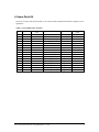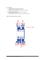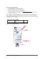
1
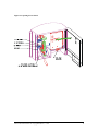
ICS-200B Service Manual
EVI, Inc.
Electric Vehicle Infrastructure, Inc.
Copyrighted Material
Revision History, SERVICE MANUAL 01.DOC
Date
Revision
Author
Comment
3/23/1998
1.0a
Jason France
First Draft
3/30/1998
1.0b
Jason France
Changes from first presentation to
Table 5-2, added comments to the 10 EV
Data Log Sheet
1/11/1999
1.0c
Mickey Oros
First Draft for "B" unit
ICS-200B Service Manual
Electric Vehicle Infrastructure Inc. Copyrighted Material, 1/19/99
1
Table of Contents
1. ABOUT THIS DOCUMENT
1.1. SCOPE
1.2. COMMENTS
5
5
5
2. ABBREVIATIONS AND TERMS
6
3. SERVICE EQUIPMENT
8
4. SPARE PARTS KIT
9
5. TROUBLE SHOOTING
5.1. GROUND FAULT ERROR
5.2. SERVICE GROUND NOT PRESET
5.3. REAL TIME CLOCK NOT COUNTING
5.4. VENTING FAN FAILURE
5.5. EV CABLE PULLED FREE
5.6. CONTACTOR OPEN, FAILURE 00
5.7. CONTACTOR CLOSED, FAILURE 01
5.8. ELECTRIC VEHICLE CONNECTION FAULT
5.9. EV CABLE TENSION
5.10. SYSTEM NOT RESPONDING
5.11. PILOT +12V CIRCUITRY, FAILURE 03
5.12. PILOT -12V CIRCUITRY, FAILURE 04
5.13. CONFIGURATION CASE 1, FAILURE 05
5.14. GFCI CIRCUITRY, FAILURE 06
5.15. CONFIGURATION CASE 2
5.16. CONTACTOR DRIVER, FAILURE 07
5.17. NO WDT TRIPS
5.18. EXCESSIVE EV CURRENT
6. INSPECTING COMPONENTS
6.1. INSPECTING FUSES
6.2. INSPECTING CONTACTOR
6.3. INSPECTING POWER SUPPLY
6.4. INSPECTING ANDERSON CONNECTORS
6.5. INSPECTING PCB
6.6. INSPECTION FOR PROPER GROUND
ICS-200B Service Manual
Electric Vehicle Infrastructure Inc. Copyrighted Material, 1/19/99
11
13
13
13
14
14
14
15
15
15
16
16
16
17
17
17
18
18
18
19
19
19
20
20
20
21
2
7. PROGRAMMING NEW PCB USING MAGMA
22
8. REPLACING COMPONENTS
23
8.1. OPENING THE ENCLOSURE
8.2. PRINTED CIRCUIT BOARD
8.3. CONTACTOR
8.4. POWER SUPPLY
23
25
26
27
9. USING THE DATA SWITCH
28
9.1. INITIATING THE DATA LOG ANNOUNCEMENT
9.2. RECORDING THE DATA LOG
9.3. CLEARING THE DATA LOG
10. EVI DATA LOG SHEET
ICS-200B Service Manual
Electric Vehicle Infrastructure Inc. Copyrighted Material, 1/19/99
28
28
28
29
3
Table of Tables
Table 2-1 List of Abbreviations and Terms __________________________________________________ 6
Table 3-1 Required Equipment ___________________________________________________________ 8
Table 3-2 Extended Service Equipment _____________________________________________________ 8
Table 4-1 ICS-200-B, Spare Parts Kit ______________________________________________________ 9
Table 4-2 Mounting Hardware ICS-200-B _________________________________________________ 10
Table 5-1 Symptoms Based on Protection and Service for Trouble Shooting _______________________ 12
Table 5-2 Symptoms Based on Data Log for Trouble Shooting__________________________________ 12
Table 7-1 Installing a New PCB _________________________________________________________ 22
Table 7-2 Installing a New PCB if the Old One Does Not Work _________________________________ 22
Table 8-1 Power Supply Compatible Group #1 ______________________________________________ 27
Table 9-1 Starting the Data Log _________________________________________________________ 28
Table 10-1 First Message Sequence_______________________________________________________ 29
Table 10-2 Second Message Sequence_____________________________________________________ 29
Table of Figures
Figure 8-1
Figure 8-2
Figure 8-3
Figure 8-4
Figure 8-5
Removing Beauty Cover_______________________________________________________ 23
Opening Back Service Panel ___________________________________________________ 24
Removing PCB ______________________________________________________________ 25
Wiring Connections for Contactor_______________________________________________ 26
Power Supply Connections ____________________________________________________ 27
ICS-200B Service Manual
Electric Vehicle Infrastructure Inc. Copyrighted Material, 1/19/99
4
1. About This Document
1.1. Scope
A summary of how to access records and interprets the ICS-200 verbal diagnostics for the purpose of
service. Information about what to do given certain failures and symptoms.
1.2. Comments
The service manuals intent is to lend a hand to maintenance personnel in diagnosing and repairing filed
units. Also, to assist in establishing when a suspicious behavior is not a failure.
The ICS-200 includes an internal diagnostics data logging system which is maintained by the backup
battery. Often times, problems can be determined by analyzing this data log.
ICS-200B Service Manual
Electric Vehicle Infrastructure Inc. Copyrighted Material, 1/19/99
5
2. Abbreviations and Terms
Like any market, the Electric Vehicle products have their own set of new terminology. Table 2-1 will
help you understand some of the terms associated with Electric Vehicles and EVI’s ICS-200 product
series.
Table 2-1 List of Abbreviations and Terms
Abbreviation
Description
Charging Station
general term for the ICS-200 product, also EVSE, HBCD, or
PCS
A mechanical and electrical interconnecting scheme for the
purpose of transferring electrical energy using conductive
contacts which are physically mated
A high power switching device similar to a relay. Its purpose
is to provide control of EV cable energization.
Small device which connects to the ICS-200’s FICS adapter
port, used for ICS-200 data gathering
Electric Vehicle
Electric Vehicle Service Equipment, general term for the ICS200 product, also HBCD, Charging Station or PCS
A pulling force on the cable when experience by the system
results in de-energization of the circuit conductors of the cable
Field Installation and Configuration System, a device which
connects PC computer to the ICS-200
Ground Fault Circuit Interrupter, a device which detects small
amounts of ground current in an AC system and is capable of
de-energizing the contactor if a threshold current is present
Ground Fault Coil, a toroid sensor through which the L1 and
L2 conductors are routed, used to sense ground fault currents
Home Based Connection Device, general term for the ICS-200
product, also EVSE, Charging Station or PCS
The product name for EVI’s line of level 2 EVSE
A power rating as defined by SAE-J1772 which specifies a
maximum of 240VAC and 48Amps
Load Management, a controlling mechanism by which the
utility can govern when electric energy will be consumed by
the EVSE
Software used in conjunction with the FICS Adapter for
diagnostics and configuration of the ICS-200
Printed Circuit Board, the circuitry card inside of the ICS-200
which performs most of the EVSE functions
Power Control Station, general term for the ICS-200 product,
also EVSE, Charging Station or HBCD
Portable EVSE Tester, EVI test equipment used to verify
EVSE functionality
A pulse width modulated signal used to communicate
information between the EVSE and the EV
Conductive Coupling
Contactor
Data Switch
EV
EVSE
Excessive Pressure
FICS Adapter
GFCI
GFCI Coil
HBCD
ICS-200
Level 2
LM
Magma
PCB
PCS
PET
Pilot Signal
ICS-200B Service Manual
Electric Vehicle Infrastructure Inc. Copyrighted Material, 1/19/99
6
Abbreviation
Description
Pull-free
The mechanism by which a cable is allowed to disengage from
a connection device when it experiences certain forces
Switching Power Supply, the electronics package inside of the
ICS-200 which converts AC power to power for the printed
circuit board
A venting fan will be placed in enclosed installations where
batteries which vent hazardous gases will be charged.
Speech based on the concatenation of recorded words and
phrases for the communication of system status
SPS
Venting Fan
Verbal Announcer
(VA)
ICS-200B Service Manual
Electric Vehicle Infrastructure Inc. Copyrighted Material, 1/19/99
7
3. Service Equipment
Table 3-1 Required Equipment
•
SAE wrench set or equivalent, Phillips head screwdriver, and T-15 & 27 Torx
wrench
•
Data Switch and blank data log sheets
•
•
DMM, or Digital Multi-meter capable of measuring RMS AC Volts, DC Volts
and resistance
PET, Portable EVSE Tester, available from EVI
•
Spare Parts Kit, available from EVI
Table 3-2 Extended Service Equipment
•
FICS Adapter, Field Installation and Configuration System, available from EVI
•
Laptop running Windows 95 or 3.11, 800x600 screen, 8MB, Free serial port
•
Magma Software loaded onto laptop, available from EVI or
http:\\www.evii.com
ICS-200B Service Manual
Electric Vehicle Infrastructure Inc. Copyrighted Material, 1/19/99
8
4. Spare Parts Kit
Stock one set of the items listed in Table 4-1 for each 100 units installed in the field for optimum service
capabilities.
Table 4-1 ICS-200-B, Spare Parts Kit
Item #
Qty per Unit
1
1
Mfgr
P/N
200010-C-3
Description
Value
Assembly, PCB
PCB
Fill
Order
1
2
1
STRAIN
Strain Detection Module
PCB
3
1
SQD8910DA53V09
Contactor, 220V, 50 amp
3 pole
1
1
4
1
MAP40-3003
Power Supply
40 watt
1
5
1
DC32WA
Speaker, waterproof, 3.5"
4 watt
1
6
1
CR2016
BATTERY, COIN
3V LITHIUM
1
7
3
31333003
Fuse, 3AG
3 amp
20
8
1
OA-50-QC
Thermostat
< 32deg F
1
9
14
RAD18277
Crimp Terminals, Q-C
1/4", fem
ASSORT
10
6
RAD2573
Crimp Terminals, Q-C
3/16"", fem
ASSORT
11
2
1300G3
Slip Conn, w/pin, Red
75 amp
1
12
2
1300G4
Slip Conn ,w/pin, Black
75 amp
1
13
2
1300G2
Slip Conn ,w/pin, Green
75 amp
1
14
2
1395G4
Slip Conn, w/pin, Blue
15 amp
2
15
2
1395G5
Slip Conn, w/pin, Yellow
15 amp
2
16
2
1395G6
Slip Conn, w/pin, Orange
15 amp
2
17
2
1395G7
Slip Conn, w/pin, Gray
15 amp
2
ICS-200B Service Manual
Electric Vehicle Infrastructure Inc. Copyrighted Material, 1/19/99
9
Table 4-2 is included as a reference in case ICS-200-B mounting hardware is misplaced during servicing.
Use this table as a guide when replacing nuts, bolts, washers, etc.
Table 4-2 Mounting Hardware ICS-200-B
Enclosure to Wall
A. 1/4 x 2 1/2” Long Hex Head Lag Screw Zinc
B. 1/4” Seal Bonding Washer
C. 3/4" Water Tight NEMA Fitting
(Qty = 4)
(Qty = 4)
(Qty = 1)
Single Enclosure-to Post *
A. Single Support Post Package
(Qty = 1)
Dual Enclosure to Post **
A. Single Support Post Package
B. Dual Support Accessory Package
(Qty = 1)
(Qty = 1)
* Single Support Post Package
A. Post with Base
• 5/8-11 Hex Nut Zinc
• 5/8 Washer
B. Base Cover
• #6-32 x 1/2” Flat Head Phillips Screw
C. Mounting Plate
D. Single Support Bracket
E. Top Cap (Single has 3 flanges)
F. 3/4" Conduit Assembly
G. 1/4-20 x 1.0” Torx (T-27) Screw
H. 1/4” Seal Bonding Washer
I. 1-1/8" Plug
(Qty = 1)
(Qty = 8)
(Qty = 8)
(Qty = 2)
(Qty = 4)
(Qty = 1)
(Qty = 1)
(Qty = 1)
(Qty = 1)
(Qty = 10)
(Qty = 10)
(Qty = 1)
** Dual Support Accessory Package
A.
B.
C.
D.
E.
F.
Mounting Plate
Dual Support Brackets
Top Cap (Dual has 2 flanges)
3/4" Conduit Assembly
1/4-20 x 1.0” Torx (T-27) Screw
1/4” Seal Bonding Washer
ICS-200B Service Manual
Electric Vehicle Infrastructure Inc. Copyrighted Material, 1/19/99
(Qty = 1)
(Qty = 2)
(Qty = 1)
(Qty = 1)
(Qty = 10)
(Qty = 10)
10
5. Trouble Shooting
Table 5-1 are intended to help with determining which ICS-200 component may be malfunctioning in a
failed unit. After establishing the possible source of problem, use the procedures in section 6 Inspecting
Components to check component for failure.
Step 1. Use Trouble Shooting section to focus on possible component failure
Step 2. Use Inspecting section to verify the suspect component has failed
The ICS-200 has many features to help diagnose problems. However, to take advantage of these features
it is necessary to:
LOOK, LISTEN, and GET the DATA LOG.
Often times, simply making a conscious effort to take note of what the unit is trying to say, will point
directly to the problem area.
•
Look at the FRONT panel, make note of which designators are lit
•
If the unit is making an announcement, make note of exact message
•
Press the STOP BUTTON, Listen to the announcement,
ICS-200B Service Manual
Electric Vehicle Infrastructure Inc. Copyrighted Material, 1/19/99
11
Table 5-1 Symptoms Based on Protection and Service for Trouble Shooting
Designator
Action
Announcement
Condition
Protection
Protection
Protection
Service
Blinking
Static
Static
Static
“Ground Fault Error Since time”
“Please Reduce Cable Tension”
“Ground Not Connected Since time”
Service
Service
Service
Service
Service
Service
Service
Service
Service
Service
Service
Static
Static
Static
Static
Static
Static
Static
Static
Static
Static
Static
Rotating
Any
always
any
“Fan Failure Since time”
“System Failure 00 Since time”
“System Failure 01 Since time”
“System Failure 02 Since time”
“System Failure 03 since time”
“System Failure 04 since time”
“System Failure 05 since time”
“System Failure 06 since time”
“System Failure 07 since time”
“System Failure 08 since time”
“Electric Vehicle Connection Fault
Since time”
No Activity After Service Power
Ground Fault
Ground Fault
EV Cable Tension
Service Ground Not
Present
Venting Fan Failure
Contactor Open
Contactor Closed
EV Cable Pulled Free
Pilot +12V Circuitry
Pilot 12V Circuitry
Configuration Case 1
GFCI Circuitry
Contactor Driver
RTC Not Counting
Pilot Voltage Out Of
Specifications
Configuration Case 2
System Not
Responding
Section
Reference
5.1
5.1
5.9
5.2
5.4
5.6
5.7
5.5
5.12
5.11
5.13
5.14
5.16
5.3
5.8
5.15
5.10
Table 5-2 Symptoms Based on Data Log for Trouble Shooting
Data Log
00
01
02
03
04
05
06
07
08
09
10
11
12
13
14
15
Condition
Contactor Stuck Open
Contactor Stuck Closed
Cable Pull Free
Pilot Positive 12V
Pilot Negative 12V
Configuration WDT
GFCI Circuitry
Dual Contactor Driver
RTC Not Counting
No WDT Resets
GFCI Trips
Pilot Dead Band
Venting Fan
EV Excessive Current
Service Ground Missing
Incorrect Time or Date
Section
Reference
5.6
5.7
5.5
5.12
5.11
5.13
5.14
5.16
5.3
5.17
5.1
5.8
5.4
5.18
5.2
5.3
5.1. Ground Fault Error
The ground fault system is capable of automatic re-closure. The protection designator will blink and
the EV cable will be de-energized during a ground fault condition. After the ICS-200 has attempted to
re-start the charging cycle several times, it will cease re-closure and the designator will remain
ICS-200B Service Manual
Electric Vehicle Infrastructure Inc. Copyrighted Material, 1/19/99
12
statically lit. The announcer will then periodically repeat the error message, including the time of the
first occurrence of the failure. The delivered units are configured to attempt re-closure 5 times with 15
minute intervals in-between.
Actions to Take
1. If there is a ground fault present on the EV, this is a normal operation
2. Use the PET to test the ICS-200’s ground fault circuitry
Suspected Components
1. Ground Fault Coil
2. Black and White wires from the ground fault coil to the PCB connector
3. Circuitry on the PCB
5.2. Service Ground Not Preset
If the ground from the service panel is not present, and there are no other paths to earth ground, the
system will cease charging and enter a service required failure mode. Conductive charging stations
require a bonded ground as a primary means of providing personal safety. See the document Proper
Service Connection in the service pack.
Actions to Take
1. 6.6 Inspection for Proper Ground
Suspected Components
1. Improper service connection
2. #8 Green bonding wire from the junction box into the internal ground block
3. Small green wires on the internal ground block
5.3. Real Time Clock Not Counting
The ICS-200 charging cycles are based on the internal clock, it must operate correctly for proper
operation. The internal clock incorporates a battery backup capable of 10 years of non-powered
operation.
Actions to Take
1. 6.5 Inspecting PCB
Suspected Components
1. Circuitry on the PCB
ICS-200B Service Manual
Electric Vehicle Infrastructure Inc. Copyrighted Material, 1/19/99
13
5.4. Venting Fan Failure
The ICS-200 incorporates circuitry for monitoring the proper operation of the venting fan. If the
venting fan is required but not operating properly, the unit will disallow charging and enter this failure
mode. The venting fan is powered from L1 and Neutral. The venting fan must be serviced.
Actions to Take
1. Use the PET to test the ICS-200’s charging with FAN operation
2. When powered by the ICS-200, check the venting FAN
Suspected Components
1. Circuitry on the PCB
2. Improper wiring in the junction box
3. Improper or no Neutral write from the service panel
5.5. EV Cable Pulled Free
The ICS-200 can detect when the EV cable has been pulled free from the unit. The unit will not
operate until the cable is re-installed.
Actions to Take
1. Inspect the pull free plate for problems
2. Inspecting Anderson Connectors
Suspected Components
1. Circuitry on the PCB
2. The small GREY Anderson connector in the pull free mechanism
5.6. Contactor Open, Failure 00
The ICS-200 can detect when the EV connector is not energized when it should be. This condition is a
result of a failed power contactor. The unit will not operate until the contactor is repaired.
Actions to Take
1. 6.1 Inspecting Fuses
2. 6.2 Inspecting Contactor
Suspected Components
1. Blown fuse
2. Disconnected or loose quick connect on the contactor
3. Contactor’s energizing coil or contacts has gone bad
4. Circuitry on the PCB
ICS-200B Service Manual
Electric Vehicle Infrastructure Inc. Copyrighted Material, 1/19/99
14
5.7. Contactor Closed, Failure 01
The ICS-200 can detect when the EV connector is energized when it should not be. This condition is a
result of a failed power contactor. The unit will not operate until the contactor is repaired.
Actions to Take
1. 6.1 Inspecting Fuses
2. 6.2 Inspecting Contactor
Suspected Components
1. Blown fuse
2. Disconnected or loose quick connect on the contactor
3. Contactor’s energizing coil or contacts has gone bad
4. Circuitry on the PCB
5.8. Electric Vehicle Connection Fault
The ICS-200 can detect when the EV is manipulating the pilot incorrectly. This condition is a result of
a failed ICS-200 pilot driver circuit, connection, or EV pilot circuitry. Inspect the connector and try to
re-enter a charging cycle.
Actions to Take
1. Inspect the EV’s inlet for debris
2. Inspect the EVSE connector for debris
3. Inspecting Anderson Connectors
4. Use the PET to test the ICS-200
Suspected Components
1. The small BLUE Anderson connector in the pull free mechanism
2. Circuitry on the PCB
5.9. EV Cable Tension
It is important not to pull too hard on the EV cable. The ICS-200 is equipped with a pull-free system
which allows the EV cable to come out of the unit under conditions which may cause damage to the
EV or the ICS-200. Release tension on the EV cable.
Actions to Take
1. Inspect the cable for inadvertent sources of strain
2. Inspect the Excessive Strain PCB’s optical sensors for debris
3. Inspect the pull free plate for problems
Suspected Components
1. Excessive Strain PCB
2. Loose or broken wires on the Excessive Strain PCB
3. Circuitry on the Main PCB
ICS-200B Service Manual
Electric Vehicle Infrastructure Inc. Copyrighted Material, 1/19/99
15
5.10. System Not Responding
In the unlikely event the ICS-200 were to discontinue responding at all, power the system down using
the circuit breaker for 10 seconds, then re-apply power. The ICS-200 incorporates circuitry that
maintains a condition of safety even if the internal CPU were to malfunction.
Actions to Take
1. Press the STOP button and check for announcement
2. Check for service power to the junction box
3. 6.1 Inspecting Fuses
4. 6.3 Inspecting Power Supply
5. 6.5 Inspecting PCB
Suspected Components
1. No power from service
2. Power supply failed
3. No connection to front panel
4. Circuitry on the Main PCB
5.11. Pilot +12V Circuitry, Failure 03
The ICS-200 can detect when the EV pilot signal positive voltage sensing circuitry is not functioning
correctly. The unit will not operate until the circuitry is repaired.
Actions to Take
1. Use the PET to test the ICS-200
2. Inspecting Anderson Connectors
Suspected Components
1. The small BLUE Anderson connector in the pull free mechanism
2. Short in the wiring harness
3. Circuitry on the Main PCB
5.12. Pilot -12V Circuitry, Failure 04
The ICS-200 can detect when the EV pilot signal negative voltage sensing circuitry is not functioning
correctly. The unit will not operate until the circuitry is repaired.
Actions to Take
1. Use the PET to test the ICS-200
2. Inspecting Anderson Connectors
Suspected Components
1. The small BLUE Anderson connector in the pull free mechanism
2. Short in the wiring harness
3. Circuitry on the Main PCB
ICS-200B Service Manual
Electric Vehicle Infrastructure Inc. Copyrighted Material, 1/19/99
16
5.13. Configuration Case 1, Failure 05
The ICS-200 requires certain internal programmable registers to be set to the correct values. If the
values are incorrect, they will be re-programmed automatically. This condition is only a problem if it
persists.
Actions to Take
1. 6.5 Inspecting PCB
Suspected Components
1. Circuitry on the Main PCB
5.14. GFCI Circuitry, Failure 06
The ICS-200 can detect when the ground fault sensing circuitry is not functioning correctly. The unit
will not operate until the circuitry is repaired. This circuitry is used each time the EV is connected.
Actions to Take
1. Use the PET to test the ICS-200’s ground fault circuitry
Suspected Components
1. Ground Fault Coil
2. Black and White wires from the ground fault coil to the PCB connector
3. Green wire from the PCB connector through the GFCI coil to the internal grounding block
4. Circuitry on the PCB
5.15. Configuration Case 2
The ICS-200 has 4 programmable sub-systems; Embedded Software, On-site and Load Management,
Factory, and Voice Data Bank. When the service power is applied to the system, these 4 memories will
be checked for integrity and compatibility. If this failure occurs, it is most likely the ICS-200 has been
programmed incorrectly. If the unit has not been recently programmed, the system must be repaired.
Actions to Take
1. 6.5 Inspecting PCB
2. Re-program the unit using Magma
Suspected Components
1. Circuitry on the Main PCB
ICS-200B Service Manual
Electric Vehicle Infrastructure Inc. Copyrighted Material, 1/19/99
17
5.16. Contactor Driver, Failure 07
The ICS-200 can detect when the EV connector is energized when it should not be. This condition is a
result of a failed driver circuitry. The unit will not operate until the contactor is repaired.
Actions to Take
1. 6.5 Inspecting PCB
2. 6.2 Inspecting Contactor
Suspected Components
1. Circuitry on the Main PCB
2. Contactor’s energizing coil or contacts has gone bad
5.17. No WDT Trips
The ICS-200 can detect when its either of its two CPU monitoring circuits has failed. The unit will not
operate until the contactor is repaired.
Actions to Take
1. 6.5 Inspecting PCB
Suspected Components
1. Circuitry on the Main PCB
5.18. Excessive EV Current
The ICS-200 can detect when the EV is drawing more current than the branch circuit is configured to
handle. This safety feature is programmable using Magma. This condition is only a problem if it
persists.
Actions to Take
1. 6.5 Inspecting PCB
2. Check the EV current coil, a small toroid which has the red L1 passing through it
Suspected Components
1. Circuitry on the Main PCB
ICS-200B Service Manual
Electric Vehicle Infrastructure Inc. Copyrighted Material, 1/19/99
18
6. Inspecting Components
Table 5-1 is intended to help with determining which ICS-200 component may be malfunctioning in a
failed unit. After establishing the possible source of problem, use the procedures in section 6 Inspecting
Components to check component for failure.
Step 1. Use Trouble Shooting section to focus on possible component failure
Step 2. Use Inspecting section to verify the suspect component has failed
6.1.
1.
2.
3.
4.
5.
6.
Inspecting Fuses
Turn off the power to the unit at the circuit breaker
Open the enclosure as described in section 8.1
Check the fuses by gently pulling on them
Use a DMM measure the resistance of each FUSE
All fuses should read about 0 ohms of resistance
Replace any fuses which are blown
6.2.
1.
2.
3.
4.
5.
6.
7.
8.
9.
10.
11.
12.
13.
14.
15.
16.
17.
Inspecting Contactor
Turn off the power to the unit at the circuit breaker
Open the enclosure as described in section 8.1
Check the quick connects and wires connected to the contactor by gently pulling on them
Turn on the power to the unit at the circuit breaker
Use the DMM to measure the voltage on the contactors energizing coil across the 2 yellow wires
When the contactor is off, this should read about 0 VAC
When the contactor is on, this should read over 200 VAC
Turn on the power to the unit at the circuit breaker
Use the DMM to measure the voltage on the contactors input
Measure across the Red and Black number #8 coming from the conduit
This should always read 200 VAC
Use the PET or EV to put the ICS-200 into the charging mode
Listen to hear the contactor close
Use the DMM to measure the voltage on the contactors output
Measure across the Red and Black number #8 going to the Anderson connectors
When the contactor is off, this should read about 0 VAC
When the contactor is on, this should read over 200 VAC
ICS-200B Service Manual
Electric Vehicle Infrastructure Inc. Copyrighted Material, 1/19/99
19
6.3.
1.
2.
3.
4.
5.
6.
7.
Inspecting Power Supply
Refer to Figure 8-5
Open the enclosure as described in section 8.1
Use the DMM to measure the AC voltage on the Power Supply’s input
Measure across the two black wires
This should read over 200 VAC
Use the DMM to measure the DC voltage on the Power Supply’s output, to chassis ground
The following measurements should be read:
From
To
Orange
White
Red
Red
Black
Black
Black
Black
Approximate
DC Voltage
+15 VDC
-15 VDC
+5 VDC
+5 VDC
6.4.
1.
2.
3.
4.
5.
6.
7.
8.
9.
Inspecting Anderson Connectors
Turn off the power to the unit at the circuit breaker
Open the enclosure as described in section 8.1
Make sure the Anderson connectors are firmly seated
Check for matching colors
Anderson internal contacts may come loose
Check the internal contacts by gently pulling the wires
Check the internal contacts by gently pushing the wires into the plastic holders
It is possible for the contact crimps to fail
Check for failed contacts by measuring the resistance from inside the connector to the other end of
the wire, wherever it lands
6.5.
1.
2.
3.
4.
5.
Inspecting PCB
Open the enclosure as described in section 8.1
Look for the “heart beat”, a blinking read light at the bottom of the PCBG
Turn off the power to the unit at the circuit breaker
Make sure the PCB is firmly seated into the connector
Inspect the PCB for physical damage, such as blown up parts or debris
6.6. Inspection for Proper Ground
1. Open the junction box
2. The following measurements should be read:
From
To
L1
L1
L2
L1
L2
Ground
L2
Ground
Ground
Neutral (if used)
Neutral (if used)
Neutral (if used)
Approximate
AC RMS Voltage
208 to 240VAC
120VAC
120VAC
120VAC
120VAC
Less than 15VAC
ICS-200B Service Manual
Electric Vehicle Infrastructure Inc. Copyrighted Material, 1/19/99
20
7. Programming New PCB Using Magma
When a new PCB is installed in an ICS-200-B, it must programmed to the configuration of the previously
installed PCB. It is necessary to use Magma and the FICS adapter to accomplish this task.
As is often the case, a failed PCB will still communicate properly with the Magma software. In this case,
use the steps outlined in Table 7-1.
If a failed board will not respond at all to the Magma software, use the steps outlined in Table 7-2.
Table 7-1 Installing a New PCB
1.
2.
3.
4.
5.
6.
7.
8.
9.
10.
11.
12.
13.
14.
15.
16.
17.
Before removing failed PCB
From Magma, go to File -> Download Parameters From ICS…
Check all three Paramsets
Click on Download
Wait for download to complete, this takes about 1 minute
Now, Magma holds the configuration of the original PCB
Save the configuration into a file
Select File -> Save As …
Choose a file name, and do not forget it
Change the PCB as described in section 8.2
Load the saved configuration
Select File -> Open …
Choose the file name from step 9 then click on OK
Select File -> Upload Parameters To ICS
Check the three Paramsets, OSLM, Factory, and NVRAM
Click on Upload
Wait for upload to complete, this takes about 2 minutes
Table 7-2 Installing a New PCB if the Old One Does Not Work
1.
2.
3.
4.
5.
6.
7.
8.
Change the PCB as described in section 8.2
Load the configuration
Select File -> Open …
Choose the file name based on the EVI part number desired
Select File -> Upload Parameters To ICS …
Check the three Paramsets, OSLM, Factory, and NVRAM
Click on Upload
Wait for upload to complete, this takes about 2 minutes
ICS-200B Service Manual
Electric Vehicle Infrastructure Inc. Copyrighted Material, 1/19/99
21
8. Replacing Components
8.1.
1.
2.
3.
Opening the Enclosure
Remove and retain (2) ¼-15 Torx left side, Figure 8-1
Swing box open by pulling on the left side
When replacing screws on the door, DO NOT OVER-TIGHTEN
Figure 8-1 Opening Service Door
ICS-200B Service Manual
Electric Vehicle Infrastructure Inc. Copyrighted Material, 1/19/99
22
Figure 8-2 Opening Service Panel
ICS-200B Service Manual
Electric Vehicle Infrastructure Inc. Copyrighted Material, 1/19/99
23
8.2.
1.
2.
3.
4.
5.
6.
7.
8.
9.
Printed Circuit Board
Turn circuit breaker off, verify no power is applied
Open the enclosure as described in section 8.1
Pull each corner of the PC board gently off the 4 Snap-top standoffs.
Pull PCB off the header approximately a ½ inch, this will pull it away from connector
Pull PCB out, holding by the metal head sink on top
Remove Push Button connector cable from back side of board
When replacing, pop back on posts
When replacing, REMEMBER TO CONNECT Push Button connector cable on back side of board
New PCB’s MUST BE PROGRAMMED with a new configuration, see section 7
Figure 8-3 Removing PCB
Hold Board ONLY
By Metal Heat Sink
Other Side
*** NOTE ***
LED's must face out
Pull header off
approximately 1/2"
Pull each corner on the board gently from
the 4 Snap-top standoffs.
Header
ICS-200B Service Manual
Electric Vehicle Infrastructure Inc. Copyrighted Material, 1/19/99
24
8.3.
1.
2.
3.
4.
5.
6.
7.
Contactor
Turn circuit breaker off, verify no power is applied
Open the enclosure as described in section 8.1
Carefully observe the placement of wires, illustrated in Figure 8-4
Remove the #8 power wiring first
Remove the quick connects, DO NOT GRIP BY THE WIRES
Remove and retain (4) #8-32 nuts
When replacing the contactor, carefully observe the placement of wires
Figure 8-4 Wiring Connections for Contactor
ICS-200B Service Manual
Electric Vehicle Infrastructure Inc. Copyrighted Material, 1/19/99
25
8.4.
1.
2.
3.
4.
5.
Power Supply Replacement
Turn circuit breaker off, verify no power is applied
Open the enclosure as described in section 8.1
Remove the two connectors, AC Power and PCB Power
Remove power supply from the snap-top stand-offs posts.
When replacing the power supply, make sure the green terminal is BETWEEN the power supply
and the metal mounting post
ONLY replace power supply with compatible type. Use Table 8-1 to determine if the replacement power
supply is compatible with the ICS-200-B wiring harness. Currently, there are two groups of compatible
power supplies used in the ICS-200-B. If the replacement power supply is in the same group as the original
power supply, then they are compatible.
Table 8-1 Power Supply Compatible
Part Number
Manufacturer
Use
MAP40-3003
Power One
common
Figure 8-5 Power Supply Connections
ICS-200B Service Manual
Electric Vehicle Infrastructure Inc. Copyrighted Material, 1/19/99
26
9. Using the Data Switch
Before attempting to collect the data log using the Data Switch, it is important that copies of the EVI
Data Log Sheet in section 10 are available for recording the announced information on.
9.1. Initiating the Data Log Announcement
The data switch is used to gather ICS-200 event and usage information.
Table 9-1 Starting the Data Log
1.
2.
3.
4.
5.
6.
7.
Insert the Data Switch into the FICS port, located inside on the PC board
Press and HOLD the Data Switch button
Press and HOLD the Start and Stop button
Release the Data Switch button
Continue to HOLD the Start and Stop buttons until unit begins to speak
As soon as “kilo-watt-hours” is spoken, release the Start and Stop buttons
Record spoken information into the EVI Data Log Sheet
9.2. Recording the Data Log
The data log announcement will follow the form listed in section 10. In each place where the sheet is
blank, there ICS-200 will speak a number. Write the numbers down as they are spoken.
Note that the numbers which are longer than 2 digits are spoken in-groups of two digits. For example,
the number “12345” will actually be spoken as “01”, “23”, “45”. Simply record the groups of 2
digits as they are heard and make sense of the numbers after the data log is done.
9.3. Clearing the Data Log
After announcement of the durability constraints and error log, “Press stop to cancel set failure to zero”
will be announced.
Press the STOP button to continue normal operation without clearing the error log.
Press CHARGE NOW to continue. “Press stop to cancel set failure to zero” will be announcement again.
Press STOP to abort. Press CHARGE NOW again to clear the error log.
The durability constraint counts cannot be cleared from the front panel.
ICS-200B Service Manual
Electric Vehicle Infrastructure Inc. Copyrighted Material, 1/19/99
27
10.EV Data Log Sheet
Use the following tables to record the error information from the ICS-200.
Table 10-1 First Message Sequence
Durability Constraint
Count
“kilo-watt hours”
“connection”
“charged”
“reduce cable tension”
Table 10-2 Second Message Sequence
Failure
Number
“failure”
“failure”
“failure”
“failure”
“failure”
“failure”
“failure”
“failure”
“failure”
“failure”
“failure”
“failure”
“failure”
“failure”
“failure”
“failure”
“failure”
Count
“is”
“is”
“is”
“is”
“is”
“is”
“is”
“is”
“is”
“is”
“is”
“is”
“is”
“is”
“is”
“is”
“is”
Month
Day
Year
“at”
“at”
“at”
“at”
“at”
“at”
“at”
“at”
“at”
“at”
“at”
“at”
“at”
“at”
“at”
“at”
“at”
To Clear The Log
1.
2.
3.
4.
5.
6.
“Press stop to cancel set failure to zero” announced.
Press the STOP button to continue normal operation without clearing the error log.
Press CHARGE NOW to continue.
“Press stop to cancel set failure to zero” will be announcement again.
Press STOP to abort.
Press CHARGE NOW again to clear the error log.
ICS-200B Service Manual
Electric Vehicle Infrastructure Inc. Copyrighted Material, 1/19/99
28