1
5500A
Service Manual
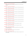
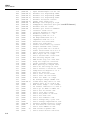
Edge Frequency function
Verification, 6-35, 6-92
Edge function
adjusting aberrations, 6-117
adjusting the rise time, 6-122
Rise time verification, 6-36, 6-93
Theory of Operation, 6-12, 6-72
Edge Function
Specifications, 6-7, 6-69
Trigger Specifications, 6-11
Encoder assembly (A2)
Theory, 2-4
Equipment required for calibration and verification,
3-3
Error messages
Diagnostic, 4-7
Non diagnostic, 4-14
SC Option not installed, 6-5, 6-67
—F—
Frequency specifications, 1-24
Fuses, internal, 4-14
—G—
General specifications, 1-6
—H—
Hardware adjustments for SC300, 6-111
Hardware adjustments for SC300 Option, 6-115
Hardware adjustments for SC600, 6-60
Harmonics (2nd - 50th) specifications, 1-25
—L—
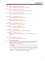
Leveled Sine Wave function
adjusting the harmonics, 6-62, 6-116
adjusting VCO balance, 6-61, 6-115
Amplitude Verification, 6-40, 6-96
equipment setup, 6-23, 6-82
Flatness Verification
High frequency, 6-25, 6-83
High frequency at 5.5 V, 6-102
High frequency at 5.5V, 6-46
Low frequency, 6-24, 6-83
Low frequency at 5.5 V, 6-102
Low frequency at 5.5V, 6-46
Low frequency equipment setup, 6-40, 6-44,
6-96, 6-100
Frequency Verification, 6-41, 6-97
Harmonics Verification, 6-42, 6-98
Theory of Operation, 6-12, 6-72
Leveled Sine Wave Function
Specifications, 6-8, 6-70
2
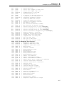
—M—
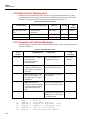
Main CPU assembly (A9)
Theory, 2-8
MeasZ Capacitance
Verification, 6-58
MeasZ function
Calibration, 6-26
MeasZ Function
Capacitance Specifications, 6-11
Resistance Specifications, 6-11
MeasZ Resistance
Verification, 6-57
—O—
Overload function
Verification, 6-59
Overload Function
Specifications, 6-12
—P—
Performance verification. See Verification
Phase specifications, 5500A, 1-21
Power and dual output limit specifications, 1-21
Power supplies, 2-8
Inguard supplies, 2-8
Outguard supplies, 2-8
Pulse Function
Trigger Specifications, 6-10
Pulse Generator Function
Specifications, 6-10
Pulse period verification, 6-57
Pulse Width function
Calibration, 6-25
equipment setup, 6-25
Verification
equipment setup, 6-56
Pulse width verification, 6-56
—R—
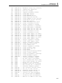
Remote commands for calibration, 3-16
Removing
Analog modules, 4-3
Rear panel assemblies, 4-4
The Encoder (A2) and Display PCAs, 4-4
The Filter PCA (A12), 4-4
The Keyboard and Accessing the Output Block,
4-4
The Main CPU (A9), 4-3
Reports, calibration, 3-18
Required equipment for calibration and verification,
3-3
Resistance specifications, 1-9