1
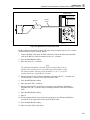
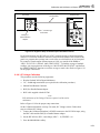
SC300 Option
Theory of Operation
6
The 5 s to 50 ms markers are generated on the A6 DDS board and are passed to the A50
board. The signal path is also split to drive the external trigger circuitry on the A50
board. If turned on, the trigger is connected to the Trig Out BNC on the front panel. The
marker signal passing through the A50 board is connected up to the attenuator assembly.
The signal is then passed to the SCOPE connector BNC on the front panel.
The 20 ms to 2 ns markers are generated on the A50 board. From 20 ms to 100 ns, a 20%
duty cycle square wave is produced in addition to the spike and square wave markers.
From 50 ns to 20 ns, only spike or square waves are produced. At 10 ns, the user can
chose between the square wave or the leveled sine signal. The marker signal is passed
from the A50 board to the attenuator assembly and then to the SCOPE connector BNC
on the front panel.
The trigger signal is also generated on the A50 board. If the trigger is turned on, the
signal is connected to the Trig Out BNC on the front panel.
6-98. Wave Generator Mode
All signals for the wavegen function are generated from the A6 board and are passed to
the A50 board. They are then sent to the attenuator assembly, where range attenuation
occurs. Wavegen signals are then sent to the SCOPE connector BNC on the front panel.
The Wave Generator Square Wave is identical to the AC Square Wave Voltage.
6-73