1
Troubleshooting
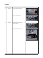
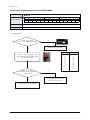
ఐ Essential Requirements before PCB Changes in Case of Communication Error Occurrence
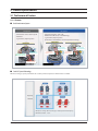
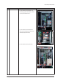
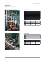
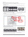
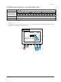
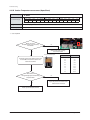
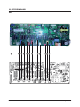
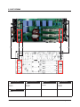
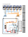
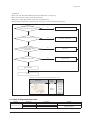
1. Find the communication IC near the communication terminal.
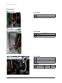
Ɣ Indoor Unit
- Above Red Connector : Communication IC between indoor and outdoor units.
- Above Blue Connector : Communication IC for cable remote control.
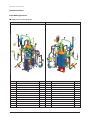
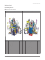
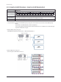
Ɣ Outdoor Unit
- When there is module communication as in PLUS II and PLUS III –
Above Red Connector of Main Unit : Communication IC between indoor and outdoor units.
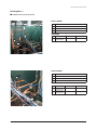
- When there is no module communication as in PLUS II and PLUS III –
Above Yellow Connector of Each Unit : Communication IC between outdoor units.
- Other Outdoor Unit- Above Communication Connector : Communication IC between indoor and outdoor unit.
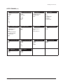
Indoor Unit communication
Transmitter communication
Indoor Unit
Outdoor unit
communication between
Outdoor Unit
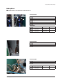
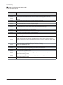
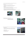
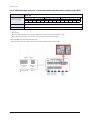
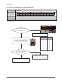
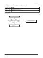
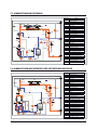
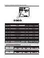
2. Measure the resistance of the communication IC.
Ɣ Measurement Method : Measure the No.5 - No.6 Pin resistance
Measure the No.5 - No.7 Pin resistance
Measure the No.5 - No.8 Pin resistance
Display IC No. 1 pin
No.5
No.6
No.7
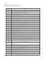
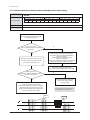
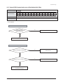
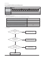
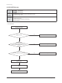
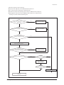
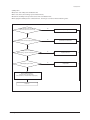
3. Normal and defective judgment is tested for communication IC by using measured resistance.
Ɣ Judging as Normal
- Each resistance value should be measured in tens of kΩ~to hundreds of kΩ.
- Difference between the two resistance values should be of some number of kΩ.
Ɣ Judging as defective
- One or both are low with tens of Ω
- One or both of them is open
Samsung Electronics
4-17