1
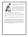
1926 Hudson-Essex Service Manual
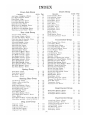
INDEX
Hudson Service & Repairs
Essex Service & Repairs
Reference Sheets:
Hudson & Essex Alloy Pistons
“
“ “ Chain Front End Drive
“
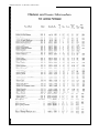
“ “ Information for License Purposes
Windshield, Top & Body Glass Specifications
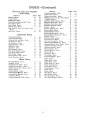
Hudson & Essex Coach Repairs:
Door Regulator Repairs
Replace Door Glass
To Eliminate Squeeks at Top Corners
To Fit Channel to Window Glass
To Replace Quarter Glass
Minor Body Repairs
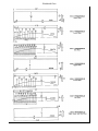
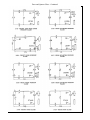
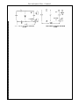
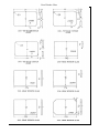
Wiring Diagrams
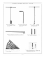
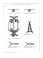
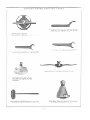
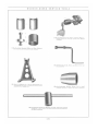
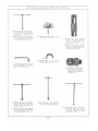
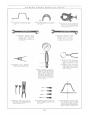
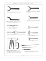
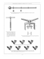
Hudson & Essex Service Tools
3
93
174
178
182
186
199
201
203
205
207
209
219
222
HUDSON
SERVICE - REPAIRS
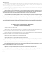
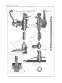
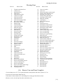
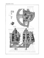
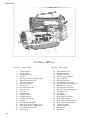
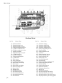
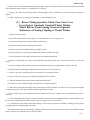
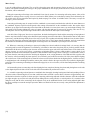
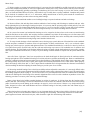
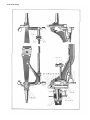
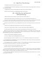
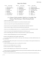
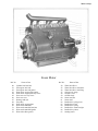
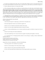
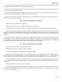
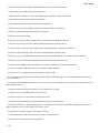
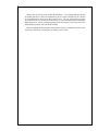
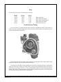
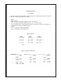
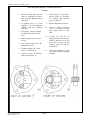
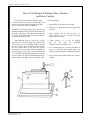
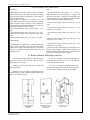
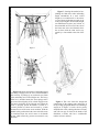
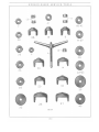
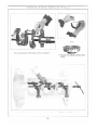
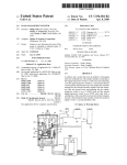
Front Axle Group
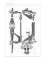
Hudson Front Axle
Ref. No.
1.
2.
3.
4.
5.
6.
7.
8.
9.
10.
11.
12.
13.
14.
15.
16.
17.
18.
19.
20.
Name of Part
Front wheel outer bearing
Spindle washer
Spindle nut
Spindle-left hand
Front wheel inner bearing
Front wheel dust washer retainer-outer
Front wheel dust washer
Front wheel dust washer retainer-inner
Spindle shim
Spindle pivot pin lower bushing
Lower bushing pipe plug
Tie rod pivot pin lock
Spindle pivot pin oiler
Steering arm nut
Pivot pin oiler elbow
Pivot pin dust shield
Pivot pin dust washer
Spindle pivot pin upper bushing
Spindle pivot pin
Thrust bearing shield
Ref. No.
Name of Part
21. Thrust bearing
22. Spindle pivot pin lock
23. Tie rod pivot pin lower bushing
24. Tie rod pivot pin washer
25. Tie rod pivot pin nut
26. Tie rod pivot pin shield
27. Tie rod pivot pin upper bushing
28. Tie rod pivot pin
29. Steering arm ball
30. Steering arm-left hand
31. Steering arm ball nut
32. Axle center
33. Tie rod yoke clamp bolt nut
34. Tie rod yoke
35. Tie rod
36. Tie rod clamp bolt
37. Spindle-right hand
38. Steering arm stop screw
39. Steering arm stop screw nut
40. Steering arm-right hand
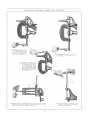
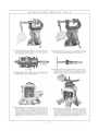
(A) Renew Spindle Pivot Pin Bushings and Pins
1. Jack up or block up front end of car.
2. Remove front hub caps and spindle nuts (3); take off wheels.
3. Remove drag link front end boot, cotter pin and front end adjusting plug, then disconnect drag link from steering arm ball
(29).
4. Remove cotter pins, nuts (25) and washers from bottom of tie rod pivot pins (28).
5. Drive out flat side lock pins (12) from steering arms, remove tie rod pivot pins and tie rod assembly.
6. Remove oil cup elbows (15), dust caps (16), and dust washers (17) from top of spindle pivot pins and pipe plugs (11) from
lower bushings.
7. Drive out flat side lock pins (22) from spindles and drive out spindle pivot pins (19) with drift inserted through pipe plug
holes in lower bushings, allowing spindles (4), thrust bearings (21), and shims (9) to be removed. Note: If spindle pivot pins are
rusted or frozen in spindle, it will be necessary to force them out with the spindle pivot pin remover shown on page 32, service
tool section.
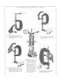
8. Remove old bushings (10, 18) and insert new ones, using pivot pin bushing press shown on page 3, service tool section,
which will prevent damage to the parts and insure proper alignment of the bushings so that the pivot pins will operate freely.
9. To reassemble, reverse above operations, making sure that pivot pins turn freely, without shake, and that the proper number
of shims are inserted between bottom of spindle and top of lower bushing to eliminate up and down play.
(B) Renew Tie Rod Pivot Pin Bushings and Pins
1. Remove cotter pins, nuts (25) and washers from bottom of tie rod pivot pins (28).
2. Drive out tie rod pivot pin locks (12) from steering arms; take out pivot pins (2 8) and remove, tie rod assembly.
[3]
Front Axle Group
3. Remove old bushings (23, 27) from tie rod yokes and press in new ones, using bushing press shown on page 12, service
tool section.
4. Reassemble parts to axle, by reversing the above operations.
(C) Straighten* or Replace Front Axle Center
*This procedure we do not recommend unless the axle center is only slightly bent and the proper equipment available to
straighten it cold. Heating the axle to straighten it should be avoided, as this destroys the original heat treatment, with the result
that the part is weakened and a satisfactory or lasting job is seldom obtained.
1. Raise front end of car with chain hoist or by jacks or blocking under frame side members, directly back of front springs.
2. Remove front hub caps, cotter pins and spindle nuts (3); take off front wheels.
3. Remove drag link front end boot, cotter pin and front end adjusting plug, then disconnect drag link from steering arm ball
(29)..
4. Remove cotter pins, nuts (25) and washers from bottom of tie rod pivot pins (28).
5. Drive out tie rod pivot pin locks (12); take out pivot pins and tie rod assembly.
6. Remove oil cup elbows (15), dust caps (16), and dust washers (17), from top of spindle pivot pins, also pipe plugs (11)
from bottom of lower bushings.
7. Drive out flat sided lock pins (22) from spindles and drive out spindle pivot pins (19) with drift inserted through pipe plug
holes in lower bushings, allowing spindles, thrust bearings (21) and shims (9) to be removed. If the spindle pivot pin is rusted
or frozen in the spindle, it should be removed with the spindle pivot pin remover shown on page 32, service tool section.
8. Remove front spring clip nuts, clips and rubber bumpers. This will release the front axle center (32), which may be
removed and straightened or replaced with a new part. (See note above.) If the axle center is straightened, care must be exercised
to have the pivot pins parallel to each other in all directions and perpendicular to the spring seats. It is very important that these
points be observed, as they materially affect the steering of the car and tire wear.
9. To reassemble axle, reverse the above operations.
(D) Renew Front Wheel Bearings,
Washers, or Retainers
1. Remove front hub caps, cotter pins and spindle nuts (3); take off front wheels.
2. Remove inner bearing cone and rolls from spindle, using bearing cone and roll puller shown on page 26 service tool
section, if necessary; this will allow the removal of the felt washer retainers (6) and felt washers (7).
3. The bearing cups are best removed from the wheel hubs by the use of the bearing outer cup puller shown on page 14,
service tool section, inserting the lugs of the puller through the openings in the inside flanges of the hubs, against which the cups
seat. They may, however, be removed by inserting a drift through these openings and tapping on opposite sides lightly with a
hammer. The new bearing cups should be fitted into position with the puller or by means of a soft hammer.
4. The parts may be reassembled by reversing the above operations, using care to make sure that the bearings are properly
adjusted as outlined in Article "E."
[4]
Front Axle Group
(E) Adjust Front Wheel Bearings
1. Jack up car under front axle.
2. Remove front hub caps, and spindle nut cotter pins.
3. Adjust spindle nuts (3), so that when the wheel is grasped at the top and bottom, all perceptible play or looseness will be
taken up. If the wheels do not turn freely after the cotter pins have been replaced, the spindle nuts should be backed off and the
cotter pins inserted in the next notch, otherwise destruction of the bearings may result.
4. Add grease if necessary, and replace hub caps.
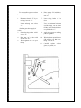
(F) Align Front Wheels
One of the most important factors governing the life of the front tires and ease of steering, is the alignment of the front
wheels. In view of this, it is advisable to check the alignment of the wheels after front axle repairs have been made, or whenever
there is a possibility of the parts having been damaged by skidding or accident.
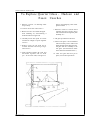
The operation of checking wheel alignment is greatly simplified and the time reduced by the use of a wheel aligning gauge,
similar to that shown in the equipment section. This instrument is used by telescoping it and inserting it between the tires, ahead
of the front axle, so that the ends of the chains just touch the floor. The pointer should then be set to zero, and the car moved
forward until the gauge is to the rear of the front axle, with the ends of the chains just touching the floor. The difference between
the measurements taken between the inside of the tires ahead of and behind the axle, or the amount of toe-in, will then be
immediately apparent by merely reading the scale on the gauge.
The distance between the inside of the tires at the rear, should be the same as the distance at the front, or range between that
and 1/8” greater than the measurement at the front. If the toe-in or variation exceeds this amount or if the distance between the
tires at the front is greater than the distance at the rear, the tie rod should be adjusted as follows:
1. Remove cotter pin, nut (25) and washer from tie rod pivot pin (28).
2. Drive out pivot pin lock (12), remove pivot pin and disconnect tie rod.
3. Loosen tie rod yoke clamp bolt (36), turn yoke (34) one complete turn to right if toe-in is too great, or to left if
insufficient; drop tie rod pivot pin in place and check alignment. Repeated trials should be made if necessary, until the proper
adjustment is obtained.
4. Replace tie rod, pivot pin, lock, washer, nut and cotter pin; tighten clamp bolt securely.
[5]
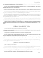
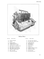
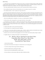
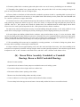
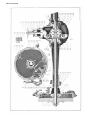
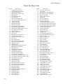
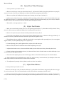
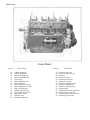
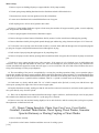
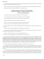
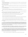
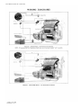
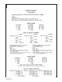
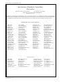
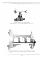
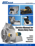
Rear Axle Group
Hudson Rear Axle
Ref. No. Name of Part
Ref. No. Name of Part
1. Rear wheel bearing adjusting nut lock
2. Adjusting nut clamp bolt nut
3. Adjusting nut clamp bolt
4. Tension rod adjusting nut
5. External brake band upper bracket
6. Tension rod washer
7. Tension rod spring
8. Internal brake lining
9. Internal brake band
10. Internal brake band end bracket
11. Internal brake anchor bracket
12. Internal brake link
13. Tension rod nut
14. Internal brake spring clip
15. Tension rod
16. External brake bracket
17. Internal brake shaft bracket
18. External brake operating lever
19. Internal brake link clevis pin
20. Tension rod clevis pin
21. Internal brake main spring
22. External brake band lower bracket
23. Internal brake tie bar
24. External brake band
25. Internal brake adjusting link nut
26. Internal brake adjusting link
27. Internal brake adjusting link clevis pin
28. Internal brake band bracket clevis pin
29. Internal brake stop bracket
30. Internal brake shaft
31. Axle shaft nut
32. Rear wheel hub
33. Axle shaft key
34. Internal brake shaft bracket bushing
35. Internal brake operating lever
36. Operating lever clamp bolt nut
37. Wheel bearing adjusting nut felt washer
38. Internal brake operating lever clamp bolt
39. Rear wheel bearing adjusting nut
40. Axle drive shaft felt washer
41. Rear wheel bearing
42. Axle shaft felt washer
43. Pinion shaft bearing cage lock
44. Pinion shaft bearing cage clamp bolt
45. Oil filler elbow
46. Pinion shaft rear bearing
47. Oil filler elbow plug
48. Drive gear inspection plug
49. Drive pinion
50. Axle housing inner felt washer-small
51. Axle housing inner felt washer-large
52. Axle housing inner felt washer retainer
53. Axle shaft
54. Rear wheel bearing oiler
55. External brake anchor bracket
56. Differential bearing adjusting nut
57.
58.
59.
60.
61.
62.
63.
64.
65.
66.
67.
68.
69.
70.
71.
72.
73.
74.
75.
76.
77.
78.
79.
80.
81.
82.
83.
84.
85.
86.
87.
88.
89.
90.
91.
92.
93.
94.
95.
96.
97.
98.
99.
100.
101.
102.
103.
104.
105.
106.
107.
108.
109.
110.
111.
Differential bearing
Differential bearing nut lock
Adjusting nut lock clevis pin
Differential gear
Drive gear bolt
Differential pinion
Differential case left hand
Drive gear bolt nut lock
Drive gear
External brake band spacer bar
Spacer stud
Spacer stud spring
Spacer stud washer
Spacer stud bracket
Spacer stud nut
Lining rivet
External brake lining
Internal brake spacer clip
Internal brake spacer bracket
Internal brake spacer spring
Internal brake spacer screw nut
Internal brake spacer screw
External brake anchor bracket spring
External brake band bracket-center
External brake anchor bracket screw
Anchor bracket screw lock
Pinion shaft felt washer retainer-front
Pinion shaft felt washer retainer-rear
Pinion shaft nut
Universal joint flange
Pinion shaft key
Pinion shaft adjusting sleeve lock nut
Pinion shaft adjusting sleeve nut lock
Pinion shaft adjusting sleeve
Pinion shaft dust collar
Pinion shaft felt washer
Pinion bearing cage
Pinion shaft front bearing
Pinion bearing oiler
Differential carrier
Axle shaft thrust plug
Differential carrier bolt
Differential carrier gasket
Rear axle housing
Housing cover gasket
Differential carrier cap
Housing cover screw
Differential carrier cap bolt
Differential case right hand
Differential case screw
Differential case screw lock
Differential spider
Drive gear bolt nut
Housing cover plug
Housing cover
[9]
Rear Axle Group
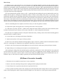
(A) Repair or Renew Axle Housing
1. Jack up or block up car under rear springs ahead of rear axle, or raise rear end of car with chain hoist until car weight is off
the rear springs.
2. Place receptacle under housing to catch lubricant, remove housing cover cap screws (103) and housing cover.
3. Remove rear hub caps, cotter pins and axle shaft nuts (31), pull rear wheels off axle shafts, using wheel puller shown on
page 22, service tool section. Note: Be sure hand brakes are fully released before attempting to pull off wheels.
4. Remove clamp bolts (3) and bearing adjusting nut locks (1), unscrew bearing adjusting nuts (39), using bearing adjusting
nut wrench shown on page 6, service tool section, pull out axle shafts and wheel bearings.
5. Remove clevis pins from internal and external brake operating levers (35, 18) and disconnect brake pull rods.
6. Remove flange bolts at rear universal joint and disconnect propeller shaft.
7. Place blocking or jacks under axle housing; takeoff rear spring clip nuts and plates, which will allow the lowering and
removal of the axle from under car.
8. The axle may now be placed on a bench or axle stand, and the differential carrier and gear set assembly removed by
taking off the cap screws (98), which secure it to the housing.
9. Remove external brake anchor bracket adjusting screw locks (82), adjusting screws (81) and springs (79).
10. Remove tension rod adjusting nuts (4), springs (7), and clevis pins (20).
11. Remove spacer stud nuts (71) and springs (68); this will permit the removal of the external brake bands.
12. Remove clamp bolts (38), take off internal brake operating levers (35).
13. Remove spacer bracket screws (78), springs (76), main springs (21) and adjusting link clevis pins (27); this will allow
the removal of the internal brake bands and operating shafts (34).
14. Any necessary welding or riveting operations may, now be performed or new housing assembly installed and the axle
reassembled, reversing the above operations, and making sure that the wheel bearings are properly adjusted as outlined in
Article "N."
(B) Renew Carrier and Gear Set Assembly
1. Jack up or block up rear end of car.
2. Remove rear hub caps, cotter pins and axle shaft nuts (31), pull wheels off axle shafts, using wheel puller shown on page
22, service tool section. Note: Be sure hand brakes are fully released before attempting to pull off wheels.
3. Remove clamp bolts (3), bearing adjusting nut locks (1) and unscrew adjusting nuts (39), using bearing adjusting nut
wrench shown on page 6, service tool section; pull out axle shafts and bearings.
4. Place receptacle under axle housing to catch lubricant, and remove lower carrier to housing cap screw (98).
5. Remove flange bolts at rear universal joint and disconnect propeller shaft.
6. Take off remaining screws holding carrier to axle housing and remove carrier and gear set assembly.
7. Install new carrier and gear set assembly and reassemble axle, reversing the above operations, and making sure that the
wheel bearings are properly adjusted as detailed in Article "N."
[10]
Rear Axle Group
(C) Renew Axle Drive Shaft
1. Jack up or block up car under rear axle.
2. Remove rear hubcap, cotter pin and axle shaft nut (31); pull wheel off axle shaft, using wheel puller shown on page 22,
service tool section. Note: Be sure hand brakes are fully released before attempting to pull off wheels.
3. Remove clamp bolts (3), bearing adjusting nut locks (1), and unscrew bearing adjusting nuts (39), using bearing adjusting
nut wrench shown on page 6, service tool section; pull out axle shafts and wheel bearings. Note: It is occasionally necessary, in
the case of a broken axle shaft, to remove the shaft on the opposite side as well, so that a rod may be inserted to push out the
inner part of the broken shaft.
4. Press bearing cone and rolls off axle shaft and install on new shaft, using arbor press, or bearing cone and roll puller shown
on page 6, service tool section. If these are not available, this may be done by holding the shaft in a vertical position with the
tapered end downward, and tapping upper side of cone with hammer and brass rod.
5. Install new shaft and reassemble axle, reversing above operations.
(D) Renew Differential Carrier
1. Jack up or block up car under rear axle.
2. Remove rear hub caps, cotter pins and axle shaft nuts (31); pull rear wheels off axle shafts, using puller shown on page
22, service tool section. Note: Be sure hand brakes are fully released before attempting to pull off wheels.
3. Remove clamp bolts (3) and bearing adjusting nut locks (1), unscrew bearing adjusting nuts (39), using bearing adjusting
nut wrench shown on page 6, service tool section; pull out axle shafts and bearings.
4. Remove lower carrier to housing cap screw (98) and drain lubricant.
5. Remove flange bolts at rear universal joint and disconnect propeller shaft.
6. Take off remaining screws holding carrier to axle housing, remove carrier and gear set assembly and place on bench or
stand.
7. Remove carrier cap bolts (104), and caps (102); take out differential and drive gear assembly.
8. Remove pinion bearing cage clamp bolt (44) and lock (43) from front of carrier, unscrew drive pinion cage (93), using
spanner wrench shown on page 22, service tool section.
9. Fit new carrier and reassemble axle by reversing the above operations. Make sure that the pinion shaft, differential and
wheel bearings, also drive gear and pinion are properly adjusted and lubricant added, as covered in Articles "L," "M" and "N."
(E) Renew Wheel Bearing
1. Jack up or block up car under rear axle.
2. Remove rear hub cap, cotter pin and axle shaft nut (31); pull rear wheel off axle shaft, using wheel puller shown on page
22, service tool section. Note: Be sure hand brakes are fully released before attempting to pull off wheel.
3. Remove clamp bolt (3) and bearing adjusting nut lock (1), unscrew bearing adjusting nut (39), using bearing adjusting
nut wrench shown on page 6, service tool section; pull out axle shaft and bearing.
[11]
Rear Axle Group
4. Press bearing cone and rolls off axle shaft, using arbor press or bearing cone and rod puller shown on page 6, service
tool section. If these are not available, this may be done by holding the shaft in a vertical position with the tapered end
downward, and tapping upper side of cone with hammer and brass rod.
5. Fit new bearing cone to axle shaft taper, first making sure that cone and shaft are clean and free from burrs which might
prevent the bearing from seating properly.
6. Remove bearing outer cup from adjusting nut, by screwing adjusting nut back into axle housing, and tapping cup loose
by means of a punch or short piece of 7/32” rod, inserted through opposite holes drilled near edge of nut. When doing this,
care should be taken to tap the bearing cup alternately through each hole, to insure its coming out straight.
7. Clean thoroughly inside of adjusting nut and new outer cup. The pressing in place of the cup is best done in an arbor
press; however, if care is used a satisfactory job can be done with the aid of a large vise or soft hammer. In performing this
operation, it is very essential that the inner side of the cup, when pressed in place, is parallel with the inside of the adjusting
nut; otherwise, the binding which will take place when assembled in the axle may cause the destruction of the bearing.
8. The parts may now be reassembled by reversing operations 1, 2, and 3. The rear wheel bearings should be adjusted to
allow an end play in the axle shafts of approximately .005" to .010”. In addition, it is necessary that the adjusting nuts be
screwed into the axle the same distance on each side to guard against interference between the brake drums and support brackets.
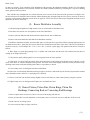
(F) Renew Drive Gear and Pinion, Differential
Bearings or Pinion Shaft Bearings
1. Jack up or block up car under rear axle.
2. Remove hub caps, cotter pins and axle shaft nuts (3 1), pull wheels off axle shafts, using wheel puller shown on page
22, service tool section. Note-Be sure hand brakes are fully released before attempting to pull off wheels.
3. Remove clamp bolts (3) and bearing adjusting nut lock (1), unscrew bearing adjusting nuts (39), using bearing adjusting
nut wrench shown on page 6, service tool section; pull out axle shafts and bearings.
4. Remove lower carrier to housing cap screw (98) and drain lubricant.
5. Remove flange bolts at rear universal joint and disconnect propeller shaft.
6. Take off remaining screws holding carrier to axle housing; remove carrier and gear set assembly and place on bench or
stand.
7. Take off cap bolts (104) and caps (102); remove differential and drive gear assembly.
8. If new differential bearings are to be fitted, remove cone and rolls from differential case hubs and install new ones, using
bearing cone and roll puller shown on page 5, service tool section.
9. Bend over ears on drive gear bolt nut locks (64), remove nuts (109) and bolts (61); take off drive gear.
10. Thoroughly clean differential case flange, also flange of new drive gear of chips and foreign matter; place gear in
position and insert bolts. Fit new nut locks if necessary, draw up bolts securely and bend over nut lock ears.
[12]
Rear Axle Group
11. Remove pinion bearing cage clamp bolt (44) and lock (43) from front end of carrier and unscrew pinion bearing cage
(93), using spanner wrench shown on page 22, service tool section.
12. Remove cotter pin and nut (85) from front end of pinion shaft and pull off universal joint flange (86), using universal
joint flange puller shown on page 6, service tool section.
13. Bend over lugs on pinion shaft nut lock (89), remove lock nut (88), nut lock (89), adjusting nut (90), drive pinion and
bearings.
14. Remove bearing cone and rolls from pinion shaft, using puller shown on page 5, service tool section, and press onto new
drive pinion, or fit new bearing cone and rolls on old pinion if bearings are to be renewed.
15. Remove old bearing outer cups from pinion cage (93) using bearing race puller shown on page 5, service tool section, or
by holding cage in upright position, and driving out cups by means of a long drift or piece of steel, inserted through opposite
slots in inside flanges against which bearing cups seat.
16. Clean thoroughly inside of bearing cage and new outer cups. An arbor press or bearing race puller should be used when
pressing the new cups into position; however, a soft hammer may be used to drive them in place, provided care is taken to start
them straight, and tap evenly all around the edges of the cups.
17. The axle may now be reassembled by reversing operations 1 to 13, making sure that parts are properly lubricated and the
pinion shaft, differential and wheel bearings, also drive gear and pinion, are properly adjusted as outlined in Articles "L," "M"
and “N”.
(G) Renew Pinion Shaft Felt Washer
1. Remove flange bolts at rear universal joint and disconnect propeller shaft.
2. Remove cotter pin and nut (85) from pinion shaft and pull off universal joint flange (86) using universal joint flange puller
shown on page 6, service tool section.
3. Straighten lugs on pinion shaft nut lock (89) remove lock nut (88) and adjusting nut (90)
4. Remove felt washer retainer (83) using felt washer retainer puller. If no puller is available, insert hooked tool or offset
screwdriver behind retainer, removing same by prying evenly around inside edge.
5. Remove felt washer (92) and replace with new part; straighten or replace retainer if damaged in removing, and tap in
position.
6. To reassemble parts, reverse operations 1, 2 and 3, making sure that the drive gear and pinion, also pinion shaft bearings,
are properly adjusted as outlined in Articles "L" and "M."
(H) Renew Axle Shaft Felt Washers
1. Jack up or block up car under rear axle.
2. Remove rear hub caps, cotter pins and axle shaft nuts (31), pull wheels off axle shafts, using wheel puller shown on page
22, service tool section. Note: Be sure hand brakes are fully released before attempting to pull off wheels.
3. Remove clamp bolts (3) and bearing adjusting nut locks (1), unscrew bearing adjusting nuts (39), using bearing adjusting
nut wrench shown on page 6, service tool section; pull out axle shafts and bearings.
4. Remove felt washer (42, 37) from axle and bearing adjusting nuts and replace with new parts.
[13]
Rear Axle Group
5. To reassemble parts to axle, reverse the above operations, making sure that the wheel bearings are properly adjusted as
outlined in Article "N."
(I) Renew Differential Case Gears, Pinions or Spider
1. Jack up or block up car under rear axle.
2. Remove rear hub caps, cotter pins and axle shaft nuts (31), pull wheels off axle shafts, using wheel puller shown on page
22, service tool section. Note: Be sure hand brakes are fully released before attempting to pull off wheels.
3. Remove clamp bolts (3) and bearing adjusting nut locks (1); unscrew bearing adjusting nuts (39), pull out axle shafts and
wheel bearings.
4. Place receptacle under housing to catch lubricant, remove housing cover screws (103) and take off cover.
5. Remove carrier cap bolts (104), caps (102) and adjusting nuts (56); take out differential and drive gear assembly.
6. Place differential assembly on bench; bend back lugs on bolt locks (107), remove screws (106) and take apart case.
7. Replace case or any other differential parts which require renewal.
8. To reassemble parts to axle, reverse the above operations, using care to see that the drive gear and pinion, differential
bearings and wheel bearings are properly adjusted as outlined in Articles "M" and "N."
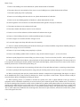
(J) Reline Internal Brakes
1. Jack up or block up car under rear axle.
2. Remove rear hub caps, cotter pins and axle shaft nuts (31); pull wheels off axle shafts, using wheel puller shown on page
22, service tool section. Note: Be sure hand brakes are fully released before attempting to pull off wheels.
3. Remove clevis pins from external brake operating levers (18) and disconnect brake pull rods.
4. Remove clevis pins (20) and adjusting nuts (4) from tension rods; take off tension rods (15) and springs (7).
5. Remove lock wires (82), adjusting screws (81) and springs (79) from anchor brackets.
6. Remove nuts (71) and springs (68) from spacer studs (67); this will release external brake bands, which may now be
removed.
7. Remove internal brake main springs (21).
8. Remove clevis pins (27) from adjustable links (26).
9. Remove internal brake spacer clip adjusting screws (78) and springs (76); take off internal brake bands.
10. Drive out lining rivets and remove old lining; fit new lining, making sure that it conforms to the curvature of the brake
bands and that the rivet holes are countersunk sufficiently to allow the rivet heads to set well beneath the surface.
11. To reassemble parts to axle, reverse the above operations. Make sure that the brakes are properly adjusted as detailed in
Articles "O" and "P."
[14]
Rear Axle Group
(K) Reline External Brakes
1. Jack up or block up car under rear axle.
2. Remove rear hub caps, cotter pins and axle shaft nuts (31); pull wheels off axle shafts, using wheel puller shown on page
22, service tool section. Note: Be sure hand brakes are fully released before attempting to pull off wheels.
3. Remove clevis pins from external brake operating levers (18) and disconnect pull rods.
4. Remove clevis pins (20) and adjusting nuts (4) from tension rods, take off tension rods (15) and springs (7).
5. Remove lock wires (82), adjusting screws (81) and springs (79) from anchor brackets.
6. Remove nuts (71) and springs (68) from spacer studs (67); this will release external brake bands, which now may be
removed.
7. Drive out lining rivets and remove old lining; fit new lining, making sure that it conforms to the curvature of the brake
bands, and that the rivet holes are countersunk sufficiently to allow the rivet heads to set well beneath the surface.
8. To reassemble parts to axle, reverse the above operations. Make sure that the brakes are Proverlv adiusted as outlined in
Articles "O" and "P."
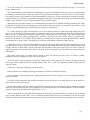
(L) Adjust Drive Pinion Bearings
1. Straighten lugs on nut lock (89) and loosen lock nut (88).
2. Turn adjusting nut (90) until all perceptible play or looseness in the bearings is taken up, using care to see that they are
not adjusted too tightly.
3. Tighten lock nut (88), then test bearing adjusting to make sure it has not been disturbed.
4. Bend over lugs on nut lock (89), locking adjusting and lock nuts in position.
(M) Adjust Drive Gear and Pinion and
Differential Bearings
1. Make sure drive pinion bearings are properly adjusted as outlined in Article
2. Remove inspection plug (48) in side of carrier and examine position of drive gear and pinion.
3. Remove clamp bolt (44) and pinion bearing cage lock (43), from front of carrier.
4. Engage spanner wrench shown on page 22, service tool section, with slots in flange of pinion bearing cage (93); turn
cage in housing until back face of drive pinion teeth is flush with outside face of drive gear teeth.
When in this position, the backlash or play between the drive gear and pinion teeth should be approximately .006” to .008”.
If the backlash is greater or less than this amount, it will be necessary to adjust the differential and drive gear, which is
accomplished as follows:
5. Place receptacle under housing to catch lubricant, remove housing cover cap screws (103) and cover.
6. Disengage adjusting nut locks (58) from slots in adjusting nuts, and loosen cap bolts (104) very slightly.
[15]
Rear Axle Group
7. Back off adjusting nut (56) (R. H. if backlash is excessive, L. H. if insufficient) by turning to left or anti-clockwise.
8. Turn adjusting nut (L. H. if backlash is excessive, R. H. if insufficient) to right or clockwise, until required amount of
play is present between drive gear and pinion teeth.
9. Turn adjusting nut (R. H. if backlash is excessive, L. H. if insufficient) to right or clockwise, until all perceptible looseness in differential bearings is taken up, using care to see that they are not adjusted too tightly.
10. Tighten cap bolts and wire heads, place nut locks in position; then inspect gear and bearing adjustments to see that they
have not been disturbed.
11. Replace pinion bearing cage lock and clamp bolt at front of carrier.
12. Replace inspection plug in side of carrier.
13. Replace housing cover and fill housing with lubricant to level of pipe plug opening in cover.
14. The car should now be driven and results noted. If the axle is still noisy, it will be necessary to remove clamp bolt (44)
and pinion bearing cage locks (43). Turn pinion bearing cage until next notch is in position, by means of spanner wrench, then
replace lock and bolt. Repeated trials should be made if necessary, moving the bearing cage adjustment a notch at a time in
either direction, until satisfactory results are obtained.
(N) Adjust Rear Wheel Bearings
1. Jack up or block up car under rear axle.
2. Remove rear hub caps, cotter pins and axle shaft nuts (31); pull wheels off axle shafts, using wheel puller shown on page
22, service tool section. Note: Be sure hand brakes are fully released before attempting to pull off wheels.
3. Remove clamp bolts (3) and bearing adjusting nut locks (1).
4. Adjust wheel bearings, turning adjusting nuts (39) to right or clockwise to tighten or to left or anti-clockwise to loosen,
using wheel bearing adjusting nut wrench shown on page 22, service tool section. In making this adjustment it is important
that an end play of from .005” to .010” remain in the axle shafts and that the adjusting nuts be screwed into the housing approximately the same distance on each side, to prevent interference between the brake drums and support brackets.
5. Reassemble, reversing operations 1, 2 and 3.
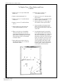
(O) Adjust Foot Brakes
1. Make sure external brake operating levers (18) rest against support brackets (16) when brakes are fully released.
With the operating levers in this position, the cross shaft levers should point to the ear at an angle of about 30º from the vertical. If they do not, it will be necessary to adjust as follows:
2. Disconnect cross shaft to rear axle pull rods by removing clevis pins from yokes at rear end.
3. Adjust stop screw at lower part of brake pedal so there will be approximately 1/4” clearance between pedal and toe board
in fully released position.
4. Lengthen or shorten rod connecting brake pedal to equalizer bar, by loosening lock nuts and turning adjusting turnbuckle
to right or left until cross shaft levers are in the position indicated in operation 1.
[16]
Rear Axle Group
5. Lengthen or shorten rods connecting cross shaft to rear axle brake operating levers, by turning adjusting yokes to right
or left until rods are correct length; then tighten lock nuts and replace clevis and cotter pins.
6. Remove lock wires (82) from anchor bracket screw heads.
7. Adjust anchor bracket screws (81) so that external brake bands just clear the brake drums at these points and replace lock
wires.
8. Loosen lock nuts and turn tension rod nuts (13) down until lower halves of brake bands are raised sufficiently to just clear
brake drums, then tighten lock nuts.
9. Turn tension rod adjusting nuts (4) down until the upper halves of the brake bands also just clear the brake drums.
10. Inspect adjustment of external brake spacer studs (67), and if necessary, loosen lock nuts (71) and adjust, so that with
brakes fully released, the brake bands will be raised clear of the drums.
11. Test adjustments, by turning wheels by hand to make sure there is no tendency for the brakes to drag.
(P)
Adjust Hand Brakes
1. Jack up or block up car under rear axle.
2. Remove rear hub caps, cotter pins and axle shaft nuts (3 1), pull wheels off axle shafts, using wheel puller shown on page
22, service tool section. Note: Be sure hand brakes are fully released before attempting to pull off wheels.
3. Make sure internal brake tie bars (23), rest against stop brackets (29), when the hand brake lever is fully released. With
the tie bars and hand brake lever in this position, the internal brake cross shaft levers should point to the rear, at an angle of
about 30º from the vertical. If they do not, it will be necessary to adjust, as follows:
4. Loosen lock nuts on pull rod connecting cross shaft to hand brake lever, turn turnbuckle to right or left as necessary until
cross shaft levers are at proper angle, then tighten lock nuts.
5. Lengthen or shorten pull rods connecting cross shaft levers with rear axle internal brake shaft levers, by turning adjusting
yokes to right or left until brake tie bars are in the position indicated in operation No. 3.
6. Place in position on axle shaft, brake band aligning fixture shown on page 22, service tool section.
7. Loosen spacer clip adjusting screw nuts (77) and turn adjusting screws (78) until brake bands just clear the drums at these
points, then tighten nuts.
8. Remove clevis pins (27) from adjusting links (26).
9. Loosen link nuts (25) and expand brake bands until they just clear the brake drums, by turning adjusting links (26) to left
or anti-clockwise.
10. Tighten lock nuts, replace clevis and cotter pins, then remove aligning fixture after turning same by hand to make sure
the brake bands do not drag.
11. Place rear wheels in position, but do not draw them up tight on axle shaft taper. Pull up hand brake lever a notch at a time,
grasping the rear wheels, and noting whether or not the braking effort is equal on both sides. If one wheel offers less resistance
to turning than the other, it should be taken off and the brake bands expanded further, as outlined in operations 8, 9 and 10.
12. After the brakes have been properly adjusted and equalized, the parts may be reassembled by reversing operations No. 1
and 2.
[17]
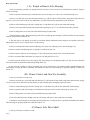
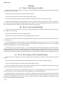
Spring Assembly Group
Springs
(A) Renew Front Spring Assembly
1. Raise front end of car with chain hoist or by jacks or blocking under frame side members directly back of front springs,
until weight of car is off springs.
2. Remove nuts from front spring clips and take off clips.
3. Remove cotter pins and nuts from front end and shackle bolts, take out bolts and shims; this will allow the removal of the
front spring assembly.
4. Install new spring assembly, reversing operations 1, 2 and 3, making sure that the spring clip nuts are securely tightened.
It is essential, when reassembling front end and shackle bolts, to draw the nuts up tight and then back them off 1/6th of a turn
before inserting cotter pins to take up side play and insure freedom of spring action.
(B) Renew Front Spring Bushings
1. Raise up front end of car with hoist or by jacks or blocking under frame side members, directly back of front springs so
that weight of car is off springs.
2. Remove nuts from bottom of clips holding spring to front axle and take off front spring clips.
3. Remove cotter pins and nuts from front end and shackle bolts, take out bolts and front end shims; this will allow the
removal of the spring assembly.
4. Press out old bushings and insert new ones, using spring bushing remover shown on page 12, service tool section. If
necessary, use 11/16” expansion reamer to bring bushings to size after pressing in place. When pressing rear bushings in
position, be sure oil holes in bushings line up with holes in spring leaves.
5. Install springs on car, reversing operations 1, 2, and 3, making sure that spring clip nuts are securely tightened. When
tightening front spring front end bolts, it is essential that the nuts be drawn up tight and then backed off 1/6th of a turn before
inserting cotter pin, so that side play will be eliminated without interfering with the spring action. The rear end or shackle bolts
should be backed off 1/6th of a turn after tightly screwing them into shackles; then tighten lock nut securely.
(C) Renew Rear Springs or Rear Spring Bushings
1. Raise rear end of car with hoist, or by jacks or blocking under frame ahead of rear springs, so that weight of car is just
off springs.
2. Remove nuts and lock nuts from bottom of clips holding spring to rear axle and take off spring clip plate.
3. Remove cotter pin and nut from rear spring front end bolt, take out bolt and shims.
4. Remove nut and lock washer from rear end or shackle bolt and unscrew bolt out of shackle; this will allow the removal
of the rear spring, which may be renewed or rebushed as necessary.
5. If spring is to be rebushed, press out old bushings and insert new ones, using spring bushing remover shown on page 12,
service tool section. If necessary to bring bushings to size after pressing them in place, use 3/4” expansion reamer on front end
bushing and 11/16” reamer on rear end bushing.
6. Install spring on car, reversing operations 1 to 4 inclusive, making sure that rear spring clip nuts and lock nuts are drawn
up tightly. When assembling front end bolt,
[18]
Spring Assembly Group
care must be taken to back off the nut 1/6th of a turn after tightening, before inserting cotter pin, to insure free spring action. In
like manner, the rear or shackle bolt should be backed off slightly after being tightly screwed into the shackle and before
tightening lock nut.
(D) Remove Side Play from Front or Rear Springs
1. Remove cotter pins from ends of front and rear spring front end bolts.
2. Draw up front and rear spring front end bolt nuts tightly, then back them off 1/6th of a turn so that all side play will be
eliminated without any tendency for the springs to bind.
3. Replace and spread cotter pins.
4. Loosen lock nuts on shackle bolts at rear ends of front and rear springs.
5. Screw shackle bolts tightly into shackles, then back them off slightly and tighten lock nuts securely. After tightening lock
nuts, test spring action to make sure there is no tendency to bind.
[19]
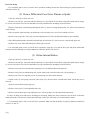
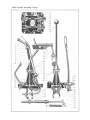
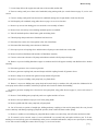
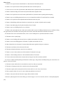
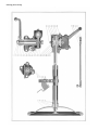
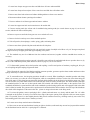
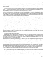
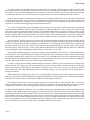
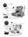
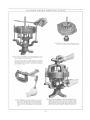
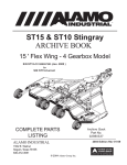
Steering Gear Group
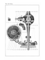
Steering Gear
Ref. No.
I.
2.
3.
4.
5.
6.
7.
8.
9.
10.
11.
12.
13.
14.
15.
16.
17.
18.
19.
20.
21.
22.
23.
24.
25.
26.
27.
28.
29.
30.
31.
32.
33.
34.
35.
36.
37.
38.
39.
40.
41.
42.
43.
44.
45.
46.
Name of Part
Throttle control hand lever
Control cover
Spark hand lever
Horn button
Horn button lock ring
Control cover plate
Horn button spring
Horn button screw
Horn button spring retainer
Horn wire terminal
Horn button contact cup
Stud nut-upper
Friction washer
Jacket tube bushing
Main tube-upper
Steering wheel key
Main tube nut
Sector tube plate
Steering wheel
Spark tube plate
Compression washer
Throttle tube plate
Throttle tube
Spark tube
Horn wire
Sector tube silencer
Sector tube bushing
Stud nut washer
Stud nut-lower
Stud
Control base
Jacket tube cowl bracket
Cowl bracket bolt
Jacket tube
Jacket tube bracket
Jacket tube bracket screw
Spark tube
Throttle tube
Sector tube
Worm wheel and shaft
Worm wheel bushing lock pin
Lock pin retaining wire
Worm wheel bushing
Worm wheel thrust washer-large
Main tube coupling bolt
Coupling bolt nut
(A)
Ref. No.
47.
48.
49.
50.
51.
52.
53.
54.
55.
56.
57.
58.
59.
60.
61.
62.
63.
64.
65.
66.
67.
68.
69.
70.
71.
72.
73.
74.
75.
76.
77.
78.
79.
80.
81.
82.
83.
84.
85.
86.
87.
88.
89.
90.
91.
Name of Part
Case cover gasket
Case cover
Worm wheel thrust washer-small
Thrust washer adjusting screw
Adjusting screw lock nut
Thrust bearing adjusting nut
Adjusting nut felt washer
Main tube coupling
Coupling key
Worm wheel shaft nut
Nut lock
Steering gear lever
Steering gear frame bolt nut
Steering gear bracket spacer
Steering gear frame bracket
Frame bracket bolt
Frame bracket clamp bolt nut
Case cover bolt-short
Case cover bolt-long
Steering case upper bushing
Main tube lower
Upper bushing dowel screw
Main tube lower key
Frame bracket clamp bolt
Sector tube clamp bracket gasket
Sector tube clamp bracket bolt
Throttle tube pinion screw
Throttle tube pinion
Spark tube pinion screw
Spark tube pinion
Sector tube clamp bracket screw
Sector tube clamp bracket
Throttle control sector
Spark control sector
Steering gear case plug
Steering worm
Steering gear case
Thrust bearing
Steering case lower bushing
Control sector shoulder bolt
Drag link
Drag link ball seat
Drag link spring
Drag link plug
Drag link oiler
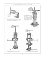
Renew Case and Gear Complete
1. Loosen clamp screws (75, 73) in spark and throttle control pinions and remove pinions (76, 74).
2. Loosen sector tube bracket clamp bolt (72).
3. Disconnect at horn terminal, wire (25) leading from steering gear horn button to horn.
4. Remove screws (36) and cap from jacket tube bracket (35).
[23]
Steering Gear Group
5. Loosen main tube coupling bolts (45).
6. Disconnect upper and lower main tubes (15, 67) by grasping steering wheel and pulling column assembly upward, until
spark tube is clear of lower main tube.
7. Remove bolts (65) from case cover (48), takeoff bracket supporting spark, throttle and oil control rods and levers.
8. Straighten lugs on nut lock (57) and remove nut (56) from worm wheel shaft.
9. Pull steering gear lever (58) off taper on worm wheel shaft, using puller shown on page 18, service tool section.
10. Remove nuts (59) and bolts (62) holding steering gear frame bracket (61) to frame; this will allow the removal of the
lower case and gear assembly.
11. Install new case and gear assembly and reassemble, reversing the above operations.
(B) Renew Upper and Lower Case and Worm Wheel
Bushings, Worm Wheel or Thrust Washers
1 . Loosen clamp screws (75, 73) in spark and throttle control pinions and remove pinions (76, 74).
2. Loosen sector tube bracket clamp bolt (72).
3. Disconnect at horn terminal, wire (25) leading from steering gear horn button to horn.
4. Remove screws (36) and cap from jacket tube bracket (35).
5. Loosen main tube coupling bolts (45).
6. Disconnect upper and lower main tubes (15, 67), by grasping steering wheel and pulling column assembly upward, until
spark tube is clear of lower main tube.
7. Remove bolts (65) from case cover (48), take off bracket supporting spark, throttle and oil control rods and levers.
8. Straighten lugs on nut lock (57) and remove nut (56) from worm wheel shaft.
9. Pull steering gear lever (58) off taper on worm wheel shaft, using puller shown on page 18, service tool section.
10. Loosen frame bracket clamp bolt (70); this will release steering gear lower case and gear assembly, which may now be
removed from the car.
11. Loosen adjusting nut clamp bolt at top of case, unscrew adjusting nut (52) and remove upper bushing lock screw (68);
this will allow the removal of the upper bushing (66), lower main tube (67), thrust bearings (84) and worm (82).
12. Remove sector tube bracket screws (77) and take off sector tube bracket (78) and gasket (71).
13. Remove case cover screws (64), take off case cover (48) and gasket (47); this will allow the removal of the worm wheel
and shaft (40) and thrust washer (44).
14. Remove worm wheel bushing lock pin retainer (42) and lock pin (41); take out worm wheel bushing (43) and replace
with new part.
15. Press out lower case bushing (85) and replace with new part, using arbor press or bushing drift shown on page 19, service tool section.
16. Fit new worm wheel or thrust washers if necessary and reassemble, reversing operations 1 to 13 inclusive, making
sure parts are properly adjusted as detailed in articles “H”, “I” and “J.”
(C)
Renew Jacket Tube Bushings
1. Loosen clamp screw (73, 75) in spark and throttle control pinions and remove pinions (76, 74).
2. Loosen sector bracket clamp bolt (72).
[24]
Steering Gear Group
3. Disconnect at horn terminal, wire (2 5) leading from steering gear horn button to horn.
4. Loosen clamp bolt (70) in steering gear frame bracket (61).
5. Remove jacket tube bracket screws (36) and cap from bracket (35).
6. Grasp spark and throttle control mounting and pull spark, throttle, and sector tubes and horn wire out of steering gear
main tube.
7. Remove nut (17) from top of steering gear upper main tube.
8. Pull steering wheel off upper main tube, using steering wheel puller shown on page 18, service tool section.
9. Slide jacket tube (34) off steering gear main tube; press out or drive out bushings (14) and replace with new parts.
10. Reassemble parts, reversing above operations.
(D) Renew Steering Gear Lever
1. Remove drag link rear end boot, remove cotter pin and takeout rear end adjusting plug; disconnect drag link from
steering gear lever (58).
2. Straighten lugs on worm wheel nut lock (57), remove worm wheel nut (56) and nut lock.
3. Pull steering gear lever (58) off taper on worm wheel shaft, using steering gear lever puller shown on page 18, service
tool section.
4. Install new steering lever and reassemble parts, reversing above operations.
(E) Renew Lower Tube, Worm or Thrust Bearings
1. Loosen spark and throttle control pinion clamp screws (75, 73) and remove pinions (76, 74).
2. Loosen sector tube bracket clamp bolt (72.)
3. Loosen clamp bolt (70) in steering gear frame bracket (61).
4. Disconnect at horn terminal, wire (2 5) leading from steering gear horn button to horn.
5. Remove screws (36) and cap from jacket tube bracket (35).
6. Loosen main tube coupling bolts (45).
7. Disconnect upper and lower main tubes (15, 6 7) by grasping steering wheel and pulling column assembly upward, until
spark tube is clear of lower main tube.
8. Loosen adjusting nut clamp bolt at top of case, unscrew adjusting nut (52) and remove upper bushing lock screw (68).
9. The upper main tube, worm, thrust bearings and upper bushing may be removed and replaced with the new parts where
necessary, and steering gear reassembled, reversing above operations.
(F) Renew Spark or Throttle Levers, Spark, Throttle or Sector Tubes,
Friction Washers, or Column Silencers
1. Loosen spark and throttle control pinion clamp screws (75, 73) and remove pinions (76, 74).
2. Loosen sector tube bracket clamp bolt (72).
[25]
Steering Gear Group
3. Disconnect at horn terminal, wire (25) leading from steering gear horn button to horn.
4. Loosen clamp bolt (70) in steering gear frame bracket (61).
5. Remove jacket tube bracket screws (36) and cap from bracket (35).
6. Grasp spark and throttle control mounting and pull spark, throttle and sector tubes (24, 23, 39) and horn wire out of
steering gear main tube.
7. Unscrew control cover (2) from control mounting and remove horn button assembly (4), horn button lock ring (5), spring
(7); pull out horn wire assembly (25) and insulator (11).
8. Remove lower control cover stud nuts (29), disassemble spark and throttle levers (3, 1), friction washers (13) and control
base (31).
9. The spark, throttle or sector tubes and levers, friction washers, control base or column silencers (26) may now be replaced
with new parts where necessary and steering gear reassembled, reversing above operations.
(G) Renew Control Cover, Horn Button, Spring,
Horn Wire or Compression Plate
1. Unscrew control cover (2) from control mounting; this will allow the removal of the horn button assembly (4), lock ring
(5), spring (7), horn wire (25) and insulator
2. To renew control cover plate (6), or compression plate (21), remove control cover stud upper nuts (12), and disassemble.
3. Replace parts where necessary and reassemble, reversing above operations.
(H) Adjust Column for End Play
1. Loosen adjusting nut clamp bolt at top of steering gear case.
2. Turn adjusting nut (52) to right until all perceptible play is taken up, making sure that adjustment is not tight enough to
cause binding.
3. Tighten adjusting nut clamp bolt.
(I) Adjust Worm Wheel and Shaft for End Play
1. Loosen nut (51) on steering gear worm wheel thrust washer screw.
2. Turn thrust washer screw (50) to right or clockwise just enough to eliminate all end play.
3. Tighten nut (51).
(J) Adjust Worm Wheel and Shaft for
Back Lash or Play
1. Loosen clamp screws (75, 73) in spark and throttle control pinions, and remove pinions (76, 74).
2. Loosen sector tube bracket clamp bolt (72).
3. Loosen clamp bolt (70) in steering gear frame bracket (61).
4. Disconnect at horn terminal, wire (25) leading from steering gear horn button to horn.
[26]
Steering Gear Group
5. Remove screws (36) and cap from jacket tube bracket (35).
6. Loosen main tube coupling bolts (45).
7. Disconnect upper and lower main tubes (15, 67), by grasping steering wheel and pulling column assembly upward,
until spark tube is clear of lower main tube.
8. Remove bolts (65) from case cover (48), take off bracket supporting spark, throttle and oil control rods and levers.
9. Straighten lugs on nut lock (57) and remove nut (56) from worm wheel shaft.
10. Pull steering gear lever (58) off taper on worm wheel shaft, using puller shown on page 18, service tool section.
11. The steering gear lower case and gear assembly may now be removed from the car and the worm wheel bushing lock
pin retainer (42) and lock pin (41) removed.
12. The steering gear case should now be placed in a vise, and the worm wheel bushing (43) adjusted, until only a slight
amount of backlash or play is felt between the teeth of the worm (82) and worm wheel (40). The steering gear worm wheel
bushing adjusting wrench shown on page 19 service tool section, should be used for this operation.
13. After replacing lock pin (41) and lock pin retainer (42) the adjustment should be tested by turning steering gear from
extreme right to left positions to make sure there is no tendency to bind.
14. To reassemble steering gear, reverse operations 1 to 12.
[27]
Drag Link Group
Drag Link
(A) Renew Drag Link Seats, Springs, Adjusting Plugs
or Drag Link Assembly
1. Remove drag link front and rear end boots and cotter pins from adjusting plugs.
2. Unscrew adjusting plugs (90), remove ball seats (88) and springs (89); disconnect drag link from steering arm and
steering gear lever.
3. Replace or clean parts, thoroughly lubricate and reassemble, reversing above operations and adjusting as detailed in
Article “B.”
(B) Adjust Drag Link
1. Remove drag link front and rear end boots and take out cotter pins.
2. When in proper operating position, the drag link adjusting plugs (90) are screwed into the drag link approximately flush
with the outer edge. It is important that this point be watched when reassembling drag link to car or adjusting, as, if the plugs
are screwed in too far, the cushioning effect of the springs (89) to protect the steering gear from road shocks, will be lost. It is
also essential that they be screwed in tar enough to insure a sufficient number of threads engaging and to properly compress
springs. Clean and lubricate parts thoroughly, replace cotter pins and boots.
[28]
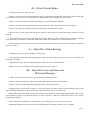
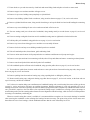
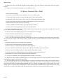
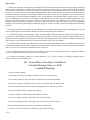
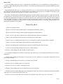
Clutch Group
Hudson Clutch
Ref. No.
1.
2.
3.
4.
5.
6.
7.
8.
9.
10.
11.
12.
13.
14.
Name of Part
Ref. No. Name of Part
Clutch driving disc
Clutch driving stud
Clutch silencing spring
Driving disc cork
Pressure plate
Driven disc
Spring stud
Clutch hub
Clutch pilot bearing
Clutch hub pin
Clutch hub pin nut
Clutch drum screw
Clutch cover
Clutch drum liner
15.
16.
17.
18.
19.
20.
21.
22.
23.
24.
25.
26.
27.
28.
Cover gasket
Silencing spring armed
Driving stud spacer
Drum
Spring retainer
Clutch spring
Spring stud nut
Clutch spider
Cover oil retaining ring
Clutch throwout bearing
Clutch throwout bearing retainer
Oil retaining washer
Throwout yoke
Cover cap screw
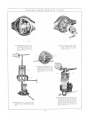
(A) Renew Clutch Assembly, Cover Assembly, Cover Gasket, Pilot Bearing,
Thrust Bearing or Thrust Bearing Retainer
1. Remove toe and floor boards.
2. Remove clevis pin at bottom of hand brake lever and disconnect hand brake pull rod.
3. Remove clevis pin at bottom of brake pedal and disconnect foot brake pull rod.
4. Unscrew sleeve at rear end of speedometer shaft and disconnect speedometer shaft from transmission.
5. Remove bolts from flange of front universal joint and disconnect propeller shaft.
6. Remove clevis pin from lower end of starter pedal shaft lever, disconnect starter operating shaft and spring.
7. Remove cap screws holding transmission case cover to transmission and take off control hand lever assembly.
8. Remove clevis pin from clutch adjustable link and disconnect throwout yoke.
9. Remove bolts holding pedal control bracket to transmission case and take off pedal control assembly.
10. Remove clutch drain plug from flywheel and drain oil out of clutch.
11. Remove cap screws holding clutch cover to flywheel.
12. Remove 3 bolts and 2 cap screws holding transmission case to crankcase, taking out upper bolt last; this will allow the
lowering and removal of the transmission and clutch assemblies from the car. The clutch pilot bearing (9) may now be removed
from the flywheel and renewed if necessary.
13. Remove cotter pin and nut (11) from clutch hub pin (10), take out pin and pull clutch assembly off transmission main
shaft drive gear, using clutch puller shown on page 19, service tool section; this will permit the removal of the clutch assembly,
clutch cover, clutch driving studs, cover gasket, thrust bearing or retainer which may be replaced with new parts as required.
14. Install clutch assembly on transmission and reassemble, reversing above operations.
[31]
Clutch Group
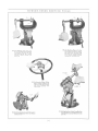
(B) Replace Clutch Plates, Spider, Pressure Plate,
Drum, Springs, Hub or Jaw Liners
1. Remove toe and floor boards.
2. Remove clevis pin at bottom of hand brake lever and disconnect hand brake pull rod.
3. Remove clevis pin at bottom of brake pedal and disconnect foot brake pull rod.
4. Unscrew sleeve at rear end of speedometer shaft and disconnect speedometer shaft from transmission.
5. Remove bolts from flange of front universal joint and disconnect propeller shaft.
6. Remove clevis pin from lower end of starter pedal shaft lever, disconnect starter operating shaft and spring.
7. Remove cap screws holding transmission case cover to transmission and take off control hand lever assembly.
8. Remove clevis pin from clutch adjustable link and disconnect throwout yoke.
9. Remove bolts holding pedal control bracket to transmission case and take off pedal control assembly.
10. Remove clutch drain plug from flywheel and drain oil out of clutch.
11. Remove cap screws holding clutch cover to flywheel.
12. Remove 3 bolts and 2 cap screws holding transmission case to crankcase, taking out upper bolt last; this will allow the
lowering and removal of the transmission and clutch assembly from the car.
13. Remove cotter pin and nut (11) from clutch hub pin (10), take out pin and pull clutch assembly off transmission main shaft
drive gear, using clutch puller shown on page 19, service tool section.
14. Place clutch assembly on clutch assembling fixture shown on page 21, service tool section, or on an arbor press, so that
the clutch will rest on the face of the clutch hub, with the pressure plate on top.
15. Remove cotter pins and nuts (21) from clutch spring studs (7), applying pressure to plate (5) to counteract the pressure of
the clutch springs.
16. The clutch may now be disassembled, and any parts requiring renewal replaced. The plates should be inspected and
renewed if they show signs of being warped, or if the corks are worn down so that there is a possibility of metal to metal contact
between driving and driven plates. It is also advisable to renew the plates if they are excessively loose on driving studs, to avoid
clutch rattle. Reassemble parts, reversing the foregoing operations.
[32]
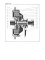
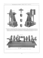
Transmission Group
Hudson Transmission
Ref. No.
1.
2.
3.
4.
5.
6.
7.
8.
9.
10.
11.
12.
13.
14.
15.
16.
17.
18.
19.
20.
21.
22.
23.
24.
25.
26.
27.
28.
29.
30.
31.
32.
33.
Name of Part
Transmission case bolt - long
Mainshaft drive gear
Transmission case
Bearing outer cup lock screw
Mainshaft drive gear outer bearing
Mainshaft front bearing cap gasket
Case bolt nut
Front bearing cap bolt
Mainshaft drive gear inner bearing
Front bearing cap
Front bearing cap felt washer
Mainshaft thrust ball
Mainshaft drive gear key
Mainshaft drive gear steel washer-rear
Mainshaft drive gear bronze washer
Clutch pilot bearing
Mainshaft drive gear steel washer-front
Countershaft bronze washer
Countershaft steel washer
Countershaft
Countershaft bearing cap
Countershaft bearing
Countershaft gear spacer
Countershaft bearing cap screw
Countershaft bearing cap gasket
Countershaft drive gear
Countershaft second speed gear
Transmission case cover gasket
Mainshaft second and high speed gear
Mainshaft front steel washer
Mainshaft
Mainshaft shim
Mainshaft low and reverse gear
Ref. No.
34.
35.
36.
37.
38.
39.
40.
41.
42.
43.
44.
45.
46.
47.
48.
49.
50.
51.
52.
53.
54.
55.
56.
57.
58.
59.
60.
61.
62.
63.
64.
65.
66.
Name of Part
Countershaft gear key
Countershaft low gear
Reverse idler gear
Reverse idler gear bearing
Hand brake ratchet screw
Hand brake ratchet
Reverse idler gear thrust washer
Reverse idler gear shaft
Mainshaft rear bearing
Mainshaft rear bearing cap shim
Mainshaft rear bronze washer pin
Mainshaft rear bearing cap bolt
Mainshaft spacing collar
Speedometer drive gear
Speedometer drive gear washer
Mainshaft steel washer-rear
Mainshaft rear bearing cap
Rear bearing cap felt washer
Rear bearing cap bronze washer
Countershaft bearing shim
Countershaft reverse gear
Clutch throwout yoke
Rear bearing cap oil guide
Mainshaft nut washer
Mainshaft nut
Transmission case bolt-medium
Transmission case bolt-short
Speedometer driven gear bushing
Speedometer driven gear bushing shim
Speedometer driven gear
Oil level test plug
Drain plug gasket
Drain plug
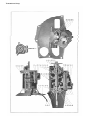
(A) Renew Transmission
1. Remove toe and floor boards.
2. Remove clevis pin at bottom of hand brake lever and disconnect hand brake pull rod.
3. Remove clevis pin at bottom of brake pedal and disconnect foot brake pull rod.
4. Unscrew sleeve at rear end of speedometer shaft and disconnect speedometer shaft from transmission.
5. Remove bolts from flange of front universal joint and disconnect propeller shaft.
6. Remove clevis pin from lower end of starter pedal shaft lever, disconnect starter operating shaft and spring.
7. Remove cap screws holding transmission case cover to transmission and take off control hand lever assembly.
8. Remove clevis pin from clutch adjustable link and disconnect throwout yoke.
9. Remove bolts holding pedal control bracket to transmission case, and take off pedal control assembly.
10. Remove clutch drain plug from flywheel and drain oil out of clutch.
11. Remove cap screws holding clutch cover to flywheel.
[35]
Transmission Group
12. Remove cotter pins and nuts from 3 bolts, take out bolts and 2 cap screws holding transmission case to crankcase, taking
out upper bolt last; this will allow the lowering and removal of the clutch and transmission assemblies from the car.
13. Remove cotter pin and nut from clutch hub pin, take out pin and pull clutch assembly off transmission mainshaft drive
gear, using clutch puller shown on page 19, service tool section, if necessary.
14. Install clutch on new transmission assembly and reassemble, reversing above operations.
(B) Renew Mainshaft, Sliding Gears, Mainshaft Thrust
Ball, Mainshaft Front or Rear Bearings, Mainshaft
Rear Bearing Thrust Washers, or
Speedometer Drive Gear
1. Remove toe and floor boards.
2. Remove clevis pin at bottom of hand brake lever and disconnect hand brake pull rod.
3. Remove clevis pin from lower end of starter pedal shaft lever, disconnect starter operating shaft and springs.
4. Remove cap screws holding transmission case cover to transmission and take off control hand lever assembly.
5. Unscrew sleeve at rear end of speedometer shaft and disconnect speedometer shaft from transmission.
6. Remove bolts from flange of front universal joint and disconnect propeller shaft.
7. Remove cotter pin and nut (58) from rear end of transmission mainshaft and pull off front universal joint flange, using
universal joint flange puller shown on page 22, service tool section.
8. Remove bolts (45) holding mainshaft rear bearing cap (50) and take off cap; this will permit the removal of the mainshaft
and assembled parts.
9. Parts (31, 33, 29, 12, 9, 42, 52,49, or 47) requiring renewal should now be replaced and transmission reassembled, by
reversing above operations. It is very important in reassembling, that the correct number of shims (32) be placed on mainshaft
to allow an end play of from .008” to .012”, when rear bearing cap is tightly bolted in position.
(C) Renew Mainshaft Drive Gear, Mainshaft Outer Bearing,
Mainshaft Drive Gear Thrust Washers, Front Bearing
Cap Felt Washer or Bearing Cap
1. Remove toe and floor boards.
2. Remove clevis pin at bottom of hand brake lever and disconnect hand brake pull rod.
3. Remove clevis pin at bottom of brake pedal and disconnect foot brake pull rod.
4. Unscrew sleeve at rear end of speedometer shaft and disconnect speedometer shaft from transmission.
5. Remove bolts from flange of front universal joint and disconnect propeller shaft.
[36]
Transmission Group
6. Remove clevis pin from lower end of starter pedal shaft lever, disconnect starter operating shaft and spring.
7. Remove cap screws holding transmission case cover to transmission and take off control hand lever assembly.
8. Remove clevis pin from clutch adjustable link and disconnect throwout yoke.
9. Remove bolts holding pedal control bracket to transmission case and take off pedal control assembly.
10. Remove clutch drain plug from flywheel and drain oil out of clutch.
11. Remove cap screws holding clutch cover to flywheel.
12. Remove cotter pins and nuts from 3 bolts, take out bolts and 2 cap screws holding transmission case to crankcase, taking out upper bolt last; this will allow the lowering and removal of the clutch and transmission assemblies from the car.
13. Remove cotter pin and nut from clutch hub pin, take out pin and pull clutch assembly off transmission mainshaft:
drive gear, using clutch puller shown on page 19, service tool section, if necessary.
14. Remove cotter pin, nut (58) and washer from rear end of transmission mainshaft.
15. Pull front universal joint flange off mainshaft, using universal joint flange puller shown on page 22, service tool section.
16. Remove bolts (45) holding mainshaft rear bearing cap to transmission and take off cap (50); this will permit the removal of the mainshaft: (31) and parts assembled on it.
17. Remove bolts (8) holding mainshaft: front bearing cap to transmission and take off cap (10).
18. The mainshaft drive gear (2) and assembled parts may now be removed and renewed where necessary. If outer race of
mainshaft: drive gear outer bearing (5) is to be renewed, mainshaft outer bearing race puller shown on page 15, service tool
section, should be used to remove it from transmission case. To reassemble transmission, reverse the above operations. When
reassembling make sure that from .008” to .012” end play exists in mainshaft, to insure proper lubrication of the thrust washers. Add or remove shims (32) as required, to obtain this end play.
(D) Renew Countershaft Gears, Countershaft,
Countershaft Bearings or Thrust Washers
1. Remove toe and floor boards.
2. Remove clevis pin at bottom of hand brake lever and disconnect hand brake pull rod.
3. Remove clevis pin at bottom of brake pedal and disconnect foot brake pull rod.
4. Unscrew sleeve at rear end of speedometer shaft and disconnect speedometer shaft from transmission.
5. Remove bolts from flange of front universal joint and disconnect propeller shaft.
6. Remove clevis pin from lower end of starter pedal shaft lever, disconnect starter operating shaft and spring.
7. Remove cap screws holding transmission case cover to transmission and take off control hand lever assembly.
8. Remove clevis pin from clutch adjustable link and disconnect throwout yoke.
[37]
Transmission Group
9. Remove bolts holding pedal control bracket to transmission case, and take off pedal control assembly.
10. Remove clutch drain plug from flywheel and drain oil out of clutch.
11. Remove cap screws holding clutch cover to flywheel.
12. Remove cotter pins and nuts from 3 bolts, take out bolts and 2 cap screws holding transmission case to crankcase, taking
out upper bolt last; this will allow the lowering and removal of the clutch and transmission assemblies from the car.
13. Remove cotter pin and nut from clutch hub pin, take out pin and pull clutch assembly off transmission mainshaft drive
gear, using clutch puller shown on page 19, service tool section, if necessary.
14. Remove cotter pin, nut (58) and washer from rear end of transmission mainshaft.
15. Pull front universal joint flange off mainshaft, using universal joint flange puller shown on page 22, service tool section.
16. Remove bolts (45) holding mainshaft rear bearing cap to transmission and take off cap (501); this will permit the removal
of the mainshaft (3 1) and parts assembled on it.
17. Remove screws (24) from countershaft bearing caps, and take off caps (21), shims (53) and bearing rollers and retainers.
18. Pull countershaft bearing outer races out of transmission case, using bearing race puller shown on page 14, service tool
section.
19. Remove countershaft bronze and steel thrust washers (18, 19) and take out countershaft assembly, moving it slightly to
rear and raising front end upward.
20. Countershaft or countershaft gears which require renewal, should now be removed and replaced, using an arbor press.
Renew parts (22, 18, 19) as necessary, and reassemble transmission, reversing the foregoing operations. See that there are
sufficient shims (32) on mainshaft to allow .008” to .012” end play for lubrication, after caps (10, 50) are bolted in place. Shims
(53) should also be added or removed, if necessary, so that from .014” to .018” end play exists in countershaft.
(E) Renew Reverse Idler Gear, Shaft, Bearing
or Thrust Washers
1. Remove toe and floor boards.
2. Remove clevis pin at bottom of hand brake lever and disconnect hand brake pull rod.
3. Remove clevis pin from lower end of starter pedal shaft lever, disconnect starter operating shaft and springs.
4. Remove cap screws holding transmission case cover to transmission and take off control hand lever assembly.
5. Unscrew sleeve at rear end of speedometer shaft and disconnect speedometer shaft from transmission.
6. Remove bolts from flange of front universal joint and disconnect propeller shaft.
7. Remove cotter pin and nut (58) from rear end of transmission mainshaft and pull off front universal joint flange, using
universal joint flange puller shown on page 22, service tool section.
8. Remove bolts (45) holding mainshaft rear bearing cap (50) and take off cap; this will permit the removal of the mainshaft
and assembled parts.
[ 38]
Transmission Group
9. Remove screws (24) holding countershaft rear bearing cap to transmission and take off cap (21).
10. Pull reverse idler gear shaft out of rear of transmission case, by placing 3/8”-16 cap screw in hole tapped in end of
idler shaft and using large screw-driver or piece of flat steel to pry under head of screw.
11. The reverse idler gear (36), bearing (37) and thrust washers (40) may now be removed and renewed where necessary
and transmission reassembled, reversing above operations. Make sure that there is from .008” to .012” end play in mainshaft
after reassembling.
(F)
Renew Transmission Case
1. Remove toe and floor boards.
2. Remove clevis pin at bottom of hand brake lever and disconnect hand brake pull
rod.
3. Remove clevis pin at bottom of brake pedal and disconnect foot brake pull rod.
4. Unscrew sleeve at rear end of speedometer shaft and disconnect speedometer shaft from transmission.
5. Remove bolts from flange of front universal joint and disconnect propeller shaft.
6. Remove clevis pin from lower end of starter pedal shaft lever, disconnect starter operating shaft and spring.
7. Remove cap screws holding transmission case cover to transmission and takeoff control hand lever assembly.
8. Remove clevis pin from clutch adjustable link and disconnect throwout yoke.
9. Remove bolts holding pedal control bracket to transmission case, and take off pedal control assembly.
10. Remove clutch drain plug from flywheel and drain oil out of clutch.
11. Remove cap screws holding clutch cover to flywheel.
12. Remove cotter pins and nuts from 3 bolts, take out bolts and 2 cap screws holding transmission case to crankcase, taking out upper bolt last; this will allow the lowering and removal of the clutch and transmission assemblies from the car.
13. Remove cotter pin and nut from clutch hub pin, take out pin and pull clutch assembly off transmission mainshaft drive
gear, using clutch puller shown on page 19, service tool section, if necessary.
14. Remove cotter pin and nut (58) from rear end of transmission mainshaft and pull off front universal joint flange, using
universal joint flange puller shown on page 22, service tool section.
15. Remove bolts (45) holding mainshaft rear bearing cap (50) and take off cap; this will permit the removal of the mainshaft (31) and assembled parts.
16. Remove bolts (8) holding mainshaft front bearing cap to transmission and take off cap (10); this will allow the removal
of the mainshaft drive gear (2) and assembled parts.
17. Remove screws (24) from countershaft bearing caps, take off caps (21), shims (53) and bearing rollers and retainers.
18. Pull countershaft bearing outer races out of transmission case, using countershaft bearing race puller shown on page
14, service tool section.
19. Remove countershaft bronze and steel thrust washers (18, 19) and take out countershaft assembly, moving it slightly to
rear and raising front end upward.
[39]
Transmission Group
20. Pull reverse idler gear shaft out of rear of transmission case, screwing Y8'-16 cap screw in hole tapped in end of idler
shaft, and using large screw-driver or similar tool to pry under head of screw.
21. Remove reverse idler gear (36), bearing (37) and thrust washers (40).
22. Remove bearing outer sleeve lock screws (4), pull outer sleeves of mainshaft drive gear outer, and mainshaft rear bearings
(5, 42) out of transmission case, using outer sleeve pullers shown on page 14, service tool section.
23. Remove drain and oil level plugs (66, 64), hand brake lever ratchet screws (38) and take off ratchet (39).
24. Replace case with new part and reassemble transmission, reversing above operations. When reassembling transmission
allow .008” to .012” end play in mainshaft and .014” to .018” in countershaft for lubrication of thrust washers.
(G) Renew Clutch Throwout Yoke, Throwout Yoke
Bushing or Bolt
1. Remove cotter and clevis pins from clutch adjustable link and disconnect from throwout yoke (55).
2. Remove cotter pin and nut from bottom of bolt connecting throwout yoke with transmission mainshaft front bearing cap
and take off yoke.
3. Renew yoke or bolt or remove and replace_ bushing in yoke as necessary, and reassemble, reversing above operations.
(H) Renew Mainshaft Rear Bearing Cap Felt Washer
1. Remove bolts from flange of front universal joint and disconnect propeller shaft.
2. Remove cotter pin and nut (58) from rear end of transmission mainshaft and pull off front universal joint flange, using
universal joint flange puller shown on page 22, service tool section.
3. Remove and replace felt washer (51) with new part and reassemble, reversing above operations.
(I) Remove End Play from Mainshaft
End play in the transmission mainshaft, which will develop after extensive service due to wear of the thrust washers, can be
taken up by the removal of shims, as detailed below. In event the end play is very great, due to the thrust washers cutting or
burning out on account of lack of lubrication, it will be necessary to fit new thrust washers. To renew front thrust washers (15,
17) it will be necessary to dismount clutch and transmission assemblies as outlined in Article “C.” If the rear bearing thrust
washers (52, 49) require renewal, proceed as outlined in Article “B.”
1. Remove bolts from flange of front universal joint and disconnect propeller shaft.
2. Unscrew sleeve at rear end of speedometer shaft and disconnect speedometer shaft from transmission.
3. Remove cotter pin, nut (58) and washer from rear end of transmission mainshaft and pull off universal joint flange, using
universal joint flange puller shown on page 22, service tool section.
4. Remove screws (45) holding mainshaft rear bearing cap to transmission and take off cap (50).
[40]
Transmission Group
5. Remove sufficient shims (43) to take out all but from .008” to .012” end play; this amount is essential to insure
lubrication of the thrust washers.
6. Reassemble parts, reversing the above operations.
(J) Remove End Play from Countershaft
The proper end play in the countershaft of the Hudson transmission ranges from .014” to .018”. End play in excess of this
amount may be removed by the addition of shims placed between the countershaft rear bearing cap and rear bearing outer
sleeve, as detailed below.
1. Remove screws (24) from countershaft rear bearing cap and take off cap (21).
2. Add sufficient shims (53) between bearing and cap to allow the end play above mentioned, replace cap and tightly bolt
in place.
[41]
Hudson Pedal Control
Ref. No.
1.
2.
3.
4.
5.
6.
7.
8.
9.
Name of Part
Brake pull rod
Brake pedal adjusting screw
Pedal adjusting screw lock nut
Clutch pedal spring
Clutch pedal retaining pin
Pedal support bracket
Pedal pad screw
Pedal pad
Clutch pedal
Ref. No.
10.
11.
12.
13.
14.
15.
16.
17.
Name of Part
Brake pedal
Pull rod clevis pin
Clutch pedal shaft lever
Pedal shaft
Clutch pedal adjusting yoke
Adjusting yoke clevis pin
Stationary yoke clevis pin
Stationary yoke
Pedal Control
Group
(A) Renew or Rebush Pedal Support Bracket,
Clutch or Brake Pedal
1. Remove toe and floor boards.
2. Remove clevis pin (11) from bottom of brake pedal (10) and disconnect foot brake pull rod.
3. Remove clevis pin (16) from clutch adjusting link (17) and disconnect clutch throwout yoke.
4. Remove screws holding pedal support bracket (6) to transmission. case and take off pedal control assembly.
5. Unhook clutch pedal spring (4) from support bracket.
6. Drive out taper pin (5) at lower end of clutch pedal and pull pedal (9) off pedal shaft.
7. The pedal shaft (13) and lever (12) may now be withdrawn from support bracket and the brake pedal (10) removed.
8. The brake pedal and pedal support bracket should be rebushed or renewed as necessary, and parts reassembled by
reversing the above operations.
[45]
Hand Control Assembly Group
Hand Control Assembly
Ref. No.
Name of Part
1. Hand brake lever latch screw
2. Hand brake lever latch
3. Latch rod end
4. Latch rod nut
5. Latch rod
6. Hand brake lever
7. Gearshift lever cover pin
8. Gearshift lever spring
9. Gearshift lever cover
10. Starter pedal
11. Control lock plunger
12. Hand brake lever latch rod spring
13. Control housing gasket
14. Housing cap screw
15. Hand brake lever ratchet spring
16. Starter shaft retaining pin
17. Starter shaft
18. Starter shaft lever
19. Starter shaft lever clevis pin
20. Gearshift lever spring seat
21. Gearshift lever felt washer
22. Gearshift lever ball cup
23. Control housing
24. Control lock
25. Control lock retaining pin
26. Control housing pin
27. Gearshift lever key
28. Oil filler plug
Ref. No.
Name of Part
29. Oil filler plug gasket
30. Starter shaft collar screw
31. Collar screw lock wire
32. Starter gear shaft
33. Starter shaft washer
34. Transmission case cover
35. Transmission case cover screw
36. Shifter shaft lock ball spring cap
37. Shifter shaft lock ball spring
38. Shifter shaft lock ball
39. Low and reverse shifter shaft
40. Inner lock plunger
41. Second and high speed shifter shaft
42. Gearshift lever ball
43. Gearshift lever
44. Hand brake lever spring washer
45. Pivot stud nut
46. Pivot stud
47. Brake lever latch clevis pin
48. Latch pivot stud
49. Latch pivot stud nut
50. Latch single end
51. Latch double end
52. Shifter fork lock screw
53. Low and reverse shifter fork
54. Second and high speed shifter fork
55. Starter shaft rod
56. Starter operating spring
(A) Renew Gearshift Lever, Cover, Spring, Ball Cup,
Felt Washer or Lever Key
1. Remove ball (42) from top of gearshift lever (43).
2. Drive taper pin (7) out of gearshift lever cover (19).
3. Remove cover (9) spring (8) spring seat (20) and felt washer (21), unscrew gearshift lever ball cup (22).
4. Remove lock wire from gearshift lever pin (26) and pull out pin, this will allow the removal of the gearshift lever and
key (27).
5. Any of the above parts requiring renewal should be replaced and control reassembled, reversing above operations.
(B) Repair or Renew Control Lock or Plunger
1. Remove toe and floor boards.
2. Remove cotter and clevis pins from lower part of brake hand lever and disconnect hand brake pull rod.
3. Remove clevis pin (19) from bottom of starter shaft lever and disconnect starter operating shaft rod (55) and spring (56).
[49]
Hand Control Assembly Group
4. Remove transmission case cover screws (35) and take control hand lever assembly off transmission.
5. Remove screws (14) holding control housing to transmission case cover. Take off control housing (23) and assembled
parts.
6. The control lock (24) is secured to the control housing (23) by means of a dowel pin (25) in diameter, which passes
through the housing and enters a hole drilled in the lock. The pin is then fastened in place by welding to the housing. To
remove the lock it is first necessary to chip out the metal surrounding the weld with a sharp cold chisel so that the dowel pin
is exposed. This pin is next drilled out, using a drill and drilling to a depth not to exceed 9/16” from outside of housing. In
performing this operation, it is important that the drill be accurately centered, otherwise all of the pin will not be removed, and
the lock will not be released.
7. The lock may then be removed and repaired or replaced as necessary, together with plunger (11).
8. To reassemble, fit new dowel pin, weld in place and reverse above operations.
(C) Renew Transmission Case Cover, Shifting Forks,
Shifting Shafts and Interlock Plungers
1. Remove toe and floor boards.
2. Remove cotter and clevis pins from lower part of brake hand lever and disconnect hand brake pull rod.
3. Remove clevis pin (19) from bottom of starter shaft lever and disconnect starter operating shaft rod (55) and spring
(56).
4. Remove transmission case cover screws (35) and take control hand lever assembly off transmission.
5. Remove cotter pin, nut (45) and spring washer (44) from brake hand lever pivot and take off brake hand lever (6).
6. Remove screws (14) holding control housing to transmission case cover, take off control housing (23) and assembled
parts.
7. Remove oil filler plug (28) and gasket (29).
8. Remove cotter pin and clevis pin (16) holding starter pedal shaft in place.
9. Drive taper pin out of bottom of starter pedal (10) pull. starter pedal shaft (17 out of pedal.
10. Remove lock wires and lock screws (52) from gear shifting forks (53, 54).
11. Remove shifting shaft lock spring caps (36) springs (3 7) and lock balls (38).
12. Slide shifting shafts (39, 41) out of shifting forks and transmission case cover and remove interlock plungers (40).
13. Renew parts where necessary and reassemble control lever assembly, reversing the above operations.
(D) Renew Control Housing
1. Remove toe and floor boards.
2. Remove cotter and clevis pins from lower part of brake hand lever and disconnect hand brake pull rod.
3. Remove clevis pin (19) from bottom of starter shaft lever and disconnect starter operating shaft rod (55) and spring
(56).
.[50]
Hand Control Assembly Group
4. Remove transmission case cover screws (35) and take control hand lever assembly off transmission.
5. Remove screws (14) holding control housing to transmission case cover, take off control housing and assembled parts
6. Remove ball (42) from top of gear shift lever (43).
7. Drive taper pin (7) out of gear shift lever cover (9).
8. Remove cover (9), spring (8), spring seat (20) and felt washer (21), unscrew gear shift lever ball cup (22).
9. Remove lock wire from gear shift lever pin (26) and pull out pin, this will allow the removal of the gear shift lever and
key (27).
10. The control lock (24) is secured to the control housing (23) by means of a dowel pin (25), 3/16” diameter, which passes
through the housing and enters a hole drilled in the lock. The pin is then fastened in place by welding to the housing. To
remove the lock, it is first necessary to chip out the metal surrounding the weld with a sharp cold chisel, so that the dowel pin
is exposed. The pin is next drilled out, using a 3/16” drill and drilling to a depth not to exceed 9/16” from outside of housing.
In performing this operation, it is important that the drill be accurately centered, otherwise all of the pin will not be removed,
and the lock will not be released.
11. The control lock end plunger (11) may now be removed and fitted to new housing and parts reassembled, reversing the
foregoing operations.
[51]
Universal Joints and Propeller Shaft Group
Hudson Universal Joints and
Propeller Shaft
Ref. No.
Name of Part
Ref. No.
1. Casing plug
2. Companion flange-rear
3. Flange bolt nut-rear
4. Flange bolt nut lock-rear
5. Flange bolt-rear
6. Outer casing spring
7. Outer casing spring retainer
8. Spring retainer bolt
9. Spring retainer bolt nut
10. Propeller shaft
11. Dust cap felt washer disc
l2. Dust cap felt washer
13. Dust cap
14.
15.
16.
17.
18.
19.
20.
21.
22.
23.
24.
25.
(A)
Name of Part
Sleeve yoke
Cross
Outer casing
Bushing
Outer casing packing
Inner casing
Flange bolt-front
Flange bolt nut lock front
Flange bolt nut-front
Bushing retaining ring
Companion flange-front
Flange yoke
Renew Front Universal Joint
1. Straighten lugs on nut locks (21), remove nuts from flange bolts (2), take out bolts and disconnect front joint from
transmission flange (24).
2. Unscrew dust cap (13) from sleeve yoke (14) and slide front universal joint off propeller shaft.
3. Slide dust cap (13), dust washer (12) and disc (11) off front end of shaft and replace with corresponding parts of new
universal joint.
4. If the front companion flange (24) requires renewal, remove cotter pin and nut from rear end of transmission main shaft
and pull flange off mainshaft, using universal joint flange puller shown on page 22, service tool section.
Fit new flange to transmission shaft, tapping same in place with a lead or rawhide hammer; replace washer, then tighten and
cotter pin nut securely.
5. Oil splines in sleeve yoke of new joint and place on propeller shaft, making sure that the arrow on the sleeve yoke lines
up with the arrow on the front end of the propeller shaft.
6. Fill joint with fibre grease through opening in front end, then place in position and bolt to flange, bending over ears on
nut locks after thoroughly tightening nuts.
(B) Renew Propeller Shaft, Universal Joint Flange or
Sleeve Yokes, Crosses, Bushings, Inner
or Outer Casings
1. Bend back ears on nut locks (4, 21), remove universal joint flange bolt nuts (3, 22) and take out flange bolts (5, 20), this
will allow the removal of the shaft and joints.
2. Unscrew dust cap (13) from sleeve yoke (14) of front universal joint; pull front joint assembly off propeller shaft.
3. To renew front or rear universal joint parts, place joint or propeller shaft on bench and remove nuts (8) from spring
retainer bolts (9); this will permit the removal of the retainers (7), springs (6), outer casings (16) and inner casings (19), which
parts may be slipped over the shaft.
[55]
Universal Joints and Propeller Shaft Group
4. Drive bushings (17) from flange yokes (25) with drift or hammer and separate yokes from crosses (15).
5. Pry out lock rings (23) holding bushings in place in propeller shaft rear yoke and front sleeve yoke, using a screwdriver
or similar tool which must be forced between the bushing and lock ring; this will allow the remaining bushings to be driven out,
releasing the crosses (15).
6. Renew propeller shaft, flange or sleeve yokes, crosses, bushings or casings as necessary, and reassemble parts, reversing
the foregoing operations. When installing assembled shaft in position, be sure that the arrow stamped on the propeller shaft (10)
at the front end, lines up with the arrow stamped on the sleeve yoke (14) of the front universal joint, also that the joints are
thoroughly lubricated.
(C) Renew Rear Universal joint Assembly and
Propeller Shaft
1. Straighten ears on rear universal joint flange bolt nut locks (4), remove nuts (3), take out flange bolts (5) and disconnect
rear end of the propeller shaft.
2. Remove dust cap (13) from sleeve yoke of front joint and pull propeller shaft out of sleeve yoke.
3. The rear universal joint companion flange (2) should now be removed from the rear axle pinion shaft if renewal is
necessary. Remove cotter pin and nut from front end of shaft and pull off flange, using universal joint flange puller shown on
page 22, service tool section. Remove all dirt and foreign matter from taper on shaft and flange and tap flange in place with a
soft hammer. Replace washer, draw up pinion shaft nut tightly and spread cotter pin.
4. Clean splines at front end of new shaft and slide shaft in sleeve yoke of front joint, placing parts in position so the arrows
stamped on the front of the propeller shaft and universal joint are in line with each other.
5. The rear universal joint should then be lubricated with fibre grease, and tightly bolted to the rear companion flange,
after which the nut locks should be bent over to guard against the parts coming loose.
[56]
Carburetor Group
Hudson Carburetor
Ref. No.
1.
2.
3.
4.
5.
6.
7.
8.
9.
10.
11.
12.
13.
14.
15.
16.
17.
18.
19.
20.
21.
22.
23.
24.
25.
26.
Name of Part
Ref. No.
Adjusting shaft lever spring
Gear housing screw
Strainer plug gasket
Strainer plug
Adjusting shaft lever
Bell crank link
Bell crank clevis pin
Bell crank
Gasoline pipe union
Adjusting shaft lever clamp screw
Adjusting shaft lever swivel
Adjusting shaft lever swivel screw
Adjusting screw pawl
Adjusting screw
Adjusting screw pawl spring
Throttle body
Aspirating nozzle
Throttle body cap screw
Air valve cone
Throttle body gasket
Carburetor body
Air valve stem
Float needle valve cap
Float cover screw
Float weight axle
Float weight
(A)
27.
28.
29,
30.
31.
32.
33.
34.
35.
36.
37.
38.
39.
40.
41.
42.
43.
44.
45.
46.
47.
48.
49.
50.
51.
52.
Name of Part
Adjusting shaft gland
Adjusting shaft lock nut
Adjusting shaft packing nut
Adjusting shaft
Adjusting shaft packing
Throttle shaft packing
Butterfly screw
Butterfly valve
Throttle shaft
Metering pin
Gear housing
Gear housing gasket
Metering pin rack
Metering pin spring
Float needle valve
Needle valve seat
Filter screen
Gear housing cap
Gear housing cap gasket
Throttle shaft lever adjusting screw
Adjusting screw lock screw
Throttle shaft lever
Bell crank spring
Body plug
Clamp nut
Inlet elbow assembly
Renew Carburetor
1. Shut off gasoline valve at bottom of vacuum tank and disconnect gasoline feed pipe at carburetor.
2. Disconnect accelerator rod at carburetor bell crank.
3. Disconnect mixture and throttle control wires at carburetor.
4. Remove set screw at carburetor air inlet at take off carburetor hot air pipe.
5. Remove three screws holding carburetor to inlet manifold and take off carburetor assembly.
6. Replace with new carburetor assembly, reversing above operations and fitting new gasket when bolting carburetor to inlet
manifold.
(B) Renew Float Cover, Float Cover Weights, Float
Needle Valve, Float Assembly, or Needle Valve Seat
1. Remove float chamber cover screws and take off cover assembly, float needle valve and float.
2. If float needle valve seat requires renewal, it should be removed from the carburetor body by means of a hexagon socket
wrench, and replaced with a new part. The parts removed in operation 1, should be replaced with new parts where necessary
and reassembled.
(C) Renew Air Valve, Cone, Air Valve Stem,
or Aspirating Nozzle
1. Shut off gasoline valve at bottom of vacuum tank and disconnect gasoline feed pipe at carburetor.
2. Disconnect mixture control wire from lever at bottom of carburetor.
[59]
Carburetor Group
3. Remove cap screws (18) holding carburetor body to throttle body. This will release the lower carburetor assembly which
may be placed on the workbench for further repairs.
4. Remove lower screws (2) holding gear housing to carburetor body, disconnect adjusting shaft lever spring (1) and remove
gear housing from carburetor body.
5. Turn carburetor body assembly upside down and place in vise holding upper end of air valve cone (19) on flat faces,
being careful not to spring cone out of shape.
6. Unscrew air valve stem and piston (22) from air valve cone (19) using special carburetor wrench having two small pins
which engage holes drilled in the bottom of the piston.
7. This will release the aspirating nozzle (17) which, together with the cone and stem, may be renewed if necessary. It is
advisable before reassembling, to make sure that the ball check valves in the bottom of the air valve stem move freely in their
seats as if they are rusted or stuck in the seats the carburetor action will be sluggish. The air valve cone should also be inspected
to make sure that the low speed air inlet holes are free from dirt.
(D)
Clean Carburetor
1. Shut off gasoline valve at bottom of vacuum tank and disconnect gasoline feed pipe at carburetor.
2. Disconnect mixture and throttle control wires at carburetor.
3. Disconnect accelerator rod at carburetor bell crank.
4. Remove set screw at carburetor air inlet and take off carburetor hot air pipe.
5. Remove three screws holding carburetor to inlet manifold and take off carburetor assembly.
6. Thoroughly clean carburetor with a stiff brush and gasoline so there will be no danger of dirt working into the inside of
the carburetor when it is disassembled. .
7. Remove float chamber cover screws (24), take off float chamber cover assembly, float and needle valve.
8. Remove strainer from bottom of float chamber, unscrewing strainer plug (4) or union nut (51).
9. Remove cap screws (18) from carburetor body and take off throttle body assembly (16).
10. Remove screws (2) holding gear housing (37) to carburetor body and take off ear housing.
11. The carburetor body and disassembled parts may now be thoroughly cleaned in gasoline and blown out with compressed
air, if available. Be sure that the openings through the needle valve seat, from float chamber to dashpot chamber and through
air valve stem and aspirating nozzle are perfectly clean and free of obstructions which might hinder the flow of gasoline through
these parts. Also make certain that the low speed air inlet holes in the air valve cone (19) are open, and that the adjusting pinion
and metering pin assembly operate smoothly in the gear housing. The ball check valves in the bottom of the air valve stem (22)
should be examined to make sure they are free to move up and down.
12. On account of their accurately machined surfaces, it is important when cleaning the air valve stem, metering pin and
component parts, that no abrasives, files or emery cloth be used, otherwise the carburetor will not function properly when
reassembled.
13. After all parts have been properly cleaned, the carburetor should be reassembled by reversing the operations listed
above. When doing this be particularly careful to
[60]
Carburetor Group
see that the metering pin and air valve are free to slide up and down in the carburetor body in all positions of rotation. It is also
advisable, if the carburetor has been in service for some time, to renew strainer plug gasket (3), throttle body gasket (20), and
gear housing gasket (8), in addition to slightly tightening packing nut (29) surrounding the pinion shaft.
(E) Renew Gear Housing, Metering Pin Assembly,
Adjusting Shaft and Pinion, Gland or Packing
1. Shut off gasoline by turning valve at bottom of vacuum tank, and unscrew gasoline feed pipe at carburetor.
2. Disconnect mixture control wire at carburetor adjusting lever (5).
3. Remove set screw holding carburetor hot air pipe to carburetor; take off pipe.
4. Remove cap screws (18) holding throttle body to carburetor body and take off lower carburetor assembly.
5. Unscrew gear housing cap (44) and remove metering pin spring (40).
6. Unhook adjusting shaft lever spring (1), remove gear housing screws (2) and take off gear housing assembly.
7. Loosen clamp screw (10) on adjusting shaft lever and pull lever off shaft.
8. Unscrew adjusting shaft gland (27) from gear housing, this will allow the removal of the shaft and pinion (30), also
metering pin and rack (36). Renew gear housing or component parts where necessary and reassemble parts as follows:
9. Replace metering pin and rack assembly in gear housing.
10. Assemble pinion and shaft in gland; tighten packing and lock nuts (29, 28), and screw assembled parts in gear housing,
meshing adjusting pinion with rack on metering pin.
11. Replace gear housing and parts, fitting new gasket between housing and carburetor body and tightening the screws.
12. Grasp end of adjusting shaft between fingers and turn shaft slowly to the left or anti-clockwise so the metering pin (36),
will be forced up into the air valve (22), lifting it up from its seat in the carburetor body. (If the shaft turns too stiffly to be moved
by the fingers, the lever (5) may be slipped on the end of the shaft and used as a wrench.)
13. Next turn the adjusting shaft in the opposite direction or to the right, very slowly until the air valve just touches the seat.
When in this position, measurement should be taken of the distance between the bottom face of the metering pin rack (39), and
the bottom face of the gear housing (37), against which the cap (44) seats. This can be done with a narrow scale or depth gauge
inserted in the opening in which the rack operates.
14. The adjusting shaft should then be turned slightly further to the right so the bottom of the metering pin rack will be
lowered 1/16” as measured by the scale.
15. Carefully slide adjusting shaft lever off end of shaft so the position of the shaft will not be disturbed; then turn adjusting
screw (14) up or down as necessary so it will be in the center of its travel.
Then replace lever on shaft so the top edge of the lever will be just even with the bottom of the adjusting screw.
16. Tighten clamp screw (10) on lever and hook spring (1) in position. Make sure packing nut (29) is not too tightly adjusted
to prevent the spring from keeping lever (5) against the screw.
[61]
Carburetor Group
17. Replace spring (40) in the bottom of metering pin rack and screw gear housing cap (44) on gear housing.
18. To complete the reassembling of the carburetor reverse operations 1 to 4 inclusive, using a new gasket between
carburetor body and throttle body. After the motor has been run sufficiently to become warmed up the final adjustment of the
carburetor should be made by turning the screw (5).
[62]
Motor Group
Ref. No.
1.
2.
3.
4.
5.
6.
7.
8.
9.
10.
11.
12.
13.
14.
15.
16.
17.
18.
19.
20.
21.
22.
[64]
Name of Part
Flywheel bolt nut
Flywheel bolt
Flywheel drain plug
Flywheel
Starter-generator base adjusting plug
Starter-generator base bolt
Starter-generator base
Oil reservoir gasket
Oil reservoir
Generator cutout relay
Generator strap
Generator
Carburetor bolt
Carburetor gasket
Cylinder side plate
Cylinder side plate nut
Carburetor
Distributor bracket gasket
Water pump body to cylinder screw
Water pump body to cylinder gasket
Fan support arm clamp bolt
Fan arm stud
Ref. No.
23.
24.
25.
26.
27.
28.
29.
30.
31.
32.
33.
34.
35.
36.
37.
38.
39.
40.
41.
42.
43.
44.
Name of Part
Timing advance arm
Distributor stud nut
Oil pump body cap
Oil pump body cap gasket
Timing arm link
Oil pump body plug
Oil pump body union elbow
Oil pump inlet connection gasket
Oil pump body stud nut
Oil pump inlet connection
Oil pump inlet connection elbow
Fan support arm
Fan spider
Fan spindle nut
Spark advance cross tube
Water outlet manifold
Water outlet manifold cap screw
Water outlet manifold gasket
Cylinder head nut
Ignition coil bracket
Ignition coil
Fan pulley
Motor Group
Hudson Motor
Ref. No.
45.
46.
47.
48.
49.
50.
51.
52.
53.
54.
55.
56.
57.
Name of Part
Starting crank guide
Fan belt
Starting crank jaw
Crankcase front cover
Crankcase front cover screw
Crankcase front cover gasket
Spark advance cross tube lever lock
Spark advance cross tube lever
Spark advance cross tube bracket
Spark advance bracket cap screw
Cylinder to crankcase gasket
Horn wire bracket
Oil control rocker shaft
Ref. No.
58.
59.
60.
61.
62.
63.
64.
65,
66.
67.
W
69.
70.
Name of Part
Oil control rocker shaft lever
Oil control rocker shaft lever lock
Cylinder drain cock
Oil gauge glass cap
Oil gauge glass
Oil level indicator
Oil filler vent
Oil filler cover
Cylinder to crankcase stud nut
Oil filler cover screw
Oil filler cover spring
Flywheel pointer
Flywheel pointer screw
[65]
Motor Group
Motor Group
Hudson Motor.
Ref. No.
71.
72.
73.
74.
75.
76.
77.
78.
79.
80.
81.
82.
83.
84,
85.
86.
87.
88.
89.
90.
91.
92.
93.
94.
95.
96.
[66]
Name of Part
Exhaust manifold
Tappet adjusting screw
Tappet adjusting screw nut
Exhaust manifold packing nut
Cylinder to crankcase stud
Cylinder to crankcase stud nut
Tappet guide clamp
Tappet adjusting screw plate
Cylinder head stud
Cylinder head gasket
Exhaust manifold gasket
Cylinder block
Valve spring
Valve spring seat
Cylinder side plate stud
Starter shaft front bushing
Starter gears
Starter shaft rear bushing
Starter operating shaft
Starter switch
Starting motor
Starting motor strap
Inlet manifold gasket
Inlet manifold stud-short
Inlet manifold stud-long
Inlet manifold
Ref, No.
97.
98.
99.
100.
101.
102.
103.
104.
105.
106.
107.
108.
109.
110.
111.
112.
113.
114.
115.
116.
117.
118.
119.
120.
121.
122.
Name of Part
Generator coupling
Generator coupling bolt
Generator coupling clamp
Generator coupling bolt nut
Water pump packing nut-rear
Water pump shaft
Water pump drain cock
Crankcase
Water pump body bolt nut
Water pump body gasket
Water pump body bolt
Water pump cover
Eccentric body gasket
Eccentric body
Water pump body to crankcase bolt
Water pump packing nut-front
Water pump body
Water pump grease cup
Distributor assembly
Timing arm clamp screw
Oil pipe clip
Oil pump suction pipe
Oil pump adjusting shaft bearing
Oil pump and drive gear housing
Oil pump and drive gear housing screw
Oil pump and drive gear housing gasket
Motor Group
(A) Remove Carbon, Grind Valves, Renew Cylinder
Head, Cylinder Head Gasket, Valves or Valve Guides
1. Drain water out of cooling system.
2. Loosen rear hose clamp on upper water hose.
3. Remove nuts holding water outlet manifold to cylinder head and take off manifold.
4. Disconnect horn wires at terminals on horn, remove screws holding horn to cylinder head and take off horn.
5. Disconnect wires at spark plugs.
6. Remove screws holding cable tube and wires to cylinder head and take off cable tube.
7. Remove acorn nuts holding ignition coil bracket to cylinder head and take off coil.
8. Shut off gasoline valve at bottom of vacuum tank and disconnect gasoline feed pipe at carburetor.
9. Disconnect accelerator rod at carburetor bell crank.
10. Disconnect throttle and mixture control wires at carburetor.
11. Remove set screw from carburetor air inlet and take off carburetor hot air pipe.
12. Remove 3 bolts holding carburetor to inlet manifold and take off carburetor.
13. Remove nuts from cylinder side plate studs and take off cylinder side plates.
14. Remove nuts from cylinder head studs and take off cylinder head and cylinder head gasket, prying up evenly on opposite
sides. The cylinder head as well as the tops of the pistons, valves and cylinder block may now be cleaned of carbon deposits by
scraping or by means of a wire carbon-removing brush operated by an electric drill. It is advisable when doing this, to stuff rags
in the cylinders on top of the pistons to prevent particles of carbon from getting between the pistons and cylinder walls.
15. Compress valve springs either singly or by means of multiple valve lifters, remove valve spring retainers and take out
valves. Insert valve stems through holes drilled in a board in their order of removal from the cylinder block, to prevent them be
coming mixed.
16. If valve guides require renewal, drive old guides out of cylinder block with a drift or piece of brass rod. Insert new guides,
using valve stem guide puller shown on page 20, service tool section, to draw them into position. After installing, they should be
reamed to size, using valve stem guide reamer shown on page 11, service tool section.
17. Thoroughly clean valves of carbon with wire brush or by other means, also clean inside of valve stem guides. Note
carefully the condition of the seats on the valves and cylinder block; if they are at all badly pitted, a great deal of time will be
saved and a far better job will be done by having the valve faces ground true on a valve refacing machine, and the seats refaced
in the cylinder block. On page 17, service tool section, will be found equipment specially designed to cover this class of work,
the use of which will greatly expedite valve grinding operations. After the valves and cylinder block have been refaced, or if the
valves have been renewed, a slight grinding-in is necessary to insure a perfect seat; this is done as follows:
18. Crank the engine, if necessary, to make sure that the cam operating the valve to be ground is not holding the valve off its
seat. Spread a thin coating of valve grinding compound, either water or oil mixed, on the face of the valve (a fine grade should
be used). Place a light open coil spring over the valve stem and insert valve in position
[67]
Motor Group
in cylinder block. This spring should be of sufficient size and tension to just keep the valve off the cylinder block. Rotate valve
on seat from right to left with a semi-circular movement, using an electric or hand operated valve grinder or by means of a screw
driver held in the slot in the valve head. It is very important when doing this, that the head of the valve be frequently raised and
turned around half a revolution to guard against cutting grooves in the valve and seat. When the grinding has been properly done,
the valves and seats will have a silvery color throughout their entire circumference. After the grinding has been completed be
sure to clean valves and cylinder to remove all traces of grinding compound.
19. Replace valves in their respective positions and insert spring seats and retainers.
20. Replace cylinder head, using new cylinder head gasket. When tightening cylinder head nuts, start at the center and work
toward the ends, alternating on each side and with uniform pressure on the wrench. After the engine has been run and thoroughly
warmed up, the nuts should again be drawn up tight.
21. Complete reassembling of motor by reversing operations 1 to 12 inclusive. The motor should then be run and warmed up,
after which the tappets should be readjusted to allow a clearance of from .002" to .003" minimum on the inlet valves and .004"
to .005" minimum on the exhaust valves. Replace cylinder side plates, using new gaskets if necessary, and tightening nuts
sufficiently to prevent oil leaks without springing the side plates out of shape.
(B) Renew Valve Spring, Seat, Retainer, or
Tappet Adjusting Screw
1. Remove cylinder side plate stud nuts, take off cylinder side plates.
2. Raise valve with valve lifter and remove valve spring retainer.
3. Remove valve spring, seat, and tappet adjusting screw; renew parts where necessary.
4. Reassemble parts, reversing the foregoing operations. Before replacing the cylinder side plates adjust intake valve tappets
to .002” to .003” clearance minimum, and exhaust valve tappets to .004” to .005” clearance, with hot motor.
(C) Renew Valve Tappet, Tappet Guide,
Tappet Roller or Roller Pin
1. Drain water out of cooling system.
2. Loosen rear hose clamp on upper water hose.
3. Remove nuts holding water outlet manifold to cylinder head and take off manifold.
4. Disconnect horn wires at terminals on horn, remove screws holding horn to cylinder head and take off horn.
5. Disconnect spark plug wires at spark plugs.
6. Remove screws holding cable tube and wires to cylinder head and take off cable tube. coil 1, Remove acorn nuts holding
ignition coil bracket to cylinder head and take off
8. Shut off gasoline valve at bottom of vacuum tank and disconnect gasoline feed pipe at carburetor.
[68]
Motor Group
9. Disconnect accelerator rod at carburetor bell crank.
10. Disconnect throttle and mixture control wires at carburetor.
11. Remove set screw from carburetor air inlet and take off carburetor hot air pipe.
12. Remove 3 cap screws holding carburetor to inlet manifold and take off carburetor.
13. Remove nuts from cylinder side plate studs and take off cylinder side plates.
14. Remove nuts from cylinder head studs and take off cylinder head and gasket, prying up evenly on opposite sides.
15. Compress valve springs with valve lifter, remove valve spring retainers and take out valves, valve springs and seats.
16. Remove nuts from cylinder studs and take off tappet guide clamps.
17. The valve tappet assemblies may now be lifted out of position, and any parts which require renewal should be replaced.
When removing the valve tappet assemblies, it is advisable to leave the adjusting screws, lock nuts and plates screwed into the
tappets to preclude the possibility of the tappets dropping out of the guides and into the interior of the motor. It is extremely
important when replacing tappet guides in the cylinder block, that the locating washers which fit over the cylinder studs, rest in
the proper semi-circular grooves in the flanges of the guides.
If this is not done, the rollers will not ride squarely on the cams, and destruction of the camshaft and tappet mechanism will
result. When the guides are installed correctly in the cylinder, the flat surfaces on the flanges will be exactly at right angles to
the center line of the motor.
18. The motor should be reassembled by reversing operations 1 to 12, and 14 to 16 inclusive. After allowing the motor to run
until warmed up, the tappets should be adjusted to .002” to .003” clearance minimum on the inlet valves, and .004” to .005”
clearance on the exhaust valves. Replace cylinder side plates, fitting new gaskets, if necessary.
(D) Renew Inlet or Exhaust Manifold, Inlet or Exhaust
Manifold Gaskets, or Exhaust Manifold Packing Nut
1. Remove machine screw holding carburetor air heater to inlet manifold.
2. Remove set screw from carburetor body and take off hot air pipe and air heater.
3. Disconnect vacuum tank suction pipe at inlet manifold.
4. Remove machine screws and clamp plate from inlet manifold and disconnect mixture control wire tube.
5. Remove 3 cap screws holding carburetor to inlet manifold.
6. Remove nuts from inlet manifold studs and take off inlet manifold and gasket.
7. Unscrew exhaust manifold packing nut out of exhaust manifold, using spanner wrench shown on page 26, service tool
section.
8. Remove nuts from exhaust manifold studs and take off exhaust manifold.
9. Replace with new parts where necessary, fitting new packing to exhaust manifold and reassemble, reversing the above
operations.
[69]
Motor Group
(E) Renew Distributor Drive and Oil Pump Support,
Rebush or Renew Distributor Drive Bracket, Renew
Oil Pump Drive Worm, Oil Pump Eccentric,
Eccentric Shaft, Distributor Drive Shaft
or Driven Gear
1. Unhook spring clamps on distributor and lift off distributor cap and wires.
2. Disconnect low tension wire from ignition coil at side of distributor.
3. Disconnect link from timing advance arm on distributor.
4. Remove nuts from distributor studs and take off distributor assembly.
5. Unscrew union nuts at bottom and side of oil pump and disconnect oil pump suction and pressure gauge pipes.
6. Remove nuts holding oil pump to distributor support and take off oil pump assembly.
7. Drive taper pin out of coupling and disconnect oil pump eccentric shaft from oil control rocker shaft.
8. Remove nuts from studs holding distributor support to crankcase and take off support assembly.
9. If the oil pump eccentric and gear or the eccentric shaft require renewal, remove cap screws and cap which will permit
the removal of these parts.
10. The distributor shaft, gears, and bracket assembly may now be lifted off and disassembled for the replacement of the shaft,
gears, or to rebush the bracket, by removing cotter pin and nut at bottom of shaft. To rebush bracket, drive out old bushings with
a drift or piece of 1/8” steel rod and press new bushings in place on arbor press or by tapping with a hammer and block. To secure
perfect alignment and correct size, the bushings should be line reamed after pressing in place, with distributor shaft line reamer
shown on page 11, service tool section.
11. To reassemble motor, reverse the operations listed above. When replacing the distributor drive shaft and bracket
assembly, it is important that the teeth on the distributor shaft driven gear be meshed with the water pump shaft so the slot in the
distributor drive washer points directly toward the front of the car, when No. 1 cylinder is on upper dead center on the firing
stroke.
After reassembling distributor to motor, it will be necessary to re-time the ignition, as follows:
12. Fully advance spark, pulling spark lever on steering wheel down to lowest position.
13. Remove spark plug from No. 1 cylinder and crank motor by hand until the rush of air indicates that the piston is coming
up on compression stroke. This can be determined by placing finger over spark plug opening.
14. Crank motor very slowly until the pointer on the observation hole (on the left side of the flywheel case) is directly over
the center of the mark "A" which is stamped on the flywheel.
It is permissible to time slightly ahead of this point if found necessary. Results should be checked on the road and spark retarded
slightly if there is any tendency to knock.
15. Loosen clamp screw on timing arm at bottom of distributor.
[70]
Motor Group
16. Place rotor on cam and turn distributor housing to right or clockwise, until metal strip on rotor has just passed the terminal
on the distributor head to which No. 1 spark plug wire is fastened.
17. Remove rotor from cam and turn distributor housing slightly to left or anticlockwise, until contact points just begin to
separate.
18. Tighten clamp screw on timing arm and replace rotor and distributor head.
(F) Renew Timing Sprockets, Chain, Gear Case Cover,
Cover Gasket, Camshaft, Camshaft Thrust Washer,
Thrust Button, Thrust Spring, Generator Sprocket
Stationary or Floating Coupling or Thrust Washer
1. Remove bonnet assembly.
2. Open drain cock at bottom of water pump cover and drain water out of cooling system.
3. Loosen hose clamp at front of upper and lower radiator hose.,
4. Disconnect radiator shutter operating rod at radiator.
5. Remove nuts from bolts holding radiator assembly to frame.
6. Unscrew radiator tie rod from upper radiator tank and lift off radiator assembly.
7. Loosen clamp bolt on fan support arm and remove fan assembly and fan belt.
8. Unscrew starting crank jaw at front end of crankshaft, using starting crank jaw wrench shown on page 23, service tool
section.
9. Unscrew starting crank guide from front end of crankshaft, turning same in right hand or clockwise direction.
10. Pull fan pulley off crankshaft, using puller shown on page 19, service tool section.
11. Remove cap screws from timing gear cover and take cover assembly off motor.
12. Remove lock wire and cap screws holding camshaft sprocket to camshaft.
13. Take off camshaft sprocket, thrust button, guide and timing chain.
14. Remove nuts from cylinder side plate studs and take off cylinder side plates.
15. Raise valves and tappets and hold in wide open position by means of multiple valve lifters or by Y4' hexagon nuts placed
on edge between top of valve tappet guides and tappet adjusting screw plates.
16. The camshaft may now be withdrawn from the crankcase and renewed, together with the camshaft thrust washer, as
necessary.
17. If the crankshaft sprocket requires renewal, it should be removed from the crankshaft and the new sprocket driven on, by
the use of the crankshaft sprocket puller and driver shown on page 23, service tool section.
18. To disassemble pump shaft sprocket and coupling, cut off riveted-over portion of stationary coupling pin, drive pin out
of coupling and pull coupling off generator shaft.
This will permit the removal of the floating coupling, generator sprocket, generator sprocket thrust washer and thrust washer
springs, which may be replaced with new parts if required.
[71]
Motor Group
19. The motor may be reassembled after renewing necessary parts, by reversing the foregoing operations. When replacing the
camshaft sprocket and timing chain, it is very important that the following points be observed regarding the relation of the
distributor and camshafts to the crankshaft, so the valves and ignition will be properly timed:
Turn water pump shaft until the metal strip on the top of the rotor points directly toward the front of the car.
Turn camshaft until exhaust valve has just closed and inlet valve is just about to open on No. 6 cylinder.
Turn crankshaft until No. 1 and No. 6 pistons are on upper dead center.
On the side of the chain facing the front of the motor, will be found arrows stamped on the links which should point in the
direction in which the motor runs. Upon close observation, 2 punch marks will be seen on the link pins which are exactly 18
links apart. The chain should be placed on the camshaft sprocket so that one of these punch marks will coincide with similar
punch marks on the sprocket teeth, while the other punch mark lines up with the marked teeth on the crankshaft sprocket. Be
careful not to materially change the position of the distributor shaft when doing this.
After the reassembling has been completed, it is necessary to re-time the ignition, as follows:
20. Fully advance spark, moving spark lever on steering wheel down to lowest position.
21. Crank motor very slowly with No. 1 cylinder on the compression stroke, until the pointer on the observation hole (on the
left side of the flywheel case) is directly over the center of the mark “A” which is stamped on the flywheel. The spark may be
set slightly in advance of this point if deemed necessary, checking results on the road and retarding ignition if the motor shows
a tendency to knock.
22. Adjust contact points to .020” gap at wide open position.
23. Loosen clamp screw on timing arm at bottom of distributor.
24. Place rotor on cam and turn distributor housing to right or clockwise, until the terminal on the distributor head to which
No. 1 spark plug wire is fastened, has just passed the metal strip on the top of the rotor.
25. Remove rotor from cam and turn housing slightly to left or anti-clockwise, until contact points just begin to separate.
26. Tighten clamp screw on timing arm and replace rotor and distributor head.
(G) Rebush or Renew Adjusting Eccentric Body, Water
Pump Body, Water Pump Cover, Water Pump
Paddle, Water Pump Shaft, or Water
Pump Shaft Rear Thrust Washer
1. Remove bonnet assembly.
2. Open drain cock at bottom of water pump cover and drain water out of cooling system.
3. Loosen hose clamps at front of upper and lower radiator hose.
4. Disconnect radiator shutter operating rod at radiator.
5. Remove nuts from bolts holding radiator assembly to frame.
6. Unscrew radiator tie rod from upper radiator tank and lift off radiator assembly.
[72]
Motor Group
7. Loosen clamp bolt on fan support arm and remove fan assembly and fan belt.
8. Unscrew starting crank jaw at front end of crankshaft, using starting crank jaw wrench shown on page 23, service tool
section.
9. Unscrew starting crank guide from front end of crankshaft, turning same in right hand or clockwise direction.
10. Pull fan pulley off crankshaft, using puller shown on page 19, service tool section.
11. Remove cap screws from timing gear cover and take cover assembly off motor.
12. Remove lock wire and cap screws holding camshaft sprocket to camshaft.
13. Take off camshaft sprocket, thrust button, guide and timing chain.
14. Unhook spring clamps and remove distributor head and wires.
15. Disconnect low tension wire from ignition coil at side of distributor.
16. Disconnect link from timing arm at bottom of distributor.
17. Drive taper pin out of coupling sleeve and disconnect oil pump eccentric shaft from rocker shaft.
18. Remove nuts from distributor studs and take off distributor assembly.
19. Unscrew union nuts at bottom of oil pump and crankcase and take off oil pump suction pipe.
20. Remove cap screws holding distributor support to crankcase and lift off support assembly and distributor drive bracket
assembly.
21. Disconnect generator wire at cutout on generator.
22. Remove generator coupling bolts, nuts and clamps and slide coupling forward off generator sleeve.
23. Remove clamp screw and nut from generator strap and take off generator.
24. Remove 2 cap screws holding water pump body to cylinder block.
25. Remove 3 cap screws holding water pump body and eccentric body to crankcase; this will permit the withdrawal of the
water pump and eccentric assemblies, which may be placed on the bench for further disassembling.
26. Remove generator coupling sleeve from end of water pump shaft, using puller shown on page 19, service tool section, if
necessary.
27. Remove 5 bolts holding water pump body and cover together and take off cover.
28. Remove cotter pin and drive taper pin out of water pump paddle.
29. Remove paddle and slide water pump body off pump shaft.
30. Cut off riveted-over portion of straight pin, holding stationary coupling to front end of pump shaft, drive out pin and
remove stationary and floating couplings, pump shaft sprocket, thrust washer and thrust washer springs.
31. Remove 3 machine screws holding rear pump shaft thrust washer to eccentric body, take off washer and remove shaft.
32. If eccentric is to be renewed, remove 3 screws which hold it to eccentric body and replace with new part. To fit new
bushing to rear end of body, press out old bushing n arbor press or with drift and hammer, and press new part in place, reaming
to size with eccentric bushing line reamer shown on page 11, service tool section.
[ 73 ]
Motor Group
33. Rebush or renew water pump body or cover if necessary. New bushings should be reamed to size after pressing in place,
with expansion reamer shown on page 11, service tool section. Any other parts which require renewal should now be replaced,
and the motor reassembled, which is accomplished by reversing the above operations. When replacing distributor drive shaft and
bracket assembly, it is important that the gear teeth on the water pump shaft and the distributor driven gear be meshed so the slot
in the distributor drive washer at the top of the distributor shaft points directly toward the front of the motor when No. 1 cylinder
is on upper dead center on the firing stroke.
This can be determined by placing a finger over No. 1 spark plug hole and cranking the motor by hand until the rush of air
indicates that the piston is coming up on compression stroke. To insure correct timing of the valves, it is necessary, when
replacing the camshaft sprocket and timing chain, that the following points be closely observed: The side of the chain facing the
front of the motor has arrows stamped on the links, which must point in the direction in which the chain runs. Upon close
observation, 2 punch marks will be seen on the link pins which are exactly 18 links apart. Place chain on camshaft sprocket so
that one of these punch marks will coincide with similar punch marks on the sprocket teeth. The crankshaft should then be turned
until the tooth on the crankshaft sprocket bearing punch marks, will engage the other link in the chain which is likewise marked.
After the reassembling has been completed, it will be necessary to re-time the ignition, as follows:
34. Fully advance spark, moving spark lever on steering wheel down to lowest position.
35. Crank motor very slowly with No. 1 cylinder on the compression stroke, until the pointer on the observation hole (on the
left side of the flywheel case) is directly over the center of the mark "A" which is stamped on the flywheel.
The spark may be set slightly in advance of this point if deemed necessary, checking results on the road and retarding ignition
if the motor shows a tendency to knock.
36. Loosen clamp screw on timing arm at bottom of distributor.
37. Adjust contact points to .020” gap at wide open position.
38. Place rotor on cam and turn distributor housing slightly to right or clockwise, until the terminal on the distributor head to
which No. 1 spark plug wire is fastened, has just passed the metal strip on. the top of the rotor.
39. Remove rotor from cam and turn housing slightly to left or anti-clockwise, until contact points just begin to separate.
40. Tighten clamp screw on timing arm and replace rotor and distributor head.
After replacing the timing chain and camshaft sprocket, and before replacing the 3 bolts which hold the water pump and
eccentric bodies to the crankcase, the chain must be adjusted. This is done by engaging the eccentric adjusting wrench shown on
page 26, service tool section, with the notches on the eccentric flange and pulling wrench toward workman until only 1/8”
backlash or play is visible when the coupling is grasped by the hand and rocked back and forth.
(H) Renew Generator Assembly
1. Disconnect wire at terminal on cutout relay or on top of generator.
2. Remove nuts, bolts, and clamps from generator coupling and slide coupling forward on shaft.
3. Loosen clamp screw on generator strap and remove generator from base.
4. Fit new generator assembly in place, after scraping excess paint off outside portion resting in base to insure a good ground
contact. Slide coupling back, replace clamps and bolts and tighten nuts. The clamp screw in the generator strap should then
[74]
Motor Group
be drawn up securely. Upon completion of the installation of the generator, the alignment should be checked. If it is found that
the front end of the generator is not concentric with the drive shaft it should be lined up by loosening the 3 cap screws holding
starter-generator base in position.
This will allow any misalignment in a sidewise direction to be corrected; if the front end of the generator is too high or low,
the forward cap screw should be removed entirely and the adjusting plug, through which the screw passes, moved up or down as
necessary, using generator adjusting wrench shown on page 20, service tool section. When proper alignment has been secured,
tighten the cap screws in the base.
(I)
Renew Distributor Assembly
1. Pull spark plug and ignition coil high tension wires out of terminals on distributor head.
2. Disconnect low tension wire from ignition coil at side of distributor.
3. Remove nut from ball joint and disconnect link at spark advance arm on distributor.
4. Remove nuts from distributor studs and lift off distributor assembly.
5. Install new distributor assembly, and reassemble parts, reversing the above operations. When replacing high tension wires
on distributor head, No. 1 spark plug wire must be fitted to the terminal nearest the front of the motor, followed, in right hand or
clockwise order, by. wires leading to No. 5, No. 3, No. 6, No. 2, and No. 4 spark plugs. The ignition must then be re-timed as
follows:
6. Place finger over spark plug opening in No. 1 cylinder and crank motor until the rush of air indicates that the piston is
coming up on compression stroke.
7. Fully advance spark, pulling spark lever on steering wheel down to lowest position.
8. Crank motor very slowly until the pointer on the observation hole (on the left side of the flywheel case) is directly over the
center of the mark “A” which is stamped on the flywheel. The motor can be timed slightly in advance of this point if necessary,
checking results on the road and retarding spark if there is any tendency to knock.
9. Loosen clamp screw on timing arm at bottom of distributor.
10. Place rotor on cam and turn distributor housing to right or clockwise, until metal strip on rotor has just passed the terminal
on the distributor head to which No. 1 spark plug wire is fastened.
11. Remove rotor from cam and turn housing slightly to left or anti-clockwise, until contact points just begin to separate.
12. Tighten clamp screw on timing arm and replace rotor and distributor head.
(J) Renew Pistons, Piston Pins, Piston Rings, Piston Pin
Bushings, Connecting Rods or Connecting Rod Bearings
1. Place receptacle under oil reservoir, remove oil reservoir drain plug and drain oil.
2. Raise up front end of car with chain hoist or axle stands, remove oil reservoir cap screws and take off oil reservoir.
3. Drain water out of cooling system.
4. Loosen rear hose clamp on upper water hose.
[75]
Motor Group
5. Remove nuts holding water outlet manifold to cylinder head and take off manifold.
6. Disconnect horn wires at terminals on horn, remove screws holding horn to cylinder head and take off horn.
7. Disconnect spark plug wires at spark plugs.
8. Remove screws holding cable tube and wires to cylinder head and take off cable tube.
9. Remove acorn nuts holding ignition coil bracket to cylinder head and take off coil.
10. Shut off gasoline valve at bottom of vacuum tank and disconnect gasoline feed pipe at carburetor.
11. Disconnect accelerator rod at carburetor bell crank.
12. Disconnect throttle and mixture control wires at carburetor.
13. Remove set screw from carburetor air inlet and take off carburetor hot air pipe.
14. Remove 3 bolts holding carburetor to intake manifold and take off carburetor.
15. Remove tappet cover stud nuts and take off tappet covers.
16. Loosen fan support arm clamp bolt and remove fan assembly.
17. Unscrew exhaust manifold packing nut and loosen exhaust pipe in exhaust manifold, using exhaust manifold packing nut
wrench shown on page 26, service tool section.
18. Remove 2 cap screws holding water pump body to cylinder.
19. Remove nuts holding cylinder block to crankcase, using wrenches shown on page 17, service tool section.
20. Remove spark plugs and screw motor lifting eyes, shown on page 17 service tool section, into No. 1 and 6 spark plug holes.
21. Raise cylinder block from crankcase, using chain hoist or block and tackle and motor lifting chain. The motor must be in
a level position when doing this and the cylinder rocked back and forth slightly, which will assist in its removal, after which it
should be placed on the work bench for piston fitting, etc.
22. Remove cotter pins and nuts from connecting rod bolts, take off caps and shims and remove connecting rods and pistons.
23. Remove piston pin lock rings from pistons, using piston pin lock ring remover shown on page 17, service tool section.
24. Before removing the piston pins, the pistons should be heated to a temperature of approximately 200 degrees or as hot as
can be handled with gloves, using a piston pre-heating stove, electric or gas plate, or other means. The pins can then readily be
removed without danger of damaging or breaking the pistons.
25. When replacing pistons, it is advisable to measure the cylinder bores with a cylinder indicator of the type shown in
equipment section, to determine whether they are worn excessively out of round or tapered. If this condition exists, or if the bores
are scored or damaged, they should be trued up with a cylinder hone or grinder, making them uniform in size and removing only
enough stock to enable the next oversize piston to be used. A complete list of piston sizes furnished by the factory, together with
their markings, will be found in reference sheet No. 18. New pistons should be fitted to the cylinder bores with a clearance of
.003" to .004", and must be installed on the connecting rods so the sawcut or split in the skirt, will face the left side of the cylinder
or the side opposite the valves.
[76]
Motor Group
26. To renew piston pins, a long piloted spiral expansion piston pin reamer similar to that shown on page 11, service tool
section, should be used.
The reaming of the piston pin bushing in the connecting rod is best done by holding the connecting rod in a vise with the piston
pin bushing in a vertical position, using a tap wrench of the type illustrated on page 26, service tool section, to turn the reamer.
This generally produces more satisfactory results than holding the reamer in the vise and revolving the connecting rod around it,
in which case there is a possibility of reaming the bushing bell-mouthed, due to the weight of the big end of the rod and the natural
tendency of the mechanic to exert a downward pressure on the rod when turning it.
When fitting new piston pins to pistons, it is essential that the piston pin bosses be finished reamed approximately .002” under
the diameter of the piston pins, to guard against looseness when the motor is heated up in operation. For this reason it is also
necessary, when assembling the pins, that the pistons be preheated as outlined above.
27. To renew piston rings, place connecting rod in vise or secure piston in piston vise while removing or replacing rings. On
page 25, service tool section, are shown a piston vise and piston ring spreader, which facilitate this work. Thoroughly clean ring
grooves in piston of carbon and foreign matter and test fit of new rings in grooves. They should be of the proper width to slide
freely in the piston grooves without perceptible play or looseness. If the rings are too wide it will be necessary to carefully dress
them down until the above fit is obtained. This is best done by fastening the new ring to a small flat board into which a number
of small brads are driven in a circle, so the heads project from the board slightly less than the width of the ring.
A sheet of No. 0 or No. 1/2 emery cloth should then be laid on a surface plate, and the board, with the ring attached, is moved
back and forth with a light, even pressure of the hand. It is important when doing this, that the ring be occasionally turned around
to insure removing an equal amount of metal on all sides, and also that the square edges of the ring are not removed. After the
rings have been properly fitted to the piston grooves, any burrs on the faces should be removed, and the slots or gaps fitted to the
cylinder bores.
Place piston without rings in cylinder with the bottom or open end outward, then place ring to be fitted in cylinder,
straightening the ring by bringing the edge of the piston against it.
The slot clearance or gap should then be accurately measured with a feeler gauge and, if necessary, the edges of the ring
dressed with a thin, smooth file until the opening measures from .006” to .008”, after which they should be placed on their
respective pistons.
28. To renew connecting rod bearings, proceed as follows:
Remove machine screws holding connecting rod bearings to rod and cap and take out bearings.
Fit new bearings to connecting rod and cap, making sure that no burrs or chips prevent the screws from drawing the bearings
firmly into position.
File edges of the bearings down flush with the connecting rod and cap. This must be carefully done to prevent the surfaces of
the rod and cap from being filed away.
Place an equal number of shims on each connecting rod bolt and replace cap on rod in proper position as indicated by numbers
stamped on side of rod and cap, then securely tighten nuts on connecting rod bolts; (the combined thickness of the total number
of shims on each side of the rod should be approximately .125”).
After new bearings have been installed in the connecting rod and cap, the sides of the bearings or thrust faces must be finished
so the overall width will be from .008” to .010” less than the distance between throws on the crankshaft. To insure an accurate
job this should be done with a thrust bearing facing cutter; however a file may be used to dress the bearings if care is exercised
[77]
Motor Croup
to get the width uniform at all points. The use of the telescoping gauge and micrometers shown on pages 27, 24, service tool
section, will facilitate finishing the bearings to the proper dimensions so the end play mentioned above, which is necessary for
lubrication, will be maintained.
Fitting the connecting rod bearings to the crankshaft is best done by means of a connecting rod bearing reamer, either of the
adjustable or solid type shown on page 24, service tool section. With ordinary care a satisfactory bearing can be obtained by the
use of this tool in far less time than that required by hand scraping. If no reamer is available and it is necessary to scrape the
bearing in, proceed as follows:
Connecting rod bearings may be scraped to fit the crankshaft or an accurately machined arbor which is the same diameter as
the crankshaft. Separate cap from rod and spread a thin coating of Prussian blue on the crankshaft or arbor, then replace shims
and draw up cap tight. Rock connecting rod back and forth on the shaft a few times, then remove cap and examine bearings. The
blue marks on the bearings indicate the points of contact with the shaft and must be removed by scraping. This must be very
carefully done so that a very thin shaving of metal will be removed from the blued spots on the bearings.
After all of these "high spots" have been scraped down, the shaft should again be blued and the connecting rod cap tightened.
Remove cap from rod after rocking rod on shaft and repeat scraping process described above. This should be done as many times
as necessary, until the bearings finally show a fine series of spots, close together and uniformly distributed over the entire surface.
When properly fitted, the connecting rod bearings will be from .001' to .0015' larger than the crankpins, and it is essential that
this clearance be maintained when assembling the connecting rods to the crankshaft to provide space for an oil film.
29. When new connecting rod bearings or piston pin bushings have been installed or bearings fitted, it is necessary that the
connecting rods be tested for alignment, as a satisfactory job cannot be done unless the piston pins are perfectly parallel with the
crankshaft in all directions, and the proper clearance exists between the upper ends of the rods and the bosses on the inside of the
pistons. On page 10, service tool section, a connecting rod aligning fixture is shown which enables a proper check of rod
alignment to be made with a minimum expenditure of time and labor. When using a fixture of this type, it is advisable to remove
the piston from the connecting rod before checking the alignment, as the varying diameters of the lands and skirt, together with
the extensive relief surrounding the piston pin boss, do not afford a good contact between the side of the piston and the aligning
disc on the fixture. If the connecting rods are found to be bent or twisted when checked on the aligning fixture, it will be necessary
to straighten them with a bending iron until the contact plate, which is fitted to the upper end of the rod, touches the aligning disc
at all points. The connecting rod bending iron illustrated on page 20, service tool section, will be found indispensable when doing
this work.
30. Reassemble pistons to connecting rods after aligning has been completed, heating the pistons and placing them on the rods
so the diagonal split in the skirt will be on the left side when assembled in position in the motor.
31. Assemble connecting rods and pistons to crankshaft, after thoroughly cleaning bearings and shaft and spreading a film of
oil on the surfaces. When doing this, be sure that a sufficient number of shims is used to allow a clearance of approximately .001'
for lubrication when the cap bolts are drawn up tight. Connecting rod bearings adjusted with this clearance will fit the crankshaft
just tight enough to prevent the rods and pistons from falling sidewise when placed in a vertical position. It is essential, when
doing this work, that all of the connecting rods be adjusted evenly as the additional friction of one bearing adjusted tighter than
the others would prevent smooth and quiet operation. Make sure that all of the nuts are securely cotter pinned after adjustment is
completed.
[78]
Motor Group
32. Examine cylinder block to crankcase gasket and replace with a new one if necessary, shellacking it to the crankcase.
33. Thoroughly clean cylinder bores, pistons and piston rings, and spread a film of oil over them, turning the rings in the
grooves in the pistons until the slots are 120 degrees apart.
34. Fasten cylinder to chain hoist or block and tackle as outlined in operations 20 and 21, suspending block in perfectly level
position. Maneuver position of car if necessary, so the cylinder block will be directly over the pistons; then turn crankshaft until
No. 1 and No. 6 pistons are on upper dead centers.
35. Clean the lower face of the cylinder block and top of the crankcase of all dirt or chips, and -slowly lower block in position,
using piston ring compressors shown on page 25, service tool section, to compress the rings and guide the pistons into the
cylinders. After No. 1 and 6 pistons have entered the cylinder block, the crankshaft should be turned slightly and the block
lowered over No. 2 and 5 pistons. Repeat this for No. 3 and 4 pistons and lower block to crankcase.
Too much stress cannot be laid upon the necessity for careful handling during this operation, as it is easily possible to set up
strains which would spring the connecting rods, thereby offsetting any accurate aligning which may have been done.
36. Securely tighten nuts holding cylinder block to crankcase, using wrenches shown on page 17, service tool section. Make
sure that the tappet guide locating washers are placed over the studs in the valve compartment before replacing the tappet guide
clamps and also that the guides themselves are in the proper position before tightening the nuts. When the tappet guides are
correctly installed the flat surfaces on the flanges are exactly at right angles to the crankshaft.
37. The reassembling of the motor may be completed by reversing operations 1 to 18 inclusive, fitting new gaskets where
necessary and new packing at exhaust pipe to manifold joint.
38. Inspect clearance between tappet adjusting screws and valve stems and adjust if necessary. After the assembling of the
motor has been completed, it should be run long enough to attain a normal operating temperature, after which the tappets should
be adjusted to .002” to .003” clearance on the intake valves, and .004” to .005” clearance on the exhaust valves.
(K) Renew Motor Assembly, Crankshaft, or Camshaft
Bearings; Renew or Refit Crankshaft Bearings
1. Remove bonnet assembly.
2. Open drain cock at bottom of water pump cover and drain water out of cooling -system.
3. Loosen hose clamps at front of upper and lower radiator hose.
4. Disconnect radiator shutter operating rod at radiator.
5. Remove nuts from bolts holding radiator assembly to frame.
6. Unscrew radiator tie rod from upper radiator tank and lift off radiator assembly.
7. Loosen clamp bolt on fan support arm and remove fan assembly and fan belt. Remove toe and floor boards.
[79]
Motor Group
9. Remove clevis pin at bottom of hand brake lever and disconnect hand brake pull rod.
10. Remove clevis pin at bottom of brake pedal and disconnect foot brake pull rod.
11. Unscrew sleeve at rear end of speedometer shaft and disconnect speedometer shaft from transmission.
12. Remove bolts from flange of front universal joint and disconnect propeller shaft.
13. Remove clevis pin from lower end of starter pedal shaft lever, disconnect starter operating shaft and spring.
14. Remove cap screws holding transmission case cover to transmission and take off control hand lever assembly.
15. Remove clevis pin from clutch adjustable link and disconnect throwout yoke.
16. Remove bolts holding pedal control bracket to transmission case, and take off pedal control assembly.
17. Remove clutch drain plug from flywheel and drain oil out of clutch.
18. Remove cap screws holding clutch cover to flywheel.
19. Remove cotter pins and nuts from 3 bolts, take out bolts and 2 cap screws holding transmission case to crankcase, taking
out upper bolt last; this will allow the lowering and removal of the clutch and transmission assemblies from the car.
20. Disconnect horn wires at terminals on horn, remove screws holding horn to cylinder head and take off horn.
21. Disconnect wires at spark plugs.
22. Remove screws holding cable tube and wires to cylinder head and take off cable tube.
23. Remove acorn nuts holding ignition coil bracket to cylinder head and take off coil.
24. Shut off gasoline valve at bottom of vacuum tank and disconnect gasoline feed pipe at carburetor.
25. Disconnect accelerator rod at carburetor bell crank .
26. Disconnect throttle and mixture control wires at carburetor.
27. Remove set screw from carburetor air inlet and take off carburetor hot air pipe.
28. Remove 3 bolts holding carburetor to inlet manifold and take off carburetor.
29. Unscrew union nut and disconnect vacuum tank suction pipe from elbow at intake manifold.
30. Unscrew exhaust manifold packing and disconnect exhaust pipe, using exhaust manifold packing nut wrench shown on
page 26, service tool section.
31. Disconnect starter cable and wires at terminals on starter base and top of generator.
32. Disconnect oil gauge pressure tube at union between oil pump and dash.
33. Disconnect spark and oil control pull rods from rocker shaft levers (52, 58) at front of motor.
34. Place receptacle under oil reservoir, remove drain plug and drain out motor oil.
35. Remove cotter pins and nuts from motor support bolts and take out bolts.
36. Remove spark plugs and screw motor lifting eyes shown on page 17, service tool section, into No. 1 and 6 spark plug holes.
[80]
Motor Group
37. Fasten hooks to eyes and raise motor by chain hoist and motor lifting chain and place on bench or motor stand.
38. Remove tappet cover stud nuts and take off tappet covers.
39. Remove 2 cap screws holding water pump body to cylinder block.
40. Remove nuts holding cylinder block to crankcase, using wrenches shown on pages 17, 20, service tool section.
41. Remove cylinder block from motor, being careful when doing so to keep the block level and avoid bending the connecting
rods.
42. Remove cap screws holding oil reservoir to crankcase and take off oil reservoir.
43. Unscrew starting crank jaw at front end of crankshaft, using starting crank jaw wrench shown on page 23, service tool
section.
44. Unscrew starting crank guide from front end of crankshaft, turning same in right hand or clockwise direction.
45. Pull fan pulley off crankshaft, using puller shown on page 19, service tool section.
46. Remove cap screws from timing gear cover and take cover assembly off motor.
47. Remove lock wire and cap screws holding camshaft sprocket to camshaft.
48. Take off camshaft sprocket, thrust button, guide and timing chain.
49. Unscrew union nuts at bottom of oil pump and union on crankcase and disconnect oil pump suction pipe.
50. Remove cotter pins and nuts from connecting rod bolts, take off caps and shims and remove connecting rods and pistons.
51. Remove nuts from flywheel bolts and take flywheel off crankshaft.
52. Pull crankshaft sprocket off front end of crankshaft, using sprocket puller shown on page 23, service tool section.
53. Turn crankcase upside down in motor stand and remove cotter pins and nuts from main bearing cap studs, using wrench
shown on page 24, service tool section.
54. Remove packing from front and rear bearing caps, using a packing hook or drilling the packing out.
55. Remove main bearing caps, using main bearing cap puller shown on page 27, service tool section, on the front and rear
caps if necessary, and lift out crankshaft.
56. For the service station doing even a small amount of crankshaft bearing work, a main bearing line reamer of the type shown
on page 31, service tool section, will prove an excellent investment. With this equipment, it is not only possible to fit a set of
bearings in a fraction of the time required by the laborious hand scraping method, but a comparatively unskilled mechanic can turn
out a job which is superior to the best efforts of an experienced bearing scraper. In addition to securing a greater percentage of
actual bearing surface, the line reaming method insures accurate alignment of all the bearings, which is a factor of vital importance
in turning out a satisfactory and lasting job.
Whenever a main bearing line reamer is available it is recommended that a complete set of new main bearings be installed
when renewing the crankshaft or when refitting f the bearings becomes necessary. The great saving of time in such cases more
than offsets the cost of new bearings, with the additional assurance that the work will stand up in service.
[81]
Motor Group
57. Before reaming or scraping in the main bearings, it is necessary that the crankhaft be carefully inspected for trueness and
out of round crankpins and journals, as well as for rough surfaces on these parts. If any of these defects exist, they must obviously
be corrected by straightening, grinding or polishing, if a satisfactory job is to be done. On page 16, service tool section, a surface
plate, vee blocks and dial indicator are shown, which make it easy to readily detect a sprung crankshaft. Crankpins and journals
can be checked for roundness with a 2” to 3” micrometer, taking measurements at various points around the circumference.
Following is the method of procedure when renewing main bearings:
58. Remove countersunk head machine screws holding bearings to caps and crankcase and take out bearings.
59. Remove all burrs, dirt and chips from crankcase and backs of new bearings, and fit bearings to crankcase and caps. After
firmly tightening the screws drawing the bearings into place, it is necessary that the projecting edges be filed perfectly even with
the crankcase or caps. The bearing filing blocks shown on page 27, service tool section, will save a great deal of time and labor
when doing this operation, as it is possible to file the bearings accurately to size before installing them in crankcase.
60. In event no line reamer is at hand and the bearings are to be scraped in, the thrust faces on the center rear main bearing
should be filed down so there will be .006' end play when the crankshaft is in position. If the bearings are to be line reamed, this
operation can be deferred until the line reaming is done, at which time the thrust faces can be smoothly and accurately finished
to the required size, with the thrust bearing facing cutter furnished with the tool.
61. To scrape in main bearings to fit the crankshaft, remove bearing caps, spread a thin coat of Prussian blue on the crankshaft
journals and place crankshaft in crankcase. Place an equal number of shims (total thickness .140”), over each stud, replace
bearing caps in their respective positions and tighten stud nuts. The crankshaft should then be revolved a few times by means of
a bar placed between the flywheel bolts, then the stud nuts and bearing caps removed. Lift crankshaft out of crankcase and
examine bearings. The blue marks on the bearings indicate the points of contact with the shaft and must be removed by scraping.
This requires considerable skill and care, as only a very thin shaving of babbitt should be scraped from the points marked with
blue.
After all of these “high spots” have been scraped down, the shaft should again be blued, placed in the crankcase and the
bearing caps tightened. Turn crankshaft in bearings a few times and remove stud nuts and bearing caps. Remove crankshaft from
crankcase, examine bearings and repeat scraping process described above. This should be done as many times as necessary until
the bearings finally show a fine series of spots, close together and uniformly distributed over the entire surface. When properly
fitted, the bearings will be from .001” to .0015” larger than the crankshaft and it is important that this clearance be maintained
when assembling the shaft and adjusting the main bearings to provide space for an oil film.
62. Renewing camshaft bearings: Due to their inaccessibility and non-adjustable construction, it is extremely difficult when
renewing them, to secure proper alignment and sufficient bearing surface unless a bearing line reamer is used. The main bearing
line reaming equipment shown on page 31, service tool section, is very well adapted for this work, the camshaft cutters furnished
with the tool enabling all of the bearings to be reamed in alignment and to exact size with a minimum expenditure of time. The
following procedure is necessary when renewing camshaft bearings:
Remove brass dowel pins holding camshaft bearings in position in crankcase, by driving them into the bearings with a
hammer and drift. The bearings to be renewed should next be removed from the crankcase; this should be done with a bearing
puller of some kind to prevent damage to the crankcase. On page 29, service tool section, is shown a very simple and effective
puller, designed to remove and install Hudson and Essex camshaft bearings in the least possible time and without injury to
bearings or crankcase.
When drawing the new bearings into position, it is very important that the oil holes register with the oil holes in the crankcase; if they do not, new holes should be drilled in the bearings after assembling. The bearings should next be drilled and
pinned against movement with brass dowel pins, which should be a tight fit in both bearings and crankcase.
[82]
Motor Group
If an expansion type line reamer is used to ream the bearings, care should be taken to ream them from .001” to .003” larger
than the camshaft journals so there will be sufficient clearance for lubrication. After the bearing fitting and reaming has been
completed, the crankcase should be thoroughly cleaned of chips and dirt before reassembling of the motor is started.
63. Place camshaft in position in crankcase, remove crankshaft bearing caps, clean and spread oil film on bearings and drop
crankshaft in place. Replace shims and bearing caps, being careful to put the shims back in their proper places and the center
bearing caps on their studs so the serial numbers will be on the ends nearest a corresponding number stamped on the lower flange
of the crankcase. The proper replacing of the center bearing caps is important, as if this is not done the bearing alignment will
be destroyed.
Fit plates on center bearing caps, screw nuts on studs and tighten bearings securely, one by one, turning crankshaft after each
bearing has been drawn up to test the adjustment. After the bearing adjustment has been completed, be sure to replace and spread
cotter pins in studs. Fit new wick packing to front and rear bearing caps to guard against oil leaks at these points.
64. The reassembling of the motor may be completed and its installation in the car accomplished by reversing operations 1
to 52 inclusive. When replacing timing chain on sprockets, it is imperative that the distributor drive shaft and camshaft be
properly timed as outlined in operation 33, Article “G”. It is also advisable to have the connecting rods aligned before fitting
them to the crankshaft, and to use new cylinder to crankcase, oil reservoir and gear case cover gaskets.
Follow instructions given in Article “I” covering replacement and timing of ignition distributor and wires.
(L) Renew Flywheel
1. Remove toe and floor boards.
2. Remove clevis pin at bottom of hand brake lever and disconnect hand brake pull rod.
3. Remove clevis pin at bottom of brake pedal and disconnect foot brake pull rod.
4. Unscrew sleeve at rear end of speedometer shaft and disconnect speedometer shaft from transmission.
5. Remove bolts from flange of front universal joint and disconnect propeller shaft.
6. Remove clevis pin from lower end of starter pedal shaft lever, disconnect starter operating shaft and spring.
7. Remove cap screws holding transmission case cover to transmission and take off control hand lever assembly.
8. Remove clevis pin from clutch adjustable link and disconnect throwout yoke.
9. Remove bolts holding pedal control bracket to transmission case, and take off pedal control assembly.
10. Remove clutch drain plug from flywheel and drain oil out of clutch.
11. Remove cap screws holding clutch cover to flywheel.
12. Remove 4 cap screws holding flywheel splash pan to crankcase and take off pan.
13. Remove cotter pins and nuts from 3 bolts, take out bolts and 2 cap screws holding transmission case to crankcase, taking out upper bolt last; this will allow the lowering and removal of the clutch and transmission assemblies from the car.
[83]
Motor Group
14. Remove nuts from flywheel bolts and take flywheel off crankshaft, using a bar to pry it loose if necessary.
15. Remove clutch pilot bearing from old flywheel and tap in position in new flywheel.
16. Remove all dirt and chips from face of new flywheel and flange on crankshaft, place flywheel on shaft and securely tighten
bolt nuts. It will be found that it is only possible to install the flywheel on the crankshaft in one position, as one of the bolts is
offset 1/16” to prevent incorrect installation, which would affect the timing marks.
(M) Adjust Connecting Rod Bearings
1. Place receptacle under oil reservoir, remove oil reservoir drain plug and drain motor oil.
2. Raise up front end of car and place axle stands under front axle.
3. Remove cap screws holding oil reservoir to crankcase and take off oil reservoir.
4. Remove cotter pins from connecting rod bolt nuts and loosen caps by backing off nuts.
5. Take nuts off No. 1 connecting rod bolts and remove cap and shims from rod, being careful not to drop the shims or get the
"packs" mixed.
6. Remove a.002” or.003” shim from each pack and place the remainder in position on the rod bolts in exactly the order of
removal, then replace cap on rod so the number stamped on the side of the cap will be on the same side as the number stamped on
the connecting rod.
7. Draw up rod bolts as tightly as possible, lining up slots in nuts with cotter pin holes in bolts.
8. Next test rod adjustment; if the lower end of the rod can be readily moved endwise when grasped by the hand, it is too loose
and the cap will again have to be taken off and an additional shim or shims removed. If the shim "packs" contain no more .002”'
thick shims, a similar adjustment may be obtained by removing a .003” shim and adding one .002” thick or removing a .005" shim
and adding one .003” thick. It is important that the same number and thickness shims be removed from both sides of the rod when
doing this.
9. Replace cap, tighten nuts and again test rod adjustment. If the rod is still too loose, repeat the above process until the
adjustment is tight enough to require a light hammer blow on either side, to take up the end play on the crankpin.
10. After the above fit has been secured, it is well to verify the adjustment by cranking the motor by hand, with the spark plugs
removed. When properly adjusted, the additional resistance of the tightened bearing will be just perceptible when cranking the
motor.
11. Loosen the adjustment on No. 1 rod, and proceed to adjust the other five rods in exactly the same manner, tightening No.
2 next. When the caps are taken off for the removal of shims, the bearings and crankpins should be wiped clean and receive a film
of new oil before being replaced. When taking up connecting rod bearings, it is essential that all of the rods be adjusted evenly, as
the additional friction of one bearing adjusted tighter than the others may prevent smooth and quiet operation.
12. Insert and spread cotter pins in bolts and reassemble parts, reversing operations 1 to 3 inclusive.
[84]
Motor Group
(N) Adjust Crankshaft Bearings
1. Place receptacle under oil reservoir, remove oil reservoir drain plug, and drain motor oil.
2. Raise up front end of car and place axle stands under front axle.
3. Remove cap screws holding oil reservoir to crankcase and take off oil reservoir.
4. Remove spark plugs from cylinder head.
5. Remove cotter pins from connecting rod bolts and loosen caps of all rods slightly by backing off the nuts a turn or two.
6. Remove cotter pins from main bearing studs and bolts and slightly back off nuts; this will free main bearings. The motor
should then be cranked by hand and the freedom with which it revolves noted.
7. Remove 2 cap screws passing through lower part of front gear case cover into bearing cap.
8. Remove packing from cap, using small hook or by drilling it out.
9. Remove nuts from front bearing studs, take off washers, bearing cap and shims. Due to the tight fit of the front and rear
bearing caps in the crankcase, the main bearing cap puller illustrated on page 27, service tool section, will greatly assist in this
work.
10. Remove a.002” shim from each side of the bearing and replace the remainder in the position exactly as removed.
11. Replace bearing cap and washers and tighten stud nuts securely, lining up slots in nuts with cotter pin holes in studs, then
crank motor by hand. If no additional resistance to turning is noted after the removal of a shim, the cap must again be removed
and an additional shim or shims taken out. If the shim "packs" contain no thin shims, remove a .003” or .005” shim and replace
with one .002” or .003” thick. When making bearing adjustments it is necessary that the same thickness and number of shims be
removed from both sides of the bearings.
12. Replace bearing cap, draw up stud nuts tightly and again test bearing adjustment. If the bearing is still loose, the above
operations must be repeated until it is adjusted tight enough to offer a very slight resistance when turning the crankshaft.
13. After the proper adjustment of the front bearing has been obtained, the stud nuts should be loosened and the bearing freed
up, after which the other main bearings should be adjusted, following the same procedure. The center main bearings will prove
less difficult to adjust due to having less contact in the crankcase and fewer studs. Care must be exercised, however, to replace
the caps in exactly their order of removal so the alignment of the bearings will be retained. To facilitate this, the caps have a serial
number stamped at one end and they should be placed on the studs so the numbered end will be nearest the side of the crankcase
flange bearing a corresponding number.
Due to the overhanging of the flywheel, the rear bearing cap is provided with bolts instead of studs to allow the removal of
the cap. When removing the rear bearing, the bolts should be pushed up out of the way, when the cap and bearing may be withdrawn.
14. When the adjustment of the bearings has been completed, replace and spread cotter pins in studs and fit new wick packing
to front and rear caps to guard against oil leaks at these points.
15. The reassembling of the motor may be completed by reversing operations 1 to 5 inclusive, making sure that cotter pins are
inserted in the connecting rod bolt nuts after tightening them.
[85]
ESSEX
SERVICE - REPAIRS
Front Axle Group
Front Axle Group
Essex Six Front Axle
Ref. No.
1
2.
3.
4.
5.
6.
7.
8.
9.
10.
11.
12.
13.
14.
15.
16.
17.
18.
19.
Name of Part
Ref. No.
Front wheel outer bearing
Spindle washer
Spindle nut
Spindle - left hand
Front wheel inner bearing
Dust washer retainer-outer
Dust washer
Dust washer retainer - inner
Spindle pivot pin oiler
Spindle oiler elbow
Steering arm nut
Pivot pin oiler elbow
Spindle shim
Spindle pivot pin lower bushing
Pivot pin lower bushing expansion plug
Pivot pin dust washer shield
Pivot pin dust washer
Spindle pivot pin bushing-upper
Spindle pivot pin
(A)
20.
21.
22.
23.
24.
25.
26.
27.
28.
29.
30.
31.
32.
33.
34.
35.
36.
37.
Name of Part
Thrust washer dust shield
Thrust washer-upper
Thrust washer-lower
Thrust washer dowel pin
Steering arm key
Tie rod pivot pin bushing
Tie rod pivot pin
Tie rod pivot pin nut
Steering arm ball
Steering arm-left hand
Steering arm ball nut
Front axle center
Tie rod clamp bolt nut
Tie rod yoke
Tie rod
Tie rod clamp bolt
Spindle - right hand
Steering arm-right hand
Renew Spindle Pivot Pin Bushings and Pins
1. Jack up or block up front end of car.
2. Remove front hub caps and spindle nuts (3); take off wheels.
3. Remove drag link front end boot, cotter pin and front end adjusting plug, then disconnect drag link from steering arm ball
(28).
4. Remove cotter pins and nuts (27) from bottom of tie rod pivot pins (26), take out pins and remove tie rod assembly.
5. Remove cotter pins and castle nuts (11) from steering arms and drive arms out of spindles, using soft hammer.
6. Remove oiler elbows (12), dust washers (17), and dust washer shields (16), from top of spindle pivot pins (19), and drive
out pins through bottom of axle, using piece of 5/8" brass rod as a drift.
7. The spindles (4), thrust washers (21, 22), and shims (13), can now be taken off and the upper and lower axle bushings (18,
14) removed. This is best accomplished by the use of the spindle bushing press shown on page 12, service tool section, which
should also be used when installing new bushings in the axle center. The use of a tool of this type is necessary to prevent damage
to the parts as well as to insure the proper alignment of the new bushings. After the new bushings have been pressed in place,
they should be line reamed, using spindle bushing line reamer shown on page 11, service tool section.
8. Renew expansion plugs (15) in axle center under lower bushings (14), inserting plugs with convex faces downward, and
expanding with hammer and drift.
9. To reassemble, reverse above operations, making sure that the pivot pins turn freely, without shake, and that the proper
number of shims are inserted between lower end of spindles and axle to eliminate up and down play.
(B) Renew Tie Rod Pivot Pin Bushings and Pins
1. Remove cotter pins and nuts (27) from bottom of tie rod pivot pins (26), take out pins and remove tie rod assembly.
[ 89 ]
Front Axle Group
2. Remove bushings (25) from steering arms and insert new ones, using bushing press shown on page 12, service tool
section, which will prevent damage to the parts, and insure proper alignment. After pressing in place the bushings should be
reamed to size with the expansion reamer shown on page 11, service tool section.
3. To reassemble, reverse above operations.
(C) Straighten* or Replace Front Axle Center
*This procedure we do not recommend unless the axle is only slightly bent and the proper equipment available to straighten
it cold. Heating the axle to straighten it should be avoided, as this destroys the original heat treatment, with the result that the
part is weakened and a satisfactory or lasting job is seldom obtained.
1. Raise front end of car with chain hoist or by jacks or blocking under frame side members, directly back of the front springs.
2. Remove front hub caps and spindle nuts (3); take off wheels.
3. Remove drag link front end boot, cotter pin and front end adjusting plug, then disconnect drag link from steering arm ball
(28).
4. Remove cotter pins and nuts (27) from bottom of tie rod pivot pins (26), take out pins and remove tie rod assembly.
5. Remove cotter pins and castle nuts (11) from steering arms and drive arms out of spindles, using soft hammer.
6. Remove oiler elbows (12), dust washers (17), and dust washer shields (16), from top of spindle pivot pins (19), and drive
out pins from bottom of axle, using piece of 5/8” brass rod as adrift. This will release the spindles (4), which can now betaken
off, together with the thrust washers (21, 22), and shims (13).
7. Remove front spring clip nuts, clips and rubber bumpers. This will release the front axle center (31) which may now be
straightened or replaced with a new part. (See note above). In case the part is straightened, care should be exercised to see that
the pivot pins will be parallel to each other in all directions, and perpendicular to the spring seats. It is very necessary that these
points be observed, as they materially affect the steering of the car and tire wear.
8. To reassemble, reverse above operations.
(D) Renew Front Wheel Bearings, Felt Washers,
or Retainers
1. Remove front hub caps, cotter pins and spindle nuts (3); take off front wheels.
2. Remove inner bearing cone and rolls from spindle, using bearing cone and roll puller shown on page 26, service tool
section, if necessary; this will allow the removal of the felt washer retainers (6) and felt washers (7).
3. The bearing cups are best removed from the wheel hubs by the use of the bearing outer cup puller shown on page 12,
service tool section, inserting the lugs of the puller through the openings in the inside flanges of the hubs, against which the cups
seat. They may, however, be removed by inserting a drift through these openings and tapping on opposite sides lightly with a
hammer. The new bearing cups should be fitted into position with the puller or by means of a soft hammer.
4. The parts may be reassembled by reversing the above operations, using care to make sure that the bearings are properly
adjusted as outlined in Article ”E.”
[ 90 ]
Front Axle Group
(E) Adjust Front Wheel Bearings
1. Jack up car under front axle.
2. Remove front hub caps and spindle nut cotter pins.
3. Adjust spindle nuts (3), so that when the wheel is grasped at the top and bottom, all perceptible play or looseness will be
taken up. If the wheels do not turn freely after the cotter pins are replaced, the spindle nuts should be backed off and the cotter
pins inserted in the next notch, otherwise destruction of the bearings may result.
4. Add grease if necessary, and replace hub caps.
(F) Align Front Wheels
One of the most important factors governing the life of the front tires and ease of steering, is the alignment of the front wheels.
In view of this, it is advisable to check the alignment of the wheels after front axle repairs have been made, or whenever there is
a possibility of the parts having been damaged by skidding or accident.
The operation of checking wheel alignment is greatly simplified and the time reduced by the use of a wheel aligning gauge,
similar to that shown in the equipment section. This instrument is used by telescoping it and inserting it between the tires, ahead
of the front axle, so that the ends of the chains just touch the floor. The pointer should then be set to zero, and the car moved
forward until the gauge is to the rear of the front axle, with the ends of the chains just touching the floor. The difference between
the measurements taken between the inside of the tires ahead of and behind the axle, or the amount of toe-in, will then be
immediately apparent by reading the scale on the gauge.
The distance between the inside of the tires at the rear should be the same as the distance at the front, or range between that
and 1/8” greater than the measurement at the front. If the toe-in or variation exceeds this amount, or if the distance between the
tires at the front is greater than the distance at the rear, the tie rod should be adjusted as follows:
1. Remove cotter pin, nut (27) and washer from tie rod pivot pin (26), take out pivot pin and disconnect tie rod.
2. Loosen tie rod yoke clamp bolt (35), turn yoke (33) one complete turn to right if toe-in is too great, or to left if insufficient;
drop tie rod pivot pin in place and check alignment. Repeated trials should be made if necessary, until the proper adjustment is
obtained.
3. Replace tie rod, pivot pin, washer, nut, and cotter pin; tighten clamp bolt securely.
[ 91 ]
Rear Axle Group
Rear Axle Group
Essex Six Rear Axle
Ref. No.
Name of Part
1. Internal brake shaft oiler
2. Internal brake shaft bushing
3. Rear wheel bearing cap
4. Wheel bearing cap felt washer
5. Axle shaft key
6. Axle shaft nut washer
7. Axle shaft nut
8. Tension rod adjusting nut
9. External brake band upper bracket
10. Tension rod washer
11. Tension rod spring
12. Internal brake lining
13. Internal brake band
14. Internal brake band end bracket
15. Internal brake anchor bracket
16. Internal brake adjusting link clevis pin
17. External brake stop bracket
18. Tension rod nut
19. Tension rod lock nut
20. Tension rod
21. External brake operating lever
22. Tension rod clevis pin
23. External brake band clevis pin
24. Axle shaft
25. Rear wheel bearing
26. Rear wheel bearing cap shim
27. External brake anchor bracket
28. Adjusting link nut
29. Adjusting link
30. External brake band lower bracket
31. Internal brake stop bracket
32. Stationary link
33. Internal brake main spring
34. Internal brake lever pin
35. Internal brake shaft key
36. Internal brake shaft bracket
37. Internal brake operating lever
38. Axle housing felt washer retainer - inner
39. Axle housing felt washer retainer - outer
40. Axle housing felt washer
41. Internal brake tie bar
42. Tie bar clevis pin
43. Internal brake shaft
44. Internal brake shaft outer lever
45. Internal brake main spring clip
46. Rear wheel bearing cap bolt
47. Rear axle housing
48. Differential bearing
49. Differential bearing adjusting nut
50. Adjusting nut lock
51. Differential gear
52. Differential pinion
53. Drive gear bolt
54. Drive gear bolt nut
[ 95 ]
Ref. No.
Name of Part
55. Drive gear bolt nut lock
56. Drive gear
57. Internal brake spacer clip bracket
58. Internal brake spacer clip spring
59. Spacer clip washer
60. Spacer bracket bolt nut
61. Spacer clip
62. Spacer bracket screw
63. External brake band
64. External brake lining
65. External brake band center bracket
66. External brake anchor bracket spring
67. External brake anchor spring washer
68. External brake anchor bracket screw
69. Anchor bracket bolt lock.
70. Pinion housing shim
71. Differential carrier
72. Housing cover plug
73. Housing cover
74. External brake band spacer bar
75. External brake band spacer spring
76. Spacer bar stud
77. Spacer bar stud washer
78. Spacer stud bracket
79. Spacer stud nut
80. Spacer stud lock nut
81. Pinion shaft nut
82. Pinion shaft nut washer
83. Pinion shaft key
84. Drive pinion shaft
85. Pinion shaft lock nut
86. Pinion shaft nut lock
87. Pinion shaft adjusting sleeve
88. Pinion shaft dust shield
89. Pinion shaft felt washer
90. Pinion shaft felt washer retainer
91. Pinion shaft front bearing
92. Pinion housing
93. Pinion housing plug
94. Pinion housing stud
95. Pinion housing stud nut
96. Pinion shaft rear bearing
97. Differential carrier cap screw
98. Differential carrier gasket
99. Housing cover gasket
100. Housing cover screw
101. Differential carrier cap bolt
102. Differential carrier cap
103. Axle shaft thrust plug
104. Differential case right hand
105. Differential case stud
106. Differential case stud nut
107. Differential spider
108. Differential case - left hand
Rear Axle Group
( A) Repair or Renew Axle Housing
1. Jack up or block up car under rear springs ahead of rear axle, or raise rear end of car with chain hoist until car weight is
off the rear springs.
2. Place receptacle under housing to catch lubricant, remove housing cover cap screws (100) and housing cover,
3. Remove rear hub caps, cotter pins and axle shaft nuts (7), pull rear wheels off axle shafts, using wheel puller shown on
page 22, service tool section. Note-Be sure hand brakes are fully released before attempting to pull off wheels.
4. Remove wheel bearing cap bolts (46), bearing caps (3) and shims (26), pull out axle shafts and bearings.
5. Remove clevis pins from internal and external brake operating levers (37, 21), and disconnect brake pull rods.
6. Remove flange bolts at rear universal joint and disconnect propeller shaft.
7. Place blocking or jacks under axle housing; take off rear spring clip nuts and plates, which will allow the lowering and
removal of the axle from under the car.
8. The axle may now be placed on a bench or axle stand, and the differential carrier and gear set assembly removed by
taking off the cap screws (97), which secure it to the housing.
9. Remove external brake anchor bracket adjusting screw locks (69), adjusting screws (68) and springs (66).
10. Remove tension rod adjusting nuts (8), springs (11) and clevis pins (22).
11. Remove spacer stud nuts (79) and springs (75); this will permit the removal of the external brake bands.
12. Drive out internal brake shaft inner lever taper pin (34) and pull off lever (37).
13. Remove spacer bracket screws (62), springs (58), main springs (33) and adjusting link clevis pins (16); this will allow
the removal of the internal brake bands and operating shafts (43).
14. Any necessary welding or riveting operations may now be performed or new housing assembly installed and the axle
reassembled, reversing the above operations, and making sure that the wheel bearings are properly adjusted as outlined in
Article “N”.
(B) Renew Carrier and Gear Set Assembly
1. Jack up or block up rear end of car.
2. Remove rear hub caps, cotter pins and axle shaft nuts (7), pull wheels off axle shafts, using wheel puller shown on page
22, service tool section. Note-Be sure hand brakes are fully released before attempting to pull off wheels.
3. Remove wheel bearing cap bolts (46), bearing caps (3) and shims (26); pull out axle shafts and wheel bearings.
4. Place receptacle under axle housing to catch lubricant, and remove lower carrier to housing cap screws (97).
5. Remove flange bolts at rear universal joint and disconnect propeller shaft.
6. Take off remaining screws holding carrier to axle housing and remove carrier and gear set assembly.
7. Install new carrier and gear set assembly and reassemble axle, reversing the above operations and making sure that the
wheel bearings are properly adjusted as outlined in Article “N”.
(C) Renew Axle Drive Shaft
1. Jack up or block up car under rear axle.
[ 96 ]
Rear Axle Group
2. Remove rear hub cap, cotter pin and axle shaft nut (7); pull wheel off axle shaft, using wheel puller shown on page 22,
service tool section. Note-Be sure hand brakes are fully released before attempting to pull off wheels.
3. Remove wheel bearing cap bolts (46), bearing cap (3) and shims (26); pull out axle shaft and wheel bearing. Note It is
occasionally necessary, in the case of a broken axle shaft, to remove the shaft on the opposite side as well, so that a rod may be
inserted to push out the inner part of the broken shaft.
4. Press bearing cone and rolls off axle shaft, and install on new shaft, using arbor press. If no press is available, this may
be done by holding the shaft in a vertical position with the tapered end downward, and tapping upper side of cone with hammer
and brass rod.
5. Install new shaft and reassemble axle, reversing above operations.
(D) Renew Differential Carrier
1. Jack up or block up car under rear axle.
2. Remove rear hub caps, cotter pins and axle shaft nuts (7); pull rear wheels off axle shafts, using puller shown on page 22,
service tool section. Note~-Be sure hand brakes are fully released before attempting to pull off wheels.
3. Remove cap screws (46) holding wheel bearing caps to housing, take off caps (3) and shims (26), pull out axle shafts and
wheel bearings.
4. Remove lower carrier to housing cap screw (97) and drain lubricant.
5. Remove flange bolts at rear universal joint and disconnect propeller shaft.
6. Remove remaining screws holding carrier to axle housing, take off carrier and gear set assembly and place on bench or
stand.
7. Remove carrier cap bolts (101) and caps (102); take out differential and drive gear assembly.
8. Remove pinion housing stud nuts (95), and take off drive pinion and housing assembly.
9. Assemble parts to new carrier by reversing the above operations. Make sure that the pinion shaft, differential and wheel
bearings, also drive gear and pinion, are properly adjusted and lubricated, as covered in Articles “L,” “M,” and “N.”
(E) Renew Wheel Bearing
1. Jack up or block up car under rear axle.
2. Remove rear hub cap, cotter pin and axle shaft nut (7); pull rear wheel off axle shaft, using wheel puller shown on page
22, service tool section. Note-Be sure hand brakes are fully released before attempting to pull off wheels.
3. Remove wheel bearing cap bolts (46), bearing cap (3) and shims (26); pull out axle shaft and wheel bearing.
4. Press bearing cone and rolls off axle shaft, using arbor press. If no press is available, this may be done by holding the shaft
in a vertical position with the tapered end downward, and tapping upper side of cone with hammer and brass rod.
5. Fit new bearing cone to axle shaft taper, first making sure that cone and shaft are free from burrs which might prevent the
bearing from seating properly.
6. Remove bearing outer cup from wheel bearing cap (3), using bearing cup puller shown on page 14, service tool section.
7. Clean thoroughly inside of adjusting cap and new outer cup. The pressing in place of the cup is best done in an arbor press;
however, if care is used, a satisfactory job can be done with the aid of a large vise or soft hammer. In performing this operation
[ 97 ]
Rear Axle Group
it is very essential that the inside of the cup, when pressed in place, is parallel with the inner side of the adjusting nut; otherwise, the binding which will take place when assembled in the axle, may cause the destruction of the bearing.
8. The parts may now be reassembled by reversing operations 1, 2, and 3. The rear wheel bearings should be adjusted to
allow an end play in the axle shafts of approximately .005' to .010'. In addition, it is necessary that the bearing caps have the
same number of shims on each side to guard against interference between the brake drums and support brackets.
(F) Renew Drive Gear and Pinion, Differential
Bearings or Pinion Shaft Bearings
1. Jack up or block up car under rear axle.
2. Remove rear hub caps, cotter pins and axle shaft nuts (7); pull wheel off axle shafts, using steel wheel puller shown on
page 22, service tool section. Note----Be sure hand brakes are fully released before attempting to pull off wheels.
3. Remove bolts (46) holding wheel bearing caps to housing', take off caps (3) and shims (26).
4. Remove lower carrier to housing cap screw (97) and drain lubricant.
5. Remove flange bolts at rear universal joint and disconnect propeller shaft.
6. Take off remaining screws holding carrier to axle housing, remove carrier and gear set assembly and place on bench or
stand.
7. Remove carrier housing cap bolts (101) and caps (102); take out differential and drive gear assembly.
8. If new differential bearings are to be fitted, remove cone and rolls from differential case hubs, using differential bearing cone and roll puller shown on page 26, service tool section, and install new parts.
9. Bend over ears on drive gear bolt nut locks (55), remove nuts (54) and bolts (53), take off drive gear.
10. Thoroughly clean differential case flange,-also flange of new drive gear of chips and foreign matter; place gear in position and insert bolts. Fit new nut locks, if necessary, draw up bolts securely and bend over nut lock ears.
11. Remove drive pinion housing stud nuts (95), take off drive pinion and pinion housing assembly.
12. Remove cotter pin and nut (81) from front end of pinion shaft, pull off universal joint flange, using universal joint flange
puller shown on page 22, service tool section.
13. Bend over lugs on pinion shaft nut lock (86), remove lock nut (85), nut lock adjusting nut (87). drive pinion and bearings.
14. Remove bearing cone and rolls from pinion shaft, using puller shown on page 26, service tool section, and install on
new pinion, or install new bearing cone and rolls if bearings are to be renewed.
15. Remove bearing outer cups from pinion housing (92), using bearing race puller shown on page 14, service tool section,
or by means of a suitable drift inserted through inside of housing.
16. Clean thoroughly inside of pinion housing and new bearing cups. An arbor press or bearing race puller should be used
when pressing the new cups into the pinion housing; however, a soft hammer may be used to drive them in place, provided
care is used to start the cups straight and tap evenly all around the edges.
[ 98 ]
Rear Axle Group
17. The parts may now be reassembled by reversing operations 1 to 13, making sure that parts are properly lubricated and
the pinion shaft, differential and wheel bearings, also drive gear and pinion, are properly adjusted as outlined in Articles “L,”
“M” and “N.”
(G) Renew Pinion Shaft Felt Washer
1. Remove flange bolts at rear universal joint and disconnect propeller shaft.
2. Remove cotter pin and nut (81) from pinion shaft and pull off universal joint flange, using universal joint flange puller
shown on page 22, service tool section.
3. Straighten lugs on pinion shaft nut lock (86), remove lock nut (85) and adjusting nut (87).
4. Remove felt washer retainer (90), using felt washer retainer puller. If no puller is available, insert hooked tool or offset
screwdriver behind retainer, removing same by prying evenly around inside edge.
5. Remove felt washer (89) and replace with new part; straighten retainer if damaged in removing and tap in position.
6. To reassemble parts, reverse operations 1, 2 and 3, making sure that the drive gear and pinion, also pinion shaft bearings,
are properly adjusted as outlined in Articles “L” and “M.”
(H) Renew Axle Shaft Felt Washers
1. Jack up or block up car under rear axle.
2. Remove rear hub caps, cotter pins and axle shaft nuts (7); pull wheels off axle shafts, using wheel puller shown on page
22, service tool section. Note-Be sure hand brakes are fully released before attempting to pull off wheels.
3. Remove cap bolts (46) holding wheel bearing caps to housing; take off caps (3) and shims (26); pull out axle shafts and
wheel bearings.
4. Remove felt washers (40, 4) from axle and bearing adjusting caps and replace with new parts.
5. To reassemble parts to axle, reverse the above operations, making sure that the wheel bearings are properly adjusted as
outlined in Article "N."
(I) Renew Differential Case, Gears,
Pinions or Spider
1. Jack up or block up car under rear axle.
2. Remove rear hub caps, cotter pins and axle shaft nuts (7), pull wheels off axle shafts, using wheel puller shown on page
22, service tool section. Note--Be sure hand brakes are fully released before attempting to pull off wheels.
3. Remove cap bolts (46) holding wheel bearing caps to housing; take off caps (3) and shims (26).
4. Place receptacle under housing to catch lubricant, remove housing cover screws (100) and take off cover.
5. Remove carrier cap, bolts (101), caps (102) and adjusting nuts (49); take out differential and drive gear assembly.
6. Place differential assembly on bench; remove cotter pins and stud nuts (106) and take apart differential case.
[ 99 ]
Rear Axle Group
7. Replace case or any other differential parts which require renewal.
8.
To reassemble parts to axle, reverse the above operations, using care to see that the drive gear and pinion, differential
and wheel bearings are properly adjusted as outlined in Articles "M" and "N."
(J) Reline Internal Brakes
1. Jack up or block up car under rear axle.
2. Remove rear hub caps, cotter pins and axle shaft nuts (7); pull wheels off axle shafts, using wheel puller shown on page
22, service tool section. Note-Be sure hand brakes are fully released before attempting to pull off wheels.
3. Remove clevis pins from external brake operating levers (21) and disconnect pull rods.
4. Remove clevis pins (22) and adjusting nuts (8) from tension rods, take off tension rods (20) and springs (11).
5. Remove lock wires (69), adjusting screws (68) and springs (66) from anchor brackets.
6. Remove nuts (79) and springs (75) from spacer studs (76); this will release external brake bands, which may now be
removed.
7. Remove internal brake main springs (33).
8. Remove clevis pins (42) from adjustable links (29).
9. Remove internal brake spacer clip adjusting screws (62) and springs (58); take off internal brake bands.
10. Drive out lining rivets and remove old lining; fit new lining, making sure that it conforms to the curvature of the brake
bands and that the rivet holes are countersunk sufficiently to allow the rivet heads to set well beneath the surface.
11. To reassemble parts to axle, reverse the above operations. Make sure that brakes are properly adjusted as covered by
Articles ”O” and “P.”
(K) Reline External Brakes
1. Jack up or block up car under rear axle.
2. Remove rear hub caps, cotter pins and axle shaft nuts (7); pull wheels off axle shafts, using wheel puller shown on page
22, service tool section. Note-Be sure hand brakes are fully released before attempting to pull off wheels.
3. Remove clevis pins from external brake operating levers (21) and disconnect pull rods.
4. Remove clevis pins (22) and adjusting nuts (8) from tension rods, take off tension rods (20) and springs (11).
5. Remove lock wires (69), adjusting screws (68) and springs (66) from anchor brackets.
6. Remove nuts (79) and springs (75) from spacer studs (76); this will release external brake bands, which now may be removed.
7. Drive out lining rivets and remove old lining; fit new lining, making sure that it conforms to the curvature of the brake
bands, and that the rivet holes are countersunk sufficiently to allow the rivet heads to set well beneath the surface.
8. To reassemble parts to axle, reverse the above operations. Make sure that brakes are properly adjusted as covered by Articles
”O” and “P.”
[ 100 ]
Rear Axle Group
(L) Adjust Drive Pinion Bearings
1. Straighten lugs on nut lock (86) and loosen lock nut (85).
2. Turn adjusting nut (87) until all perceptible play or looseness in the bearings is taken up, being careful to see that they
are not adjusted too tightly.
3. Tighten lock nut (85) then test bearing adjustment to make sure it has not been disturbed.
4. Bend over lugs on nut lock (86), locking adjusting and lock nuts in position.
(M) Adjust Drive Gear and Pinion and
Differential Bearings
1. Make sure that drive pinion bearings are properly adjusted as outlined in Article “L.”
2. Place receptacle under housing to catch lubricant, remove cover screws (100) and take off housing cover.
3. Inspect drive gear and pinion. When properly meshed, the back face of the drive pinion teeth will be approximately flush
with outside face of drive gear teeth. If they do not line up correctly it will be necessary to adjust as follows: 4. Disconnect propeller shaft at rear end by bending back ears on nut locks and removing 6 bolts from rear universal joint
flange.
5. Remove nuts (95) holding pinion shaft housing (92) in place; take off housing assembly.
6. Add or remove required number of shims (70), replace pinion housing assembly and tighten nuts.
7. Connect propeller shaft rear universal joint, replace bolts and tighten nuts. Do not bend ears on nut locks.
With the drive gear and pinion in correct relation as outlined in operation No. 3, the backlash or play between the teeth
should be approximately .006” to .008”. If the backlash is greater or less than this amount, it will be necessary to adjust the
differential and drive gear, which is accomplished as follows:
8. Remove cotter pins and take off adjusting nut locks (50).
9. Loosen very slightly, bolts (101) holding differential carrier caps.
10. Back off adjusting nut (49) (R. H. if backlash is excessive, L. H. if insufficient) by turning to left or anti-clockwise.
11. Turn adjusting nut (L. H. if backlash is excessive, R. H. if insufficient) to right or clockwise until only required amount
of play is present between gear and pinion teeth.
12. Turn adjusting nut (R. H. if backlash is excessive, L. H. if insufficient) to right until all perceptible looseness in
differential bearings is taken up, using care to see that they are not adjusted too tightly.
13. Tighten cap bolts and wire heads, place adjusting nut locks in position.
14. Replace housing cover and fill with lubricant to proper level.
15. The car should now be driven and results noted. If the axle is still noisy, it will be necessary to add or remove additional
shims between pinion housing and carrier, as outlined in operations 4 to 7 inclusive. Repeated trials should be made if
necessary, adding or removing one shim at a time until quiet operation is secured.
16. After a satisfactory adjustment is obtained, the ears on the rear universal joint bolt nut locks should be bent over to insure
the bolts against working loose.
[ 101 ]
Rear Axle Group
(N) Adjust Rear Wheel Bearings
1. Jack up or block up car under rear axle.
2. Remove rear hub caps, cotter pins and axle shaft nuts (7) ; pull wheels off shafts, using wheel puller shown on page 22,
service tool section. Note--Be sure hand brakes are fully released before attempting to pull wheels.
3. Remove cap bolts (46) holding wheel bearing caps to housing; take off caps (3) shims (26).
4. Add or remove shims if necessary, so that there will be an end play of from .005” to .010” in the axle shafts when caps
are tightly bolted in place. It is important that the shims be equally divided between both bearing caps, as an excessive number
on either side may cause interference between the brake drums and support brackets.
5. Reassemble, reversing operations 1, 2 and 3.
(0) Adjust Foot Brakes
1. Make sure external brake operating levers (21) rest against support brackets (17), when brakes are fully released. If they
do not, it will be necessary to adjust the equalizer bar to brake pedal rod, as follows:
2. Remove clevis pin from yoke at bottom of brake pedal and disconnect pull rod.
3. Loosen lock nut on adjusting screw at lower part of brake pedal and adjust screw so that there will be approximately 1/4'
clearance between the pedal and toe board in full release position, then tighten lock nut.
4. Turn adjusting yoke on equalizer to pedal pull rod until rod is correct length to allow operating levers (21) to rest against
support brackets (17) when pedal adjusting screw is against stop.
5. Connect adjusting yoke to pedal, tighten lock nut, replace clevis and cotter pins.
6. Remove locks (69) from external brake anchor bracket adjusting screws (68).
7. Adjust anchor bracket screws so that external brake bands just clear the drums at these points and replace locks.
8. Loosen lock nuts and turn tension rod nuts (18) down until lower halves of brake bands are raised sufficiently to just
clear brake drums, then tighten lock nuts.
9. Turn tension rod adjusting nuts (8) down until the upper halves of the brake bands also just clear the brake drums.
10. Inspect adjustment of external brake spacer studs (76), and if necessary, loosen lock nuts (79) and adjust so that with
brakes fully released, the brake bands will be raised clear of the drums.
11. Test adjustments by turning wheels by hand, to make sure there is no tendency
(P) Adjust Hand Brakes
1. Jack up or block up car under rear axle.
2. Remove rear hub caps, cotter pins and axle shaft nuts (7); pull wheels off axle shafts, using wheel puller shown on page
22, service tool section. Note--Be sure hand brakes are fully released before attempting to pull off wheels.
3. Make sure internal brake tie bars (41) rest against stop brackets (31) when the hand brake lever is fully released. If they
do not, it will be necessary to lengthen or shorten the pull rod connecting hand brake lever with cross shaft lever, as follows: [
[ 102 ]
Rear Axle Group
4. Remove clevis pin at bottom of hand brake lever, loosen lock nut on hand brake lever to cross shaft pull rod.
5. Turn adjusting yoke on pull rod to right or left until rod is correct length, then tighten lock nut and replace clevis pin.
6. Place in position on axle shaft, brake band aligning fixture shown on page 22, service, tool section.
7. Loosen spacer clip adjusting screw nuts (60) and turn adjusting screws (62) until brake bands just clear the drums at these
points, then tighten nuts.
8. Remove clevis pins (42) from adjusting links (29).
9. Loosen link nuts (28) and expand brake bands until they just clear the drums, by turning adjusting links (29) to left or
anti-clockwise.
10. Tighten lock nuts, replace clevis and cotter pins, then remove aligning fixture, after turning same by hand to make sure
the brake bands do not drag.
11. Place rear wheels in position, but do not draw them up tight on axle shaft taper. Pull up hand brake lever a notch at a time,
grasping the rear wheels and noting whether the braking effort is equal on both sides. If one wheel offers less resistance to
turning than the other, it should be taken off and the brake band expanded further, as outlined in operations 8, 9 and 10.
12. After the brakes have been properly adjusted and equalized, the parts may be reassembled by reversing operations No. 1
and 2.
[ 103 ]
Spring Group
Springs
(A) Renew Front Spring Assembly
1. Raise front end of car with chain hoist or by jacks or blocking under frame side members directly back of front springs,
until weight of car is off springs.
2. Remove bumper straps and take off front spring rubber bumpers.
3. Remove nuts from bottom of front axle spring clips and take off clips.
4. Remove nuts and take off shackle and front end bolts; this will allow the removal of the spring assembly.
5. Install new spring assembly, reversing operations 1, 2 and 3, making sure that the spring clip nuts are securely tightened.
It is essential, when reassembling front end and shackle bolts, to draw the nuts up tight and then back them off 1/6th of a turn
before inserting cotter pins, to take up side play and insure freedom of spring action.
(B) Renew Front Spring Bushings
1. Raise up front end of car with hoist or by jacks or blocking under frame side members, directly back of front springs, so
that weight of car is off springs.
2. Remove straps and take off front spring rubber bumpers.
3. Remove front spring clip nuts and take off clips holding springs to front axle.
4. Remove cotter pins and nuts from front end and shackle bolts and take out shackle bolts; this will permit the removal of
the front springs.
5. Press old bushings out of springs and insert new ones using bushing press shown on page 12, service tool section. When
pressing rear bushings in place, be sure oil holes in bushings line up with holes in spring leaves. If necessary, use 5/8” expansion
reamer to bring bushings to size after pressing in position.
6. Install springs on car, reversing operations 1, 2, 3, and 4, making sure that front axle spring clip nuts are securely tightened.
When replacing front end bolts, it is important that the nuts be drawn up tightly and then backed off 1/6th of a turn before
inserting cotter pins, so that side play will be eliminated without interfering with the spring action. For this reason, the rear end
or shackle bolts should also be backed off slightly after tightly screwing them into the shackles and before tightening lock nuts.
(C) Renew Rear Spring or Rear Spring Bushings
1. Raise rear end of car with hoist or by jacks or blocking under frame ahead of rear springs, so that weight of car is just off
springs.
2. Remove nuts and lock nuts from bottom of clips holding spring to rear axle and take off spring clip plate.
3. Remove cotter pin and nut from rear spring front end bolt and take out bolt.
4. Remove nut and lock washer from rear end or shackle bolt and unscrew bolt out of shackle, this will permit the removal
of the rear spring, which may be renewed or rebushed, as necessary.
5. If spring is to be rebushed, press out old bushings and insert new ones, using bushing press shown on page 12, service tool
section. If necessary, use 5/8” expansion reamer to bring bushings to size after pressing in place.
6. Install spring on car reversing operations 1 to 4 inclusive, making sure that rear spring clip nuts and lock nuts are drawn
up tightly. When replacing front end bolt, the nut should be backed off 1/6th of a turn after tightening, before inserting cotter
pin, to insure free spring action. in like manner, the rear or shackle bolt should be backed slightly after being tightly screwed
into the shackle and before tightening lock nut.
[ 104 ]
Steering Gear Group
Steering Gear Group
Essex Six Steering Gear
Ref No.
Name of Part
Ref. No.
1.
2.
3.
4.
5.
6.
7.
8.
9.
10.
11.
12.
13.
14.
15.
16.
17.
18.
19.
20.
21.
22.
23.
24.
25.
26.
27.
28.
29.
30.
31.
32.
33.
34.
35.
36.
37.
38.
39.
40.
41.
42.
Steering wheel
Steering wheel nut
Steering wheel key
jacket tube
Jacket tube bushing
Worm wheel bushing lock plate screw
Worm wheel bushing lock plate
Cowl bracket bolt
Jacket tube bracket
Jacket tube clamp bolt
Worm wheel shaft nut
Worm wheel shaft nut lock
Worm wheel shaft nut washer
Steering gear lever
Steering gear frame bracket
Worm wheel eccentric bushing
Case cover stud
Case cover stud nut
Worm wheel thrust washer - large
Case cover stud washer
Worm wheel thrust washer - small
Name of Part
Steering gear case
Worm wheel and shaft
Worm wheel thrust washer adjusting screw
Adjusting screw nut
Steering worm
Worm key
Thrust bearing
Upper cap bushing
Upper cap shim
Upper cap
Steering gear case plug
Lower case cap gasket
Lower case cap bushing
Steering column
Lower case cap expansion plug
Lower case cap
Case cap bolt
Drag link
Drag link ball seat
Drag link spring
Drag link adjusting plug
(A) Renew Complete Steering Gear
1. Remove steering column nut (2) from top of column and pull off steering wheel, using steering wheel puller shown on page
18, service tool section.
2. Remove cowl bracket bolt (8); disconnect jacket tube bracket (9) and slide jacket tube assembly off steering column.
3. Remove 2 bolts securing steering gear frame bracket (15) to frame side member, this will release steering gear assembly.
4. Bend back ears on worm wheel shaft nut lock (12), remove nut lock and nut (11) and pull steering gear lever (14) off shaft,
using steering gear lever puller shown on page 18, service tool section.
5. Remove steering gear assembly from car and install new part and reassemble, reversing above operations.
(B) Renew Case Bushings, Thrust Washers, Column,
Worm, Worm Wheel or Thrust Bearings
1. Remove steering column nut (2) from top of column and pull off steering wheel, using steering wheel puller shown on page
18, service tool section.
2. Remove cowl bracket bolt (8); disconnect jacket tube bracket (9) and slide jacket tube assembly off steering column.
3. Remove 2 bolts holding steering gear frame bracket (15) to frame side member.
4. Straighten lugs on worm wheel shaft nut lock (12), remove nut lock and nut
5. Pull steering gear lever (14) off taper on worm wheel shaft, using steering gear lever puller shown on page 18, service tool
section. This will allow the removal of the steering gear assembly from the car.
6. Remove bolts holding upper cap (31) in position; take out shims and cap.
[ 107 ]
Steering Gear Group
7. Remove bolts (38) holding lower cap (37) to case, take off lower cap, column, worm and thrust bearings.
8. The bushings (29, 34) in the upper and lower caps may now be pressed out in an arbor press, or by means of the bushing
press shown on page 13, service tool section, and replaced with new parts. After installing new bushing in lower cap, it will be
necessary to renew expansion plug (36) at lower end of bushing (34).
9. Remove 4 nuts (18) holding frame bracket to steering gear case, take off frame bracket, gasket, worm wheel and thrust
washer.
10. Remove worm wheel bushing (16) and replace with new part.
11. Where replacement is necessary, renew column, worm, thrust bearings, worm wheel or any other parts contained in the
case assembly. Reassemble steering gear, reversing above operations, making sure that adjustments are properly made as covered
by Articles "I", 'T' and "K."
(C) Renew Jacket Tube Bushings
1. Remove nut (2) from top of steering column.
2. Pull steering wheel off taper on steering column using steering wheel puller shown on page 18, service tool section.
3. Remove cowl bracket bolt (8) holding jacket tube bracket (9) to cowl.
4. Slide jacket tube and bracket off column, press out or drive out old bushings (5) and replace with new parts.
5. Reassemble parts, reversing above operations.
(D) Renew Steering Gear Lever
1. Remove cowl bracket bolt (8) holding jacket tube bracket (9) to cowl.
2. Remove drag link rear end boot, remove cotter pin and rear end adjusting plug; disconnect drag link from steering gear
lever (14).
3. Straighten lugs on worm wheel nut lock (12), remove worm wheel nut (11) and nut lock.
4. Remove 2 bolts holding steering gear frame bracket (15) to frame side member.
5. Pull steering gear lever (14) off taper on worm wheel shaft, using steering gear lever puller shown on page 18, service tool
section.
6. Install new steering gear lever and reassemble parts, reversing above operations.
(E) Adjust Column for End Play
1. Remove cap screws holding upper cap (31) to steering gear case and take out shims (30).
2. Replace screws and tighten cap securely, then test adjustment. If necessary, repeat and remove additional shims until up
and down play is eliminated, making sure there is no tendency to bind.
(F) Adjust Worm Wheel and Shaft for End Play
1. Loosen nut (25) on steering gear worm wheel thrust washer screw.
2. Turn thrust washer screw (24) to right or clockwise just enough to eliminate all end play.
3. Tighten nut (25).
[ 108 ]
Steering Gear Group
(G) Adjust Worm Wheel and Shaft for Backlash
1. Remove cap screws (6) and lock plate (7) from outer edge of steering gear case.
2. Adjust worm wheel bushing (16) until only a slight amount of backlash or play is present between the teeth of the worm
(26) and worm wheel (23). The steering gear worm wheel bushing adjusting wrench, shown on page 26, service tool section,
should be used for this operation.
3. Replace lock plate (7) and cap screws (6), test adjustment by turning steering gear from extreme right to left positions to
make sure there is no tendency to bind.
[ 109 ]
Drag Link Group
(A) Renew Drag Link Seats, Springs, Adjusting
Plugs or Drag Link Assembly
1. Remove drag link front and rear end boots and cotter pins from adjusting plugs.
2. Unscrew adjusting plugs (42), remove ball seats (40) and springs (41); disconnect drag link from steering arm and
steering gear lever.
3. Renew or clean parts, thoroughly lubricate and reassemble, reversing above operations and adjusting as detailed in
Article “B.”
(B) Adjust Drag Link
1. Remove drag link front and rear end boots and take out cotter pins.
2. When in proper operating position, the drag link adjusting plugs (42) are screwed into the drag link approximately flush
with the outer edge. It is important that this point be watched when reassembling drag link to car or adjusting, as, if the plugs
are screwed in too far, the cushioning effect of the springs (41) to protect the steering gear from road shocks, will be lost. It is
also essential that they be screwed in far enough to insure a sufficient number of threads engaging and to properly compress
springs. Clean and lubricate parts thoroughly, replace cotter pins and boots.
[ 110 ]
Clutch Group
Clutch Group
Essex Six Clutch
Ref. No.
1.
2.
3.
4.
5.
6.
7.
8.
9.
10.
Name of Part
Clutch cover gasket
Clutch cover cap screw
Pressure plate
Driving disc
Driving disc cork
Driven disc
Drum plate
Clutch drum pin
Clutch drum pin nut
Driving stud collar
Ref. No.
Name of Part
11.
12.
13.
14.
15.
16.
17.
18.
19.
20.
Driving stud sleeve
Driving stud
Silencing spring
Silencing spring-armed
Cover drain plug
Clutch cover
Drum jaw liner
Clutch drum
Drum plate rivet
Clutch spider
Ref. No.
21.
22.
23.
24.
25.
26.
27.
28.
29.
30.
Name of Part
Clutch cover oil ring
Clutch thrust bearing
Clutch cover oil retaining ring
Oil retaining washer
Thrust bearing retainer
Thrust yoke
Spring stud
Spring stud nut
Spring
Spring retainer
( A) Renew Clutch Assembly, Clutch Cover Assembly, Pilot
Bearing, Thrust Bearing, or Thrust Bearing Retainer
1. Remove toe and floor boards.
2. Remove clevis pin at bottom of hand brake lever and disconnect hand brake pull rod.
3. Remove clevis pin at lower part of brake pedal and disconnect foot brake pull rod.
4. Unscrew sleeve at rear end of speedometer drive shaft and disconnect shaft from transmission.
5. Remove bolts from flange of front universal joint and disconnect propeller shaft.
6. Remove cap screws holding transmission case cover to transmission and take off control hand lever assembly.
7. Remove clevis pin from clutch adjustable link and disconnect clutch throwout yoke.
8. Remove bolts holding pedal control bracket to transmission and take off pedal control assembly.
9. Unscrew exhaust manifold packing nut at rear end of exhaust manifold.
10. Remove 2 bolts holding front end of muffler to muffler bracket.
11. Loosen bolt clamping front end of muffler to exhaust pipe; slide exhaust pipe out of exhaust manifold and turn out of
way of transmission.
12. Remove bolts holding flywheel guard to rear motor plate, also screw holding rear end of guard to transmission case;
take off flywheel guard.
13. Remove clutch drain plug from clutch cover and drain oil out of clutch.
14. Remove cap screws holding clutch cover to flywheel.
15. Remove nuts from rear ends of 3 starting motor studs.
16. Remove 2 bolts holding lower part of transmission case to rear motor plate.
17. Remove nuts from 2 studs holding transmission to motor; this will release transmission and clutch assembly which may
now be lowered and removed from the car.
18. Remove cotter pin and nut (9) from clutch hub pin (8), pull clutch assembly off transmission mainshaft drive gear.
[ 113 ]
Clutch Group
19. The clutch assembly may now be replaced with a new unit if necessary, and the cover assembly, pilot bearing, thrust
bearing or thrust bearing retainer renewed as required. Reassembling of the parts is accomplished by reversing the preceding
operations.
(B) Renew Clutch Driving or Driven Discs, Spider,
Drum, Drum Liners, Drum Plate or Springs
1. Remove toe and floor boards.
2. Remove clevis pin at bottom of hand brake lever and disconnect hand brake pull rod.
3. Remove clevis pin at lower part of brake pedal and disconnect foot brake pull rod.
4. Unscrew sleeve at rear end of speedometer drive shaft and disconnect shaft from transmission.
5. Remove bolts from flange of front universal joint and disconnect propeller shaft.
6. Remove cap screws holding transmission case cover to transmission and take off control hand lever assembly.
7. Remove clevis pin from clutch adjustable link and disconnect clutch throwout yoke.
8. Remove bolts holding pedal control bracket to transmission and take off pedal control assembly.
9. Unscrew exhaust manifold packing nut at rear end of exhaust manifold.
10. Remove 2 bolts holding front end of muffler to muffler bracket.
11. Loosen bolt clamping front end of muffler to exhaust pipe; slide exhaust pipe out of exhaust manifold and turn out of way
of transmission.
12. Remove bolts holding flywheel guard to rear motor plate, also screw holding rear end of guard to transmission case; take
off flywheel guard.
13. Remove clutch drain plug from clutch cover and drain oil out of clutch.
14. Remove cap screws holding clutch cover to flywheel.
15. Remove nuts from rear ends of 3 starting motor studs.
16. Remove 2 bolts holding lower part of transmission case to rear motor plate.
17. Remove nuts from 2 studs holding transmission to motor; this will release transmission and clutch assembly which may
now be lowered and removed from the car.
18. Remove cotter pin and nut (9) from clutch hub pin (8), pull clutch assembly off transmission mainshaft drive gear.
19. Place clutch assembly on clutch assembling fixture shown on page 21, service tool section, with the hub of the spider (28)
downward. Place clamp casting of fixture on the uppermost or pressure plate and tighten wing nut slightly.
20. Remove cotter pins and nuts (28) from clutch spring studs (27), then unscrew wing nut on fixture which will allow the
removal and complete disassembling of the clutch.
21. All worn and damaged clutch parts requiring renewal should now be replaced with new material. If the corks (5) in the
driving discs (4) are worn down to such extent that there is a possibility of metal to metal contact with the driven discs, or if the
surfaces of the corks have been burned from insufficient lubrication, it is advisable to have them recorked or renewed to insure
a satisfactory job. The driven discs (6) should also be replaced with new ones if they are warped or if the faces are rough or
scored. Reassemble clutch and replace parts, by reversing the preceding operations.
[ 114 ]
Transmission Group
Transmission Group
Essex Six Transmission
Ref. No.
1.
2.
3.
4.
5.
6.
7.
8.
9.
10.
11.
12.
13.
14.
15.
16.
17.
18.
19.
20.
21.
22.
23.
24.
25.
26.
27.
28.
Name of Part
Ref. No.
Mainshaft front bearing cap bolt-short
Mainshaft front bronze washer dowel pin.
Mainshaft thrust ball
Mainshaft front bearing cap bolt-long
Mainshaft front thrust washer-bronze
Mainshaft front thrust washer-steel
Mainshaft front bearing cap
Mainshaft front bearing cap gasket
Mainshaft drive gear outer bearing
Countershaft expansion plug
Countershaft
Countershaft gear bushing-front
Countershaft drive and second speed gear
Clutch throwout yoke bushing
Clutch throwout yoke bolt
Clutch throwout yoke
Bearing outer sleeve lock screw
Mainshaft drive gear inner bushing
Mainshaft drive gear
Shifter fork lock screw
Mainshaft second and high speed gear
Low and reverse gear shifter fork
Mainshaft
Mainshaft low and reverse gear
Shifter shaft lock spring cap
Shifter shaft lock spring
Shifter shaft lock ball
Shifter shaft interlock plunger
29.
30.
31.
32.
33.
34.
35.
36.
37.
38.
39.
40.
41.
42.
43.
44.
45.
46.
47.
48.
49.
50.
51.
52.
53.
54.
55.
Name of Part
Low and reverse gear shifter shaft
Reverse idler gear shaft expansion plug
Reverse idler gear shaft
Reverse idler gear bushing
Reverse idler gear
Mainshaft steel washer-front
Mainshaft rear bearing
Speedometer drive gear
Mainshaft shim
Mainshaft: rear bronze washer dowel pin
Mainshaft rear bearing cap
Mainshaft rear bearing cap gasket
Countershaft lock screw
Countershaft low and reverse gear
Countershaft gear rear bushing
Transmission case
Mainshaft rear bearing inner sleeve
Mainshaft rear bearing bronze washer
Mainshaft rear bearing steel washer
Mainshaft rear bearing cap bolt-long
Mainshaft nut washer
Mainshaft nut
Mainshaft rear bearing cap bolt-short
Speedometer driven gear sleeve
Speedometer driven gear sleeve shim
Oil level test plug
Speedometer driven gear
(A) Renew Transmission
1. Remove toe and floor boards.
2. Remove clevis pin at bottom of hand brake lever and disconnect hand brake pull rod.
3. Remove clevis pin at lower part of brake pedal and disconnect foot brake pull rod.
4. Unscrew sleeve at rear end of speedometer drive shaft and disconnect shaft from transmission.
5. Remove bolts from flange of front universal joint and disconnect propeller shaft.
6. Remove cap screws holding transmission case cover to transmission and take off control hand lever assembly.
7. Remove clevis pin from clutch adjustable link and disconnect clutch throwout yoke.
8. Remove bolts holding pedal control bracket to transmission and take off pedal control assembly.
9. Unscrew exhaust manifold packing nut at rear end of exhaust manifold.
10. Remove 2 bolts holding front end of muffler bracket.
11. Loosen bolt clamping front end of muffler to exhaust pipe; slide exhaust pipe out of exhaust manifold and turn out of way
of transmission.
[ 117 ]
Transmission Group
12. Remove bolts holding flywheeel guard to rear motor plate, also screw holding rear end of guard to transmission case and
take off flywheel guard.
13. Remove clutch drain plug from clutch cover and drain oil out of clutch.
14. Remove cap screws holding clutch cover to flywheel.
15. Remove nuts from rear ends of 3 starting motor studs.
16. Remove 2 bolts holding lower part of transmission case to rear motor plate.
17. Remove nuts from 2 studs holding upper part of transmission to motor; this will release transmission and clutch assembly
which may now be lowered and removed from the car.
18. Remove cotter pin and nut from clutch hub pin, pull clutch assembly off transmission mainshaft drive gear.
19. Install clutch on new transmission assembly and reassemble, reversing above operations.
(B) Renew Mainshaft, Mainshaft Thrust Ball, Sliding Gears, Mainshaft
Rear Bearing, Mainshaft Rear Bearing ThrustWashers, Speedometer Drive
Gear, Shifting Forks, Shifting Shafts or Interlock Plunger
1. Remove floor boards.
2. Remove clevis pin at bottom of hand brake lever and disconnect hand brake pull rod.
3. Remove cap screws holding transmission case cover to transmission and take off hand control lever assembly.
4. Unscrew sleeve at rear end of speedometer shaft and disconnect speedometer shaft from transmission.
5. Remove bolts from flange of front universal joint and disconnect propeller shaft.
6. Remove cotter pin, nut (50) and washer from rear end of mainshaft, pull off front universal joint flange, using universal
joint flange puller shown on page 22, service tool section.
7. Remove speedometer driven gear sleeve (52) take out gear (55) and shims (53).
8. Remove bolts (51) holding mainshaft rear bearing cap to transmission and take off cap (3 9).
9. Remove gear shifting shaft lock spring caps (25) take out springs (26) and lock balls (2 7).
10. Remove gear shifting fork lock screws (20) slide shifting shafts (29) out of shifting forks (22) and rear end of transmission
case.
11. Remove shifting shaft interlock plungers (28).
12. The mainshaft may now be removed and any of the above parts which require renewal replaced. The transmission may
then be reassembled by reversing the above operations. In reassembling it is very important that the correct number of shims (37)
be placed on mainshaft to allow an end play of from .008” to .012” when rear bearing cap is tightly bolted in place.
( C) Renew Mainshaft Drive Gear, Mainshaft Outer Bearing, Mainshaft Drive Gear
Thrust Washers, Mainshaft Drive Gear Bushing or Front Bearing Cap
1. Remove toe and floor boards.
2. Remove clevis pin at bottom of hand brake lever and disconnect hand brake pull rod.
[ 118 ]
Transmission Group
3. Remove clevis pin at lower part of brake pedal and disconnect foot brake pull rod.
4. Unscrew sleeve at rear end of speedometer drive shaft and disconnect shaft from transmission.
5. Remove bolts from flange of front universal joint and disconnect propeller shaft.
6. Remove cap screws holding transmission case cover to transmission and take off control lever assembly.
7. Remove clevis pin from clutch adjustable link and disconnect clutch throwout yoke.
8. Remove bolts holding pedal control bracket to transmission and take off pedal control assembly.
9. Unscrew exhaust manifold packing nut at rear end of exhaust manifold.
10. Remove 2 bolts holding front end of muffler to muffler bracket.
11. Loosen bolt clamping front end of muffler to exhaust pipe; slide exhaust pipe out of exhaust manifold and turn out of way
of transmission.
12. Remove bolts holding flywheel guard to rear motor plate, also screw holding rear end of guard to transmission case and
take off flywheel guard.
13. Remove clutch drain plug from clutch cover and drain oil out of clutch.
14. Remove cap screws holding clutch cover to flywheel.
15. Remove nuts from rear ends of 3 starting motor studs.
16. Remove 2 bolts holding lower part of transmission case to rear motor plate.
17. Remove nuts from 2 studs holding upper part of transmission to motor; this will release transmission and clutch assembly,
which may now be lowered and removed from the car.
18. Remove cotter pin and nut from clutch hub pin and pull clutch assembly off transmission mainshaft drive gear.
19. Remove cotter pin, nut (50) and washer from rear end of mainshaft and pull off front universal joint flange, using universal
joint flange puller shown on page 22, service tool section.
20. Remove speedometer driven gear sleeve (52), take out gear (55) and shims (53).
21. Remove screws (48) holding mainshaft rear bearing cap to transmission and take off cap (39).
22. Remove gear-shifting shaft lock spring caps (25), takeout springs (26) and lock balls (2 7).
23. Remove gear shifting fork lock screws (20), slide shifting shafts (29) out of shifting forks (22), and rear end of transmission
case; this will allow the removal of the mainshaft and parts assembled on it.
24. Remove screws (4) holding mainshaft front bearing cap to transmission and take off cap (7).
25. The mainshaft drive gear (19) and assembled parts (9, 5, 6, 18, 7) may now be removed and renewed where necessary, and
transmission reassembled, reversing the above operations. When reassembling, make sure that from .008” to .012” end play
exists in mainshaft, to insure proper lubrication of the thrust washers. Add or remove shims (37) as required, to obtain this end
play. If it is necessary to renew outer race of bearing (9), main shaft drive gear outer bearing race puller shown on page 12,
service to section, should be used to remove it from transmission case.
[ 119 ]
Transmission Group
(D) Renew Countershaft, Countershaft Gears
or Countershaft Gear Bushings
1. Remove toe and floor boards.
2. Remove clevis pin at bottom of hand brake lever and disconnect hand brake pull rod.
3. Remove clevis pin at lower part of brake pedal and disconnect foot brake pull rod.
4. Unscrew sleeve at rear end of speedometer drive shaft and disconnect shaft from transmission.
5. Remove bolts from flange of front universal joint and disconnect propeller shaft.
6. Remove cap screws holding transmission case cover to transmission and take off control hand lever assembly.
7. Remove clevis pin from clutch adjustable link and disconnect throwout yoke.
8. Remove bolts holding pedal control bracket to transmission and take off pedal control assembly.
9. Unscrew exhaust manifold packing nut at rear end of exhaust manifold.
10. Remove 2 bolts holding front end of muffler to muffler bracket.
11. Loosen bolt clamping front end of muffler to exhaust pipe; slide exhaust pipe out of exhaust manifold and turn out of
way of transmission.
12. Remove bolts holding flywheel guard to rear motor plate, also screw holding rear end of guard to transmission case and
take off flywheel guard.
13. Remove clutch drain plug from clutch cover and drain oil out of clutch.
14. Remove cap screws holding clutch cover to flywheel.
15. Remove nuts from rear ends of 3 starting motor studs.
16. Remove 2 bolts holding lower part of transmission case to rear motor plate.
17. Remove nuts from 2 studs holding upper part of transmission to motor; this will release transmission and clutch assembly
which may now be removed from the car.
18. Remove cotter pin and nut from clutch hub pin and pull clutch assembly off transmission mainshaft drive gear.
19. Remove cotter pin, nut (50) and washer from rear end of mainshaft and pull off front universal joint flange, using
universal joint flange puller shown on page 22, service tool section.
20. Remove speedometer driven gear sleeve (52), takeout gear (55) and shims (53).
21. Remove screws (48) holding mainshaft rear bearing cap to transmission and take off cap (39).
22. Remove gear shifting shaft lock spring caps (25), take out springs (26) and lock balls (2 7).
23. Remove gear shifting fork lock screws (20), slide shifting shafts (29) out of shifting forks (22) and rear end of
transmission case; this will allow the removal of the mainshaft and parts assembled on it.
24. Remove screws (4) holding mainshaft front bearing cap to transmission, and take off cap (7); this will permit the removal
of the mainshaft drive gear and assembled parts.
[ 120 ]
Transmission Group
25. Drill 7/32” hole in center of rear countershaft expansion plug (10), insert hooked tool in opening and pull out plug.
26. Remove countershaft lock screw (41) from bottom of transmission case.
27. Insert hooked tool in lock screw hole at rear end of countershaft and pull out countershaft through rear of transmission case.
28. The countershaft gears may now be removed from transmission and renewed or rebushed, if necessary, using bushing press
shown on page 12, service tool section. The countershaft may also be renewed if required.
29. Reassemble transmission, reversing above operations, making sure that from .008” to .012” end play exists in main shaft
after caps are bolted in place. Expansion plug (10), at rear end of countershaft, should be renewed when reassembling transmission; however, in an emergency, the old part may be used if the hole is tapped out and plugged with a small machine screw to
prevent loss of lubricant.
(E) Renew Reverse Idler Gear, Shaft or
Idler Gear Bushing
1. Remove floor boards.
2. Remove clevis pin at bottom of hand brake lever and disconnect hand brake pull rod.
3. Remove cap screws holding transmission case cover to transmission and take off hand control lever assembly.
4. Unscrew sleeve at rear end of speedometer shaft and disconnect speedometer shaft from transmission.
5. Remove bolts from flange of front universal joint and disconnect propeller shaft.
6. Remove cotter pin, nut (50) and washer from rear end of mainshaft and pull off front universal joint flange, using universal
joint flange puller shown on page 22, service tool section.
7. Remove speedometer driven gear sleeve (52), take out gear (55) and shims (53).
8. Remove bolts (51) holding mainshaft rear bearing cap to transmission and take off cap (39).
9. Remove gear shifting shaft lock spring caps (25), take out springs (26) and lock balls (27).
10. Remove gear shifting fork lock screws (20), slide shifting shafts (29) out of shifting forks (22) and rear end of transmission
case; this will allow the mainshaft and parts assembled to it to be removed.
11. Remove from lower part of transmission case, lock screw holding reverse idler gear shaft in position.
12. Drill 7/32” hole in center of reverse idler shaft expansion plug (30) located in rear of transmission case, and pry out plug
with cotter pin remover or similar bent tool.
13. The reverse idler shaft may now be pushed out through rear end of transmission and reverse idler gear removed.
14. If bushing (32) is to be renewed, press out old part and insert new one, using bushing press shown on page 12, service tool
section. Renew gear (33) or shaft (31), if necessary, and reassemble transmission, reversing foregoing operations. See that proper
number of shims (37) are placed on mainshaft to allow from .008” to .012” end play.
[ 121 ]
Transmission Group
(F) Renew Transmission Case
1. Remove toe and floor boards.
2. Remove clevis pin at bottom of hand brake lever and disconnect hand brake pull rod.
3. Remove clevis pin at lower part of brake pedal and disconnect foot brake pull rod.
4. Unscrew sleeve at rear end of speedometer drive shaft and disconnect shaft from transmission.
5. Remove bolts from flange of front universal joint and disconnect propeller shaft.
6. Remove cap screws holding transmission case cover to transmission and take off control hand lever assembly.
7. Remove clevis pin from clutch adjustable link and disconnect clutch throwout yoke.
8. Remove bolts holding pedal control bracket to transmission and take off pedal control assembly.
9. Unscrew exhaust manifold packing nut at rear end of exhaust manifold.
10. Remove 2 bolts holding front end of muffler to muffler bracket.
11. Loosen bolt clamping front end of muffler to exhaust pipe; slide exhaust pipe out of exhaust manifold and turn out of way
of transmission.
12. Remove bolts holding flywheel guard to rear motor plate, also screw holding rear end of guard to transmission case and
take off flywheel guard.
13. Remove clutch drain plug from clutch cover and drain oil out of clutch.
14. Remove cap screws holding clutch cover to flywheel.
15. Remove nuts from rear ends of 3 starting motor studs.
16. Remove 2 bolts holding lower part of transmission, case to rear motor plate.
17. Remove nuts from 2 studs holding upper part of transmission to motor; this will release transmission and clutch assembly
which may now be lowered and removed from the car.
18. Remove cotter pin and nut from clutch hub pin, pull clutch assembly off transmission mainshaft drive gear.
19. Remove cotter pin, nut (50) and washer from rear end of mainshaft, pull off front universal joint flange, using universal
joint flange puller shown on page 22, service tool section.
20. Remove speedometer driven gear sleeve (52), take out gear (55) and shims (53).
21. Remove bolts (51) holding mainshaft rear bearing cap to transmission and take off cap (39).
22. Remove gear shifting shaft lock spring caps (25),take out springs (26) and lock balls (2 7).
23. Remove gear shifting fork lock screws (20), slide shifting shafts (29) out of shifting forks (22) and rear end of
transmission case; this will allow the removal of the mainshaft and parts assembled on it.
24. Remove shifting shaft interlock plungers (28).
25. Remove screws (1, 4), holding mainshaft front bearing cap (7) to transmission, take off cap, mainshaft: drive gear and
assembled parts.
[ 122 ]
Transmission Group
26. Drill 7/32” hole through center of rear countershaft expansion plug (10), insert hooked tool in opening and pull out plug.
27. Remove countershaft lock screw (41) from bottom of transmission case.
28. Insert hooked tool in lock screw hole at rear end of countershaft and pull out countershaft (11) through rear of
transmission case; take out countershaft gears (13, 42).
29. Remove from lower part of transmission case, lock screw holding reverse idler gear shaft in place.
30. Drill 7/32” hole in center of reverse idler shaft expansion plug (30) located in rear of transmission case, and pry out plug
with cotter pin remover or similar bent tool.
31. Push out reverse idler gear shaft through rear of transmission and remove idler gear.
32. Replace transmission case with new part and reassemble, reversing above operations. See that sufficient shims (37) are
placed on mainshaft to allow from .008' to .012' end play after caps (7, 39) are bolted in place.
(G) Renew Clutch Throwout Yoke or
Throwout Yoke Bushing
1. Remove toe and floor boards.
2. Remove clevis pin at bottom of hand brake lever and disconnect hand brake pull rod.
3. Remove clevis pin at lower part of brake pedal and disconnect foot brake pull rod.
4. Unscrew sleeve at rear end of speedometer drive shaft and disconnect shaft from transmission.
5. Remove bolts from flange of front universal joint and disconnect propeller shaft.
6. Remove cap screws holding transmission case cover to transmission and take off control hand lever assembly.
7. Remove clevis pin from clutch adjustable link and disconnect clutch throwout yoke.
8. Remove bolts holding pedal control bracket to transmission and take off pedal control assembly.
9. Unscrew exhaust manifold packing nut at rear end of exhaust manifold.
10. Remove 2 bolts holding front end of muffler to muffler bracket.
11. Loosen bolt clamping front end of muffler to exhaust pipe; slide exhaust pipe out of exhaust manifold and turn out of
way of transmission.
12. Remove bolts holding flywheel guard to rear motor plate, also screw holding rear end of guard to transmission case and
take off flywheel guard.
13. Remove clutch drain plug from clutch cover and drain oil out of clutch.
14. Remove cap screws holding clutch cover to flywheel.
15. Remove nuts from rear ends of 3 starting motor studs.
16. Remove 2 bolts holding lower part of transmission case to rear motor plate.
17. Remove nuts from 2 studs holding upper part of transmission to motor; this will release transmission and clutch
assembly which may now be lowered and removed from the car.
[ 123 ]
Transmission Group
18. Remove cotter pin and nut from clutch hub pin, pull clutch assembly off transmission mainshaft drive gear.
19. Remove cotter and clevis pin holding the Throwout yoke to transmission front bearing cap and take off yoke.
20. Renew or rebush yoke (16), reassemble transmission, reversing the preceding operations.
(H) Remove End Play from Mainshaft
To insure proper lubrication of the mainshaft thrust washers, it is necessary that there be from .008” to .012” end play in the
transmission mainshaft at all times. End play in excess of this amount, which will develop after extensive service, should be
removed by the addition of shims as detailed below, unless the amount is very great, in which case it will be necessary to renew
thrust washers 5 and 6, or 46 and 47. To renew front thrust washers (5, 6) follow operations listed in Article “C.” To fit new rear
bearing thrust washers (46, 47) proceed as instructed in Article “B.”
1. Remove bolts from flange of front universal joint and disconnect propeller shaft.
2. Unscrew sleeve at rear end of speedometer shaft and disconnect speedometer shaft from transmission.
3. Remove cotter pin, nut (50) and washer from rear end of transmission mainshaft: and pull off universal joint flange, using
universal joint flange puller shown on page 22, service tool section.
4. Remove rear bearing cap screws (48, 51), and take off rear bearing cap (39).
5. Add required number of shims (37) to mainshaft to allow .008” to .012” end play after cap is bolted in place, and
reassemble, reversing the foregoing operations.
(I) Renew Shifting Shaft Lock Ball, Lock
Ball Spring or Cap
1. Remove shifting shaft lock plunger spring caps (2 5), -take out springs (2 6) and lock balls (27).
2. Replace parts where necessary, reassemble parts and tighten caps.
[ 124 ]
Pedal Control Group
Essex Six Pedal Control
Ref. No. Name of Part
1. Clutch pedal pin
2. Clutch pedal yoke
3. Clutch pedal yoke spring
4. Clutch pedal yoke nut
5. Clutch pedal adjustable yoke
6. Clutch pedal yoke clevis pin
7. Brake pedal stop screw
8. Brake pedal stop screw nut
Ref. No.
Name of Part
9. Pedal shaft
10. Clutch pedal hub
11. Brake pedal hub
12. Pedal support bracket
13. Clutch pedal pad
14. Brake pedal pad
15. Pedal arm
16. Pedal shaft lever
Pedal Control Group
(A) Renew or Rebush Pedal Support Bracket
1. Disconnect accelerator pedal and remove toe and floor boards.
2. Remove cotter and clevis pins from bottom of brake pedal (11) and disconnect foot brake pull rod.
3. Unhook clutch pedal retaining spring (3) from clutch throwout yoke and pedal support bracket.
4. Remove clevis pin (6) from clutch adjusting yoke (5) and disconnect clutch throwout yoke.
5. Remove screws holding pedal support bracket (12) to transmission case and take off pedal control assembly.
6. Drive out taper pin (1) from clutch pedal hub (10) and pull clutch pedal off pedal shaft (9).
7. The brake pedal may now be removed and the pedal shaft and lever (16) withdrawn from the support bracket.
8. Renew or rebush pedal support bracket (12) as necessary, and reassemble parts, reversing the foregoing operations.
(B) Rebush or Renew Clutch or Brake Pedal Assembly
1. Disconnect accelerator pedal and remove toe and floor boards.
2. Remove cotter and clevis pins from bottom of brake pedal and disconnect foot brake pull rod.
3. Drive out taper pin (1) from clutch pedal hub (10), pull clutch pedal off pedal shaft and take off brake pedal.
4. Rebush or renew pedal assemblies as necessary, and reassemble parts, reversing the above operations.
[ 127 ]
Hand Control Group
Hand Control Group
Essex Six Hand Control
Ref. No.
1.
2.
3.
4.
5.
6.
7.
8.
9.
10.
11.
12.
13.
14.
15.
16.
17.
Name of Part
Ref. No.
Gearshift lever ball
Gearshift lever cover screw
Gearshift lever pivot screw
Oil filler cover screw
Control lock dowel screw
Brake lever shaft pin
Brake lever latch rod washer
Brake lever latch pivot
Brake lever shaft washer
Brake lever shaft spring
Brake lever shaft
Brake pull rod clevis pin
Gearshift lever pivot
Gearshift lever cover
Gearshift lever spring
Oil filler cover
Control lock
18.
19.
20.
21.
22.
23.
24.
25.
26.
27.
28.
29.
30.
31.
32.
33.
34.
Name of Part
Control housing
Control lock plunger washer
Control lock plunger spring
Brake lever latch spring
Control housing screw
Brake pull rod adjusting yoke
Brake pull rod nut
Brake pull rod
Brake hand lever latch grip
Brake hand lever latch screw
Brake hand lever latch rod
Brake hand lever
Gearshift lever
Control lock plunger
Brake ratchet
Brake lever latch
Brake lever latch bolt
(A) Renew Gearshift Lever, Gearshift Lever
Spring or Cover
1. Remove gearshift lever ball (1).
2. Remove gearshift lever cover screws (2) and cover (14).
3. Takeout lever (30) and spring (15), replace parts where necessary and reassemble, reversing operations 1 and 2.
(B) Renew Control Lock, Plunger or Spring
1. Remove control lock retaining screw (5), insert key in lock and turn key as far as possible; this will permit the removal of
the lock (17), plunger (3 1), plunger spring (2 0) and plunger washer (19).
2. Renew parts where necessary and reassemble.
(C) Renew Control Housing
1. Remove floor boards.
2. Remove clevis pin (12) from bottom of brake hand lever and disconnect hand brake pull rod.
3. Remove screws (22) holding control housing to transmission, and take off control hand lever assembly.
4. Remove screws (2) holding gearshift lever cover to control housing, take off cover (14), gearshift lever (30) and spring
(15).
5. Remove pivot screw (3) from control housing.
6. Remove oil filler cover screws (4) and cover (16).
7. Remove control lock retaining screw (5) insert key in lock and turn key as far as possible; take out lock (17), plunger (3
1), plunger spring (2 0) and plunger washer (19).
[ 131 ]
Hand Control Group
8. Remove cotter pin, washer (9) and spring (10) from brake hand lever pivot and take off brake hand lever assembly.
9. Remove screws (34) holding hand brake lever ratchet to control housing and take off ratchet (32).
10. Replace control housing with new part and reassemble, reversing above operations.
[ 132 ]
Universal Joints and Propeller Shaft Group
Universal Joints and Propeller Shaft Group
Essex Six Universal Joints and
Propeller Shaft
Ref. No.
1.
2.
3.
4.
5.
6.
7.
8.
9.
10.
11.
12.
13.
14.
15.
Name of Part
Flange yoke
Companion flange-rear
Flange bolt
Flange bolt nut
Bushing
Bushing lock ring
Cross
Inner casing plug
Inner casing
Outer casing packing
Outer casing-rear
Outer casing spring-rear
Outer casing spring retainer-rear
Spring retainer lock ring-rear
Sleeve yoke - rear
Ref. No.
16.
17.
18.
19.
20.
21.
22.
23.
24.
25.
26.
27.
28.
29.
Name of Part
Propeller shaft washer
Propeller shaft nut
Sleeve yoke-rear
Sleeve yoke retaining pin
Outer casing spring-front
Outer casing spring retainer-front
Spring retainer lock ring-front
Sleeve yoke dust cap
Dust cap felt washer
Dust cap felt washer disc
Flange bolt nut lock
Companion flange-front
Outer casing-front
Sleeve yoke
(A) Renew Rear Universal Joint and Propeller Shaft
1. Straighten lugs on nut locks, unscrew rear universal joint flange bolt nuts (4), take out bolts (3) and drop rear end of
propeller shaft.
2. Unscrew dust cap (23) from sleeve yoke (29) of front universal joint and pull out propeller shaft.
3. Pry lock ring (14) out of groove in propeller shaft or rear universal joint yoke, using screw driver or similar tool inserted
in slot in ring; this will release spring retainer (13), spring (12) outer casing (11), which may be moved forward on the shaft.
4. If the propeller shaft is of the double taper type having a smaller diameter at front and rear ends, it will be necessary to
remove the rear joint assembly from the shaft before it can be disassembled. Two methods were used to fasten the joints to the
shaft, the rear joint sleeve yoke (18) in one instance, being secured by a straight pin (19) which passed through shaft and yoke;
in the other construction the yoke (15) was fastened to the shaft by a castle nut (17) and washer (16). To remove rear universal
joint from the propeller shaft, drive out the retaining pin with a hammer and drift, or remove cotter pin and castle nut from the
rear end of the shaft, using a hexagon socket wrench.
5. If the rear universal joint flange (2) requires renewal, remove cotter pin and nut at front end of pinion shaft and pull flange
off shaft, using universal joint flange puller shown on page 22, service tool section.
6. Clean taper on pinion shaft and inside of new flange and drive flange on shaft, using a soft hammer; then securely tighten
cotter pin nut.
7. The rear joint assembly or propeller shaft should be renewed as necessary and parts reassembled, by reversing operations
1 to 5 inclusive, taking care to see that the flange bolt nuts are tightly drawn up and nut locks bent over to guard against the parts
loosening up. Before bolting joint to rear axle flange, thoroughly lubricate it with fibre grease.
(B) Renew Flange or Sleeve Yokes, Bushings,
Crosses, and Inner or Outer Casings
1. Bend over lugs on front and rear flange bolt nut locks, remove nuts and bolts from front and rear flanges, and drop
propeller shaft and universal joints.
[ 135 ]
Universal Joints and Propeller Shaft Group
2. Remove dust cap (23) and felt washer (24) from front joint sleeve yoke and slide front joint off propeller shaft.
3. Pry lock rings (14, 22) out of grooves in propeller shaft and sleeve yoke with a screw driver or similar tool inserted in
ring slot. This will release spring retainers (13), (21), springs (12, 20), outer casings (11) and inner casings (9), which may be
moved along the shaft. If the propeller shaft is of the tapered rear end type, it will be necessary to remove rear universal joint
from the shaft. This is done either by driving out straight pin (19), or by taking off nut (17) and washer (16) and tapping the rear
flange with a soft hammer.
4. Remove bushings from flange yokes (1) by tapping them with a drift and hammer; this will permit the removal of the
flange yoke.
5. Remove lock rings (6) from bushings in sleeve yokes and rear end of shaft by forcing a small screw driver between the
bushing and lock ring; then drive out bushings with a hammer and drift.
6. Renew worn bushings, crosses and other universal joint parts where required and reassemble joints and shaft, which is
done by reversing the operations listed above. Before bolting propeller shaft in position be sure to adequately lubricate the
universal joints with fibre grease and oil splines of front joint sleeve yoke. When fitting bushings to sleeve yokes of front and
rear joints or to rear end of propeller shaft it is important that the lock rings (6) be inserted in the grooves between the yokes
and bushings, to prevent the bushings coming loose and damaging the casings. Also be sure that the lugs on the flange bolt nuts
are bent over after the nuts have been securely tightened.
(C) Renew Front Universal Joint
1. Bend over front universal joint nut locks (26) remove flange bolt nuts and take out front flange bolts.
2. Drop front end of propeller shaft, unscrew dust cap (23) from sleeve yoke (29) and pull joint assembly off shaft.
3. Slide dust cap (23), dust washer (24) and disc (25) off front end of shaft and replace with corresponding parts of new
joint, then fit new universal joint to propeller shaft and tighten dust washer cap.
4. Renew front universal joint companion flange on transmission mainshaft, if necessary, taking off cotter pin and mainshaft
nut and pulling off flange with universal joint flange puller shown on page 2 2, service tool section. Drive new flange on shaft,
using a soft hammer; draw up mainshaft nut tightly and cotter pin.
5. Fill front joint with fibre grease through opening in end and bolt to companion flange, drawing nuts up tightly and locking
them.
[ 136 ]
Carburetor Group
Carburetor Group
Essex Six Carburetor
Ref. No.
1.
2.
3.
4.
5.
6.
7.
8.
9.
10.
11.
12.
13.
14.
15.
16.
17.
18.
19.
20.
21.
22.
23.
24.
25.
26.
27.
28.
29.
30.
31.
32.
33.
Name of Part
Ref. No.
Float needle valve cap
Float needle valve
Float chamber cover
Float counterweight
Float counterweight axle
Float
Carburetor body
Carburetor body plug
Gasoline pipe union
Float needle valve seat
Filter screen and plug
Filter plug gasket
Adjusting shaft
Adjusting shaft packing nut
Packing nut lock nut
Adjusting shaft packing
Adjusting shaft gland
Adjusting shaft gland washer
Mixture control tube clip
Clip bolt
Float chamber cover screw
Bell crank link
Bell crank spring
Bell crank link nut
Bell crank clevis pin
Bell crank
Throttle shaft packing
Throttle shaft lever
Butterfly valve
Throttle shaft
Adjusting screw pawl spring
Adjusting screw pawl
Adjusting shaft lever spring
34.
35.
36.
37.
38.
39.
40.
41.
42.
43.
44.
45.
46.
47.
48.
49.
50.
51.
52.
53.
54.
55.
56.
57.
58.
59.
60.
61.
62.
63.
64.
65.
Name of Part
Adjusting shaft lever clamp screw
Adjusting screw
Adjusting shaft lever
Adjusting shaft lever swivel
Throttle body
Butterfly valve screw
Suction pipe union
Bell crank swivel
Hot air pipe lock screw
Air inlet elbow screw
Air inlet elbow
Adjusting shaft lever swivel screw
Throttle body screw
Aspirating nozzle
Gear housing gasket
Gear housing
Gear housing screw
Gear housing cap gasket
Gear housing cap
Throttle shaft lever pin
Throttle adjusting screw
Adjusting screw lock screw
Air valve cone
Throttle body gasket
Metering pin
Air valve stem
Air valve stem guide
Check valve seat
Check valve
Metering pin gland
Metering pin rack
Metering pin spring
(A) Renew Carburetor
1. Shut off gasoline valve at bottom of vacuum tank and disconnect gasoline feed pipe at carburetor.
2. Disconnect throttle and mixture control wires at carburetor.
3. Disconnect accelerator rod at carburetor bell crank.
4. Remove set screw from carburetor air inlet and take off hot air pipe.
5. Disconnect vacuum tank suction pipe at top of carburetor.
6. Remove 4 cap screws holding carburetor to cylinder, take off carburetor assembly and replace with new part. Install on
motor, reversing above operations.
(B) Renew Float Needle Valve, Weights,
Float or Needle Valve Seat
1. Remove screws holding float chamber cover assembly to carburetor and take off cover, float weights and needle valve
stem. If any of these parts require renewal, remove float weight pins (5), releasing float weights and valve stem.
[ 139 ]
Carburetor Group
2. To renew needle valve seat (10), unscrew old seat from carburetor body, using hexagon socket wrench and replace with a new
part.
3. Replace parts, fitting new float if necessary, and tighten cover screws.
(C) Renew Air Valve Stem, Cone or
Aspirating Nozzle
1. Shut off gasoline valve at bottom of vacuum tank and disconnect gasoline feed pipe at carburetor.
2. Disconnect mixture control wire from adjusting shaft lever (36) at bottom of carburetor.
3. Remove set screw from carburetor air inlet and take off hot air pipe.
4. Remove cap screws (46) holding throttle body to carburetor body and take off lower portion of carburetor assembly.
5. Remove machine screws (50) holding gear housing to carburetor body, unhook spring (33), and take off gear housing
assembly (49).
6. Hold the flat surfaces of the air valve cone (56) in a vise or with a wrench while unscrewing the air valve stem (59). A
special dowel wrench is required to fit the holes drilled in the bottom of the valve stem when doing this.
7. This will release the aspirating nozzle (47) which, together with the air valve stem and cone, may be renewed if necessary.
It is advisable, before reassembling, to make sure that the ball check valves (62) in the bottom of the air valve stem move
freely in their seats, otherwise the carburetor action will be sluggish. The air valve cone should also be inspected to make sure
that the low speed air inlet holes are not obstructed.
8. Place air valve stem in position in carburetor body, fit nozzle to top of stem and screw air valve cone tightly on stem. Care
must be exercised when doing this to see that the parts are entirely free from dirt, etc., and that the stem and cone after assembly
slide freely up and down in the carburetor body.
9. Reassembling of the carburetor may be completed by reversing operations 1 to 4 inclusive, fitting new gaskets (48, 57) to
gear housing and throttle body.
(D) Clean Carburetor
1. Shut off gasoline valve at bottom of vacuum tank and disconnect gasoline feed pipe at carburetor.
2. Disconnect mixture and throttle control wires at carburetor.
3. Disconnect accelerator rod at carburetor bell crank.
4. Remove set screw at carburetor air inlet and take off carburetor hot air pipe.
5. Remove four screws holding carburetor to cylinder block and take off carburetor assembly.
6. Thoroughly clean carburetor with a stiff brush and gasoline so there will be no danger of dirt working into the inside of
the carburetor when it is disassembled.
7. Remove float chamber cover screws (21), take off float chamber cover assembly, float and needle valve.
8. Remove strainer from bottom of float chamber, unscrewing strainer plug (11).
9. Remove cap screws (46) from carburetor body and take off throttle body assembly.
[ 140 ]
Carburetor Group
10. Remove screws (50) holding gear housing (49) to carburetor body and take off gear housing.
11. The carburetor body and disassembled parts may now be thoroughly cleaned in gasoline and blown out with compressed
air, if available. Be sure that the openings through the needle valve seat, from float chamber to dashpot chamber and through
air valve stem and aspirating nozzle, are perfectly clean and free of obstructions which might hinder the flow of gasoline through
these parts.
Also make certain that the low speed air inlet holes in the air valve cone (56) are open, and that the adjusting pinion and
metering pin assembly operate smoothly in the gear housing. The ball check valves in the bottom of the air valve stem (59)
should be examined to make sure they are free to move up and down.
On account of their accurately machined surfaces, it is important when cleaning the air valve stem, metering pin and
component parts, that no abrasives, files or emery cloth be used, otherwise the carburetor will not function properly when
reassembled.
12. After all parts have been properly cleaned, the carburetor should be reassembled by reversing the operations listed above.
When doing this be particularly careful to see that the metering pin and air valve are free to slide up and down in the carburetor
body in all positions of rotation. It is also advisable, if the carburetor has been in service for some time, to renew strainer plug
gasket (12), throttle body gasket (57), and gear housing gasket (48), in addition to slightly tightening packing nut (14)
surrounding the pinion shaft.
(E) Renew Gear Housing, Metering Pin Assembly,
Adjusting Shaft and Pinion, Gland or Packing
1. Shut off gasoline by turning valve at bottom of vacuum tank, and disconnect gasoline feed pipe at carburetor.
2. Disconnect mixture control wire at carburetor adjusting lever (36).
3. Remove set screw holding carburetor hot air pipe to carburetor; take off pipe.
4. Remove cap screws (46) holding throttle body to carburetor body and take off lower carburetor assembly.
5. Unscrew gear housing cap (52) and remove metering pin spring (65).
6. Unhook adjusting shaft lever spring (33), remove gear housing screws (50) and take off gear housing assembly.
7. Loosen clamp screw (34) on adjusting shaft lever (36) and pull lever off shaft.
8. Unscrew adjusting shaft gland (17) from gear housing, this will allow the removal of the shaft and pinion (13), also
metering pin and rack (58). Renew gear housing or component parts where necessary and reassemble parts as follows:
9. Replace metering pin and rack assembly in gear housing.
10. Assemble pinion and shaft in gland; tighten packing and lock nuts (14, 15), and screw assembled parts in gear housing,
meshing adjusting pinion with rack on metering pin.
11. Replace gear housing and parts, fitting new gasket between housing and carburetor body and tightening the screws.
12. Grasp end of adjusting shaft between fingers and turn shaft slowly to the left or anti-clockwise so the metering pin (58),
will be forced up into the air valve (59), lifting it up from its seat in the carburetor body. (If the shaft turns too stiffly to be moved
by the fingers, the lever (36) may be slipped on the end of the shaft and used as a wrench.)
[ 141 ]
Carburetor Group
13. Next turn the adjusting shaft in the opposite direction or to the right, very slowly until the air valve just touches the seat.
When in this position, measurement should be taken of the distance between the bottom face of the metering pin rack (64), and
the bottom face of the gear housing (49) against which the cap (52) seats. This can be done with a narrow scale or depth gauge
inserted in the opening in which the rack operates.
14. The adjusting shaft should then be turned slightly further to the right so the bottom of the metering pin rack will be
lowered 1/16” as measured by the scale.
15. Carefully slide adjusting shaft lever off end of shaft so the position of the shaft will not be disturbed; then turn adjusting
screw (35) up or down as necessary so it will be in the center of its travel.
Replace lever on shaft so the top edge of the lever will be just even with the bottom of the adjusting screw (35).
16. Tighten clamp screw (34) on lever and hook spring (33) in position. Make sure packing nut (14) is not too tightly adjusted
to prevent the spring from keeping lever (36) against the screw.
17. Replace spring (65) in the bottom of metering pin rack and screw gear housing cap (52) on gear housing.
18. To complete the reassembling of the carburetor reverse operations 1 to 4 inclusive, using a new gasket between
carburetor body and throttle body. After the motor has been run sufficiently to become warmed up the final adjustment of the
carburetor should be made by turning the screw (35).
[ 142 ]
Motor Group
Essex Motor
Ref. No.
1.
2.
3.
4.
5.
6.
7.
8.
9.
10.
11.
12.
13.
14.
15.
16.
17.
18.
19.
20.
Name of Part
Exhaust manifold stud-long
Exhaust manifold stud nut
Exhaust manifold clamp
Exhaust manifold stud-short
Exhaust manifold
Carburetor to cylinder cap screw
Carburetor
Cylinder side plate nut
Cylinder side plate
Cylinder side plate gasket
Flywheel
Flywheel weight bolt lock plate
Flywheel weight bolt
Flywheel weight plate
Flywheel weight
Clutch stud sleeve
Flywheel bolt
Flywheel bolt nut
Rear motor support plate
Oil reservoir drain plug
Ref. No.
21.
22.
23.
24.
25.
26.
27.
28.
29.
30.
31.
32.
33.
34.
35.
36.
37.
38.
39.
Name of Part
Oil reservoir
Oil reservoir gasket
Cylinder oil deflecting shield
Distributor assembly
Oil pump to front motor plate pipe
Oil pump pipe union nut
Distributor lock stud nut
Distributor lock stud
Distributor support pipe plug
Distributor support bolt
Oil pump body bolt
Distributor support spacer
Distributor support
Gear case cover gasket
Gear case cover bolt
Distributor support Welch plug
Distributor support lower plug gasket
Distributor support lower plug
Oil pump body gasket
Motor Group
Essex Motor
Ref. No.
40.
41.
42.
43.
44.
45.
46.
47.
48.
49.
50.
51.
52.
53.
Name of Part
Cylinder head stud nut
Fan support arm stud
Fan support arm stud gasket
Front motor support plate gasket
Front motor support plate cap screw
Gear case cover cap screw
Gear case cover
Starting crank jaw
Fan pulley
Front motor support plate
Water outlet manifold
Water outlet manifold stud nut
Water outlet manifold gasket
Water inlet elbow gasket
Ref. No.
Name of Part
54.
55.
56.
57.
58.
59.
60.
61.
62.
63.
64.
65.
66.
67.
Water inlet elbow
Water inlet elbow stud-short
Water inlet elbow stud-long
Oil reservoir gauge
Oil filler cover
Oil filler body
Starter stud nut
Starter stud
Bendix drive spring screw
Bendix drive head
Bendix drive spring
Bendix drive counterweight
Bendix drive pinion
Starting motor
Motor Group
Essex Motor
Ref. No.
68.
69.
70.
71.
72.
73.
74.
75.
76.
77.
78.
79.
80.
81.
82.
Name of Part
Cylinder head stud
Cylinder head gasket
Exhaust manifold ring
Exhaust manifold gasket
Valve spring
Tappet adjusting screw
Valve spring seat
Tappet adjusting screw nut
Tappet adjusting screw plate
Tappet oil baffle plate
Cylinder side plate stud
Tappet guide clamp screw
Tappet guide clamp
Generator strap
Generator bracket bolt
Ref. No.
83.
84.
85.
86.
87.
88.
89.
90.
91.
92.
93.
94.
95.
96.
Name of Part
Generator strap screw
Generator strap screw nut
Generator
Generator bracket
Oil pump suction pipe
Generator coupling
Generator coupling bolt nut
Generator coupling bolt
Generator coupling clamp
Oil pump body
Oil pump inlet connection gasket
Oil pump inlet connection
Oil pump inlet connection elbow
Oil pump pipe union nut
Motor Group
(A) Remove Carbon, Grind Valves, Renew Cylinder
Head, Cylinder Head Gasket, Valves
or Valve Guides
1. Open drain cock at bottom of radiator and drain water out of cooling system.
2. Loosen hose clamps on upper water hose and slide hose off water outlet manifold.
3. Disconnect spark plug wires at spark plugs, pry cable tube out of clips and remove.
4. Disconnect high and low tension wires at terminals on ignition coil.
5. Remove set screw in carburetor air inlet elbow and take off hot air pipe.
6. Remove 3 nuts from exhaust manifold studs and take off carburetor air heater.
7. Disconnect vacuum tank suction pipe at carburetor.
8. Shut off valve at bottom of vacuum tank and disconnect gasoline feed pipe at carburetor.
9. Disconnect accelerator rod at carburetor bell crank.
10. Disconnect throttle and mixture control wires at carburetor.
11. Remove 4 cap screws holding carburetor to cylinder and take off carburetor.
12. Remove cylinder side plate nuts and take off side plates.
13. Remove nuts from cylinder head studs and take off cylinder head and cylinder head gasket, prying up evenly on opposite
sides. The cylinder head as well as the tops of the pistons, valves and cylinder block may now be cleaned of carbon deposits by
scraping or by means of a wire carbon removing brush operated by an electric drill. It is advisable when doing this, to stuff rags
in the cylinders on top of the pistons to prevent particles of carbon from getting between the pistons and cylinder walls.
14. Compress valve springs either singly or by means of multiple valve lifters, remove valve spring retainers and take out
valves. Insert valve stems through holes drilled in a board in their order of removal from the cylinder block to prevent them
becoming mixed.
15. If valve guides require renewal, drive old guides out of cylinder block with a drift or piece of brass rod. Insert new guides,
using valve stem guide puller shown on page 20, service tool section, to draw them into position. After installing, they should be
reamed to size, using valve stem guide reamer shown on page 11, service tool section.
16. Thoroughly clean valves of carbon with wire brush or by scraping, also clean inside of valve stem guides. Note carefully
the condition of the seats on the valves and cylinder block; if they are at all badly pitted, a great deal of time will be saved and a
far better job will be done by having the valve faces ground true on a valve refacing machine, and the seats refaced in the cylinder
block. On page 17, service tool section, will be found equipment specially designed to cover this class of work, the use of which
will greatly expedite valve grinding operations. After the valves and cylinder block have been refaced, or if the valves have been
renewed, a slight grinding in is necessary to insure a perfect seat; this is done as follows:
17. Crank the engine if necessary to make sure that the cam operating the valve to be ground, is not holding the valve off its
seat. Spread a thin coating of valve grinding compound, either water or oil mixed, on the face of the valve (a fine grade should
be used). Place a light open coil spring over the valve stem and insert valve in position in cylinder block. This spring should be
of sufficient size and tension to just keep the valve off the cylinder block. Rotate valve on seat from right to left with a
semi-circular movement, using an electric or hand operated valve grinder or by means of a screw driver held in the slot in the
[ 147 ]
Motor Group
valve head. It is very important when doing this, that the head of the valve be frequently raised and turned around half a revolution to guard against cutting grooves in the valve and seat. When the grinding has been properly done, the valves and seats will
have a silvery color throughout their entire circumference. After the grinding has been completed be sure to clean valve and
cylinder to remove all traces of grinding compound.
18. Replace valves in their respective positions and insert spring seats and retainers.
19. Replace cylinder head, using new cylinder head gasket. When tightening cylinder head nuts, start at the center and work
toward the ends, alternating on each side and with uniform pressure on the wrench. After the engine has been run and thoroughly warmed up, the nuts should again be drawn up tight.
20. The motor assembling may now be completed by reversing operations 1 to 11 inclusive. It should then be run a sufficient
length of time to become warmed up, after which the tappets should be readjusted to allow a clearance of from .002” to .003”
minimum on the inlet valves, and from .004” to .005” minimum on the exhaust valves. Replace cylinder side plates, using new
gaskets if necessary and tightening side plate nuts sufficiently to prevent oil leaks without springing the side plates out of
shape.
(B) Renew Valve Spring, Seat, Retainer,
or Tappet Adjusting Screw
1. Remove cylinder side plate stud nuts, take off cylinder side plates.
2. Raise valve with valve lifter and remove valve spring retainer.
3. Remove valve spring, seat, and tappet adjusting screw; renew parts where necessary.
4. Reassemble parts, reversing the foregoing operations. Before replacing the cylinder side plates adjust intake valve tappets
to .002” to .003” clearance minimum, and exhaust valve tappets to .004” to .005” clearance, with hot motor.
(C) Renew Valve Tappet, Tappet Guide,
Tappet Roller or Roller Pin
1. Open drain cock at bottom of radiator and drain water out of cooling system.
2. Loosen hose clamps on upper water hose and slide hose off water outlet manifold.
3. Disconnect spark plug wires at spark plugs, pry cable tube out of clips and remove.
4. Disconnect high and low tension wires at terminals on ignition coil.
5. Remove set screw in carburetor air inlet elbow and take off hot air pipe.
6. Remove 3 nuts from exhaust manifold studs and take off carburetor air heater.
7. Disconnect vacuum tank suction pipe at carburetor.
8. Shut off valve at bottom of vacuum tank and disconnect gasoline feed pipe at carburetor.
9. Disconnect accelerator rod at carburetor bell crank.
10. Disconnect throttle and mixture control wires at carburetor.
11. Remove 4 cap screws holding carburetor to cylinder and take off carburetor.
12. Remove cylinder side plate nuts and take off side plates.
13. Remove nuts from cylinder head studs and take off cylinder head and cylinder head gasket, prying up evenly on opposite
sides.
[ 148 ]
Motor Group
14. Compress valve springs with valve lifter, remove valve spring retainers and take out valves, valve springs and seats. Insert
valve stems through holes drilled in a board in their order of removal from the cylinder block to prevent them becoming mixed.
15. Remove tappet guide clamp screws, clamps and oil shields.
16. The valve tappet assemblies may now be lifted out of position and any parts which require renewal should be replaced.
When removing the tappet assemblies, it is advisable to leave the adjusting screws, lock nuts and plates, screwed into the tappets
so there will be no danger of the tappets dropping out of the guides and into the interior of the motor. As smaller diameter rollers
requiring different tappets and guides were used on motors numbered 384086 and upward, it is very essential, when renewing
tappets, guides or rollers, to make certain that the proper parts are used, otherwise serious damage will be done. The guides used
with the old type large rollers have the roller slots milled 1” deep, while the small roller guides are slotted 13/16” in depth. This
difference in the depth of the slots prevents interchangeability as the large rollers would bottom in the new type guides.
17. Reassemble motor, reversing operations 1 to 11 inclusive, also 13 and 14. After the motor has been run sufficiently to
become thoroughly warmed up, the tappets should be adjusted to a clearance of from .002” to .003' on the inlet valves and .004”
to .005” on the exhaust valves. Replace cylinder side plates, tightening nuts just sufficiently to prevent oil leaks.
(D) Renew Exhaust Manifold, Exhaust Manifold
Gasket or Packing Nut
1. Disconnect spark plug wires at spark plugs, pry cable tube out of clips and remove.
2. Disconnect high and low tension wires at terminals on ignition coil.
3. Remove set screw in carburetor air inlet elbow and take off hot air pipe.
4. Remove 3 nuts from exhaust manifold studs and take off carburetor air heater.
5. Unscrew exhaust manifold packing nut out of exhaust manifold, using spanner wrench shown on page 26, service tool
section.
6. Remove nuts and clamps from exhaust manifold studs.
7. The exhaust manifold may now be removed and renewed, together with packing nut and gaskets, as necessary.
8. To reassemble motor, the foregoing operations should be reversed, fitting new packing to exhaust manifold before
tightening packing nut.
(E) Rebush or Renew Distributor and Oil Pump
Support, Distributor Drive Gear, Distributor Shaft,
Oil Pump Eccentric, Oil Pump Eccentric Shaft,
Support Gasket, Eccentric Adjusting Plate or Generator Shaft Ball Bearing
1. Disconnect generator wire at terminal on top of generator.
2. Remove nut, bolt and clamps at front end of generator coupling.
3. Remove clamp screw from generator strap and take off generator.
4. Unscrew union nuts and disconnect oil pump suction, pressure gauge and delivery pipes at oil pump.
149
Motor Group
5. Remove cap screws holding oil pump to support and take off oil pump assembly.
6. Unhook spring clamps holding distributor head to distributor and take off head and wires.
7. Disconnect low tension wire from ignition coil at side of distributor.
8. Loosen nut on distributor lock stud and lift distributor out of support.
9. Pull coupling sleeve off rear end of generator drive shaft.
10. Remove 3 bolts holding distributor support to front motor plate and take off support assembly, gasket, eccentric adjusting
plate and generator shaft ball bearing.
11. Remove plug and gasket from bottom of distributor support.
12. Remove hexagon nut from bottom of distributor shaft by means of socket wrench inserted through plug opening.
13. Remove distributor shaft by driving shaft upward through gear and housing, using a hammer and piece of 3/8” brass rod.
14. To rebush or renew oil pump worm wheel and eccentric or eccentric shaft, drill hole through center of expansion plug and
pry plug out of support with pointed instrument inserted through hole in plug.
15. Pull out dowel pin projecting through support at oil pump flange face.
16. Remove oil pump eccentric shaft by pressing shaft outward from inside of support, this will release oil pump eccentric and
gear.
17. Rebush or renew support and other parts where necessary. If the support is to be rebushed, press out old bushings and
install new ones, using drift and hammer or arbor press. After new bushings have been pressed in place, they should be line
reamed with distributor support line reamer shown on page 11, service tool section. The use of this reamer will insure the correct
sizing of the bushings as well as proper alignment.
18. The reassembling of the parts is accomplished by reversing the preceding operations, fitting a new expansion plug to
support after installing oil pump eccentric and shaft. When replacing the distributor support assembly, it is important that the gear
teeth on the generator drive shaft and the distributor driven gear, be meshed so the driving slot at the top of the distributor shaft
is lengthwise of the motor, or parallel with the crankshaft, when No. 1 cylinder is on dead center on the firing stroke.
19. Crank motor very slowly until the mark “DC 1-6,” which is stamped on the flywheel, is exactly even with the lower edge
of the square opening in the right side of the rear motor support plate.
20. Replace distributor assembly, making sure that the oiler and low tension wire terminal, as well as the metal segment on the
rotor, point directly away from the cylinder.
2 1. Place rotor on distributor cam and turn distributor housing to right or clockwise, until metal strip on rotor has just passed
the terminal on the distributor head to which No. 1 spark plug wire is fastened.
22. Remove rotor from cam and turn housing slightly to left or anti-clockwise, until the contact points just begin to separate,
then tighten nut on distributor lock stud.
(F) Renew Timing Sprockets, Chain, Gear Case Cover, Cover Gasket,
Camshaft, Camshaft Thrust Button, Thrust Spring, Thrust Washer, Generator
Sprocket Stationary or Floating Coupling or Thrust Washer
1. Remove bonnet assembly.
2. Open drain cock at bottom of radiator and drain water out of cooling system.
[ 150 ]
Motor Group
3. Loosen hose clamps on upper water hose and slide hose off water outlet manifold.
4. Loosen hose clamp at forward part of lower water hose and slide hose off radiator outlet.
5. Remove nuts from bolts at bottom of radiator holding radiator to frame cross member.
6. Disconnect radiator shutter operating rod at radiator.
7. Unscrew radiator tie rod from upper tank and remove radiator.
8. Loosen fan support arm lock stud nut and remove fan and fan belt.
9. Unscrew starting crank jaw at front end of crankshaft using starting crank jaw wrench shown on page 23, service tool
section, and take off washer and fan pulley.
10. Remove cap screws and bolts from gear case cover and take off cover.
11. Remove lock wire and cap screws from camshaft sprocket.
12. Take off sprocket, thrust plunger, washer, spring, guide, and timing chain.
13. Remove nuts from cylinder side plate studs and take off side plates.
14. Raise valves and tappets and hold in wide open position by means of multiple valve lifters or by 1/4” hexagon nuts placed
on edge between top of tappet guides and tappet adjusting screw plates.
15. The camshaft may now be withdrawn from the crankcase and renewed, together with the camshaft thrust washer, as
necessary.
16. If the crankshaft sprocket requires renewal, it should be removed from the crankshaft and the new sprocket driven on, by
the use of the crankshaft sprocket puller and driver shown on page 23, service tool section.
17. To disassemble generator drive shaft sprocket and coupling, cut off riveted portion of stationary coupling pin, drive pin
out of coupling and pull coupling off generator shaft.
This will permit the removal of the floating coupling, generator sprocket, generator sprocket thrust washer and thrust washer
springs which may be replaced with new parts if required.
18. To reassemble motor, the foregoing operations should be reversed. When installing the camshaft sprocket and timing
chain, it is necessary to re-time the valves and ignition, which is accomplished as follows: On the side of the chain facing the
front of the motor, will be found arrows stamped on the links which should point in the direction in which the motor runs. Upon
close observation, two punch marks will be seen on the link pins which are exactly 20 links apart. The chain should be placed on
the camshaft sprocket so that one of these punch marks will coincide with similar punch marks on the sprocket teeth. The
crankshaft should then be turned until the tooth in the crankshaft sprocket bearing a punch mark will engage the link in the chain
which is likewise marked. The generator drive sprocket must be meshed with the chain so that the slot in the top of the distributor
drive shaft will be lengthwise of the motor when No. 1 piston is on upper dead center on the firing stroke.
19. To re-time the ignition, remove spark plug in No. 1 cylinder and crank motor very slowly until the mark “DC 1-6” which
is stamped on the flywheel, is exactly even with the lower edge of the square opening in the right side of the rear motor support
plate. It is possible, however, to time slightly ahead of this point if considered necessary, checking results by tests on the road,
and retarding spark if the motor shows a tendency to knock.
20. Loosen nut on clamp stud at bottom of distributor.
21. Place rotor on cam and turn distributor housing to right or clockwise, until metal strip on rotor has just passed the terminal
on the distributor head to which No. 1 spark plug wire is fastened.
[ 151 ]
Motor Group
22. Remove rotor from cam and turn distributor housing slightly to left or anti-clockwise, until contact points just begin to
separate.
23. Tighten nut on clamp stud and replace rotor and distributor head.
(G) Renew Generator Drive Shaft
1. Remove bonnet assembly.
2. Open drain cock at bottom of radiator and drain water out of cooling system.
3. Loosen hose clamps on upper water hose and slide hose off water outlet manifold.
4. Loosen hose clamp at forward part of lower water hose and slide hose off radiator outlet.
5. Remove nuts from bolts at bottom of radiator holding radiator to frame cross member.
6. Disconnect radiator shutter operating rod at radiator.
7. Unscrew radiator tie rod from radiator upper tank and remove radiator.
8. Loosen stud nut on fan supporting arm and remove fan and fan belt.
9. Unscrew starting crank jaw at front end of crankshaft using starting crank jaw wrench shown on page 23, service tool
section, and take off washer and fan pulley.
10. Remove cap screws and bolts from gear case cover and take off cover assembly.
11. Remove lock wire and cap screws from camshaft sprocket.
12. Take off sprocket, thrust button, guide, and timing chain.
13. File or cut off riveted portion of stationary coupling pin, drive pin out of coupling and pull coupling off generator shaft,
this will permit the removal of the floating coupling, generator sprocket, generator sprocket thrust washer and thrust washer
springs.
14. Disconnect generator wire at terminal on top of generator.
15. Remove nut and take off generator coupling bolt and clamp.
16. Remove clamp screw from generator strap and take off generator.
17. Unscrew union nuts and disconnect oil pump suction, pressure, and delivery pipes from oil pump.
18. Remove cap screws holding oil pump to support and take off oil pump assembly.
19. Unhook spring clamps holding distributor head to distributor and take off head and wires.
20. Disconnect low tension wire from ignition coil at side of distributor.
2 1. Loosen nut on distributor lock stud and lift distributor assembly out of support.
22. Remove three bolts holding distributor support to front motor plate and remove support assembly, eccentric, eccentric
adjusting plate and gaskets and generator drive shaft.
23. The reassembling of the parts is accomplished by reversing the preceding operations, fitting a new expansion plug to
support after installing oil pump eccentric and shaft. When replacing the timing chain, it is important that the driving slot at the
top of the distributor shaft is parallel with the crankshaft when No. I cylinder is on dead center on the firing stroke. To properly
time the valves, it is also necessary when doing this, to make sure that the punch marked link pins on the front face of the timing
chain which are exactly 20 links apart, mesh with the teeth on the crank and cam shaft sprockets similarly marked.
[ 152 ]
Motor Group
24. Crank motor very slowly until the mark "DC 1-6" which is stamped on the flywheel, is exactly even with the lower edge
of the square opening in the right side of the rear motor support plate.
25. Replace distributor assembly, making sure that the oiler and low tension wire terminal as well as the metal segment on the
rotor, point directly away from the cylinder.
26. Place rotor on distributor cam and turn distributor housing to right or clock-wise, until metal strip on rotor has just passed
the terminal on the distributor head to which No. 1 spark plug wire is fastened.
27. Remove rotor from cam and turn housing slightly to left or anti-clockwise, until the contact points just begin to separate,
then tighten nut on distributor lock stud.
(H) Renew Generator Assembly
1. Disconnect wire at terminal on top of generator.
2. Remove nut from rear generator coupling bolt, and take out bolt and clamps.
3. Loosen clamp screw at bottom of generator strap, pull generator backward out of coupling and remove from motor.
4. Place new generator in position on bracket, seeing that sufficient paint has been removed to allow a positive ground
connection. After replacing coupling bolt and clamps, and securely tightening the bolt nut, the clamp screw on the generator strap
should be firmly drawn up so there will be no opportunity for the generator to work around in the bracket and become short
circuited.
Also carefully check the alignment of the generator after completing the installation as it is imperative that the generator be
central with the drive shaft,. otherwise rapid deterioration and failure of the coupling will result. Lining up of the generator can
be accomplished by removing the generator bracket from the crankcase and filing the bolt holes slightly, or by bending the
bracket., Place several drops of light oil in the oilers provided at either end of the generator.
(I) Renew Distributor Assembly
1. Disconnect spark plug and coil wires at distributor head.
2. Disconnect low tension wire from coil at side of distributor.
3. Loosen nut on distributor lock stud and lift off distributor assembly.
4. Place finger over spark plug opening on No. 1 cylinder and crank motor by hand until the rush of air indicates that the
piston is coming up on the compression stroke. Continue to crank motor very slowly until the mark “DC 1-6,” which is stamped
on the flywheel, is exactly even with the lower edge of the square sight hole in the right side of the rear motor support plate.
5. Remove head from new distributor, turn shaft and rotor so that metal segment on rotor will point directly away from the
cylinder. Install distributor on motor, turning housing so the oiler and low tension wire terminal will also point directly away from
the cylinder.
6. Adjust contact points to .020” gap at wide open position.
7. Connect spark plug and coil wires to distributor. No. 1 spark plug wire must be fastened to the terminal on the distributor
head which is farthest from the cylinder block, followed, in right hand or clockwise order, by wires leading to No. 5, No. 3, No.
6, No. 2 and No. 4 spark plugs.
[ 153 ]
Motor Group
8. Turn distributor housing slightly to right or clockwise, until the terminal on the distributor head to which No. 1 spark plug
wire is fastened, has just passed the metal strip on the rotor.
9. Remove head and rotor and turn housing slightly to left or anti-clockwise, until the contact points just begin to separate.
10. Tighten nut on distributor lock stud and replace rotor and distributor head.
(J) Renew Pistons, Piston Pins, Piston Rings,
Piston Pin Bushings, Connecting Rods or Refit
Connecting Rod Bearings
1. Open drain cock at bottom of radiator and drain water out of cooling system.
2. Loosen hose clamps on upper water hose and slide hose off water outlet manifold.
3. Disconnect spark plug wires at spark plugs, pry cable tube out of clips and remove.
4. Disconnect high and low tension wires at terminals on ignition coil.
5. Remove set screw in carburetor air inlet elbow and take off carburetor hot air pipe.
6. Remove 3 nuts from exhaust manifold studs and take off carburetor air heater.
7. Loosen packing nut at rear end of exhaust manifold, using exhaust manifold packing nut wrench shown on page 26, service
tool section.
8. Remove nuts from exhaust manifold studs, take off clamps and exhaust manifold.
9. Remove nuts from cylinder head studs, using cylinder head nut wrench shown on page 24, special tool section; take off
cylinder head and gasket, prying up evenly on opposite sides.
10. Place receptacle under oil reservoir, remove drain plug and drain motor oil.
11. Remove cap screws holding oil reservoir to crankcase and take down oil reservoir.
12. Remove cotter pins and nuts from connecting rod bolts, take off caps and shirns and remove connecting rods and pistons
through bottom of cylinder. This operation requires care to prevent damaging the pistons and is best accomplished by slowly
turning the crankshaft when removing the parts. On late type motors having detachable counterweights, it is necessary to remove
the weights before the connecting rods and pistons can be taken out in this manner. This may be done by removing the cotter pins
and nuts securing them to the crankshaft, after first having carefully marked the weights with a prick punch or other means to
insure their replacement in exactly the original positions. It is extremely important that this detail is followed out and the weights
properly replaced, otherwise the crankshaft will be thrown out of balance and destructive vibration will result.
13. Remove piston pin lock rings from pistons, prying them out of the grooves with a screwdriver.
14. To eliminate the possibility of damaging or breaking the pistons when removing or replacing piston pins, the pistons
should be heated to a temperature of approximately 200 degrees or as hot as can be handled with gloves. This may be done by
means of a small electric piston preheating stove, plans of which we will furnish upon request, or by an electric or gas plate or
blow torch.
15. When pistons are to be renewed, it is advisable to measure the cylinder bores to determine whether they are worn
excessively out of round or tapered. In the equipment section is shown a type of cylinder measuring gauge which enables this
work to be accurately done within minimum expenditure of time. In event this condition exists, or if the bores are scored or
damaged, they should be trued up with a cylinder hone or grinder, making them uniform in size and removing only enough stock
[ 154 ]
Motor Group
to enable the next oversize piston to be used. A complete list of piston sizes furnished by the factory, together with their markings,
will be found in reference sheet No. 18. New pistons should be fitted to the cylinder bores with a clearance of .0015” to .002”,
and must be installed on the connecting rods so the sawcut or split in the skirt will face the left side of the cylinder or the side
opposite the valves.
16. To ream piston bosses for new or oversize piston pins, a long pilot, spiral expansion piston pin reamer similar to that shown
on page 11, service tool section, should be used. It is essential that the piston bosses be finished reamed from .0015” to .002”
under the diameter of the pin to be used to insure a good fit when the motor is in operation.
The reaming of the piston pin bushing in the connecting rod is best done by holding the connecting rod in a vise with the piston
pin bushing in a vertical position, using a tap wrench of the type illustrated on page 26, service tool section, to turn the reamer.
This generally produces more satisfactory results than holding the reamer in the vise and revolving the connecting rod around it,
in which case there is a possibility of reaming the bushing bell-mouthed due to the weight of the big end of the rod and the natural
tendency of the mechanic to exert a downward pressure on the rod when turning it.
17. To renew piston rings, place connecting rod in vise or hold piston in piston vise while removing or replacing rings. On
page 25, service tool section, is shown a piston vise and piston ring spreader which facilitate this work. Thoroughly clean ring
grooves in piston of dirt and carbon and test fit of new rings in grooves. They should be of the proper width to slide freely in the
piston grooves without perceptible play or looseness. If they are too wide it will be necessary to carefully dress them down until
the above fit is obtained. This is best done by fastening the ring to a small flat board into which a number of small brads are driven
in a circle, so the heads project from the board slightly less than the width of the ring.
A sheet of No. 0 or No. 1/2 emery cloth is then laid on a surface plate, and the board with the ring attached, is moved back and
forth with a light even pressure of the hand. It is important when doing this, that the ring be occasionally turned around to insure
removing an equal amount of metal on all sides, and also that the square edges of the ring are not removed. After the rings have
been properly fitted to the piston grooves, any burrs on the faces should be removed, and the slots or gaps fitted to the cylinder
bores.
The gap should be tested by inserting the ring in the cylinder in which it is to be used and pressing the open end of the piston
against it so that it will be perfectly square in the bore. The slot clearance or gap should then be accurately measured with a feeler
gauge, and if necessary, the edges of the ring dressed with a thin smooth file until the opening measures .006”, after which they
should be placed on their respective pistons.
18. To renew connecting rods, proceed as follows:
Due to the babbitt of the big end bearing being poured directly into the rod, it is necessary to renew the connecting rod when
replacing a burned out bearing. Old connecting rods requiring new bearings may be exchanged at the factory for re-babbitted
rods at a price of $1.50 each. The new rods as supplied by the factory have the bearings finished approximately to size so that
very little work is necessary to fit them to the crankshaft.
When renewing rods the piston pin bushings should first be reamed to fit the piston pins properly, as outlined in operation No.
16, then face the sides of the bearings until the end play on the crankpins is .008”. Fitting the connecting rod bearings to the
crankshaft is best done by means of a connecting rod bearing reamer, either of the adjustable or solid type shown on page 24,
service tool section. With ordinary care a satisfactory bearing can be obtained by the use of this tool in far less time than that
required by hand scraping. If no reamer is available and it is necessary to scrape the bearing in, proceed as follows:
Connecting rod bearings may be scraped to fit the crankshaft or an accurately machined arbor which is the same diameter as the crankshaft. Separate cap from rod and spread a thin coating of Prussian blue on the crankshaft or arbor, then replace
shims and draw up cap tight. Rock connecting rod back and forth on the shaft a few times, then remove cap and examine bearings. The blue marks on the bearings indicate the points of contact with the shaft and must be removed by scraping. This must
be very carefully done so that a very thin shaving of metal will be removed from the blued spots on the bearings.
After all of these "high spots" have been scraped down, the shaft should again be blued and the connecting rod cap tightened.
Remove cap from rod after rocking rod on shaft and repeat scraping process described above.
This should be done as many times as necessary, until the bearings finally show a fine series of spots, close together
and uniformly distributed over the entire surface. When properly fitted, the connecting rod bearings will be .001” larger than
the crankpins, and it is essential that this clearance be maintained when assembling the connecting rods to the crankshaft to
provide space for an oil film.
[ 155 }
Motor Group
19. When new connecting rods or piston pin bushings have been installed or bearings fitted, it is necessary that the connecting
rods be tested for alignment, as a satisfactory job cannot be done unless the piston pins are perfectly parallel with the crankshaft
in all directions, and the proper clearance exists between the upper ends of the rods and the bosses on the inside of the pistons.
On page 10, service tool section, a connecting rod aligning fixture is shown which enables a proper check of rod alignment to be
made with a minimum expenditure of time and labor. When using a fixture of this type, it is advisable to remove the piston from
the connecting rod before checking the alignment, as the varying diameters of the lands and skirt, together with the extensive
relief surrounding the piston pin boss, do not afford a good contact between the side of the piston and the aligning disc on the
fixture. If the connecting rods are found to be bent or twisted when checked on the aligning fixture, it will be necessary to
straighten them with a bending iron until the contact plate, which is fitted to the upper end of the rod, touches the aligning disc
at all points. The connecting rod bending iron illustrated on page 20, service tool section, will be found indispensable when doing
this work.
20. Reassemble pistons to connecting rods after aligning has been completed, heating the pistons and placing them on the rods
so the diagonal split in the skirt will be on the left side when assembled in position in the motor.
21. Assemble connecting rods and pistons to motor, after thoroughly cleaning bearings and cylinder, and spreading a film of
oil on surfaces. When doing this, be sure that a sufficient number of shims is used to allow a clearance of approximately .001' for
lubrication when the cap bolts are drawn up tight. Connecting rod bearings adjusted with this clearance will fit the crankshaft just
tight enough to require a light hammer blow to take up the end play of the rod on the crankpin.
It is essential, when doing this work, that all of the connecting rod bearings be adjusted evenly as the additional friction of one
bearing adjusted tighter than the others would prevent smooth and quiet operation. Make sure that all of the connecting rod bolt
nuts are securely cotter pinned after adjustment has been completed.
22. If the counterweights have been removed, they should be replaced in exactly he same positions as originally installed at
the factory, tightening the nuts thoroughly and cotter pinning them.
23. Complete reassembling of motor by reversing operations 1 to 11 inclusive, fitting new cylinder head gasket and new
packing at exhaust pipe to manifold joint.
(K) Renew Motor Assembly, Crankshaft or
Camshaft Bearings; Renew or Refit
Crankshaft Bearings
1. Remove bonnet assembly.
2. Open drain cock at bottom of radiator and drain water out of cooling system.
3. Loosen hose clamps on upper water hose and slide hose off water outlet manifold.
4. Loosen hose clamp at forward part of lower water hose and slide hose off radiator outlet.
5. Remove nuts from bolts at bottom of radiator holding radiator to frame cross member.
6. Disconnect radiator shutter operating rod at radiator.
7. Unscrew radiator tie rod from upper tank and remove radiator.
8. Loosen fan support arm lock stud nut and remove fan and fan belt.
9. Disconnect spark plug wires at spark plugs, pry cable tube out of clips and remove.
10. Disconnect high and low tension wires at terminals on ignition coil.
11. Remove set screw in carburetor air inlet elbow and take off hot air pipe.
[ 156 ]
Motor Group
12. Remove three nuts from exhaust manifold studs and take off carburetor air heater.
13. Disconnect vacuum tank suction pipe at carburetor.
14. Shut off valve at bottom of vacuum tank and disconnect gasoline feed pipe at carburetor.
15. Disconnect accelerator rod at carburetor bell crank.
16. Disconnect throttle and mixture control wires at carburetor.
17. Remove four cap screws holding carburetor to cylinder and take off carburetor.
18. Remove cylinder side plate nuts and take off side plates.
19. Remove toe and floor boards.
20. Remove clevis pin at bottom of hand brake lever and disconnect hand brake pull rod.
21. Remove clevis pin at lower part of brake pedal and disconnect foot brake pull rod.
22. Unscrew sleeve at rear end of speedometer drive shaft and disconnect shaft from transmission.
23. Remove bolts from flange of front universal joint and disconnect propeller shaft.
24. Remove cap screws holding transmission case cover to transmission and take off control hand lever assembly.
25. Remove clevis pin from clutch adjustable link and disconnect clutch throwout yoke.
26. Remove-bolts holding pedal control bracket to transmission and take off pedal control assembly.
27. Unscrew exhaust manifold packing nut at rear end of exhaust manifold.
28. Remove two bolts holding front end of muffler to muffler bracket.
29. Loosen bolt clamping front end of muffler to exhaust pipe; slide exhaust pipe out of exhaust manifold and turn out of
way of transmission.
30. Remove bolts holding flywheel guard to rear motor plate, also screw holding rear end of guard to transmission case and
take off flywheel guard.
31. Remove clutch drain plug from clutch cover and drain oil out of clutch.
32. Remove cap screws holding clutch cover to flywheel.
33. Remove nuts from rear ends of three starting motor studs.
34. Remove two bolts holding lower part of transmission case to rear motor plate.
35. Remove nuts from two studs holding upper part of transmission to motor; this will release transmission and clutch assembly which may now be lowered and removed from the car.
36. Disconnect oil pressure gauge to oil pump pipe at union.
37. Disconnect battery cable and switch wire at terminal on starting motor.
38. Disconnect wire at terminal on top of generator.
[ 158 1
Motor Group
39. Place receptacle under oil reservoir, remove drain plug and drain out motor oil. 40. Remove cotter pins and nuts and take
out front and rear motor support bolts.
41. Fasten rope sling around motor or through water outlet manifold and raise motor out of car using chain hoist and tackle,
and place on bench or motor stand.
42. Remove cylinder head nuts using cylinder head nut wrenches shown on page 24, service tool section, and take off head
and gasket.
43. Unscrew starting crank jaw from front end of crankshaft, using starting crank jaw wrench illustrated on page 23, service
tool section, and take off fan pulley.
44. Remove bolts and cap screws holding gear case cover to front motor support plate and take off cover.
45. Remove lock wire and cap screws from camshaft sprocket and take off sprocket, thrust button, guide, spring and timing
chain.
46. Raise valves with valve lifter, and hold in wide open position by means of 1/4” hexagon nuts placed on edge between
bottom of tappet adjusting screw plates and tops of valve tappet guides, then pull out camshaft.
47. Remove crankshaft sprocket from crankshaft, using sprocket puller shown on page 19, service tool section.
48. Turn motor upside down in motor stand; remove cap screws from oil reservoir and take off reservoir.
49. Remove nuts from flywheel bolts and take flywheel off crankshaft.
50. Remove cotter pins and nuts from connecting rod bolts, take off caps and shims and remove connecting rods and pistons.
51. Remove wick packing from front and rear bearing caps using a packing removing hook or drilling it out.
52. Remove cotter pins and nuts from main bearing studs, using wrench listed on page 24, service tool section.
53. Remove bearing caps using main bearing cap puller shown on page 27, service tool section, on the front and rear caps, and
lift out crankshaft.
54. For the service station doing even a small amount of crankshaft bearing work, a main bearing line reamer of the type
shown on page 31, service tool section, will prove an excellent investment. With this equipment, it is not only possible to fit a set
of bearings in a fraction of the time required by the laborious hand scraping method, but a comparatively unskilled mechanic can
turn out a job which is superior to the best efforts of an experienced bearing scraper. In addition to securing a greater percentage
of actual bearing surface the line reaming method insures accurate alignment of all the bearings, which is a factor of vital
importance in turning out a satisfactory and lasting job.
Whenever a main bearing line reamer is available it is recommended that a complete set of new main bearings be
installed when renewing the crankshaft or when refitting of the bearings becomes necessary. The great saving of time in such
cases more than offsets the cost of new bearings, with the additional assurance that the work will stand up in service.
55. Before reaming or scraping in the main bearings, it is necessary that the crankshaft be carefully inspected for trueness
and out of round crankpins and journals, as well as for rough surfaces on these parts. If any of the above defects exist, they must
obviously be corrected by straightening, grinding or polishing, if a satisfactory job is to be done. On page 16, service tool section,
a surface plate, vee blocks and dial indicator are shown which make it easy to readily detect a sprung crankshaft. Crankpins and
journals can be checked for roundness with a 2” to 3' micrometer taking measurements at various points around the circumference. Following is the method of procedure when renewing main bearings:
56. Remove countersunk head machine screws holding bearings to caps and crankcase and take out bearings.
[ 159 ]
Motor Group
57. Remove all burrs, dirt and chips from crankcase and backs of new bearings, and fit bearings to crankcase and caps. After
firmly tightening the screws drawing the bearings into place, it is necessary that the projecting edges be filed perfectly even with
the crankcase or caps. The bearing filing blocks shown on page 27, service tool section, will save a great deal of time and labor
when doing this operation, as it is possible to file the bearings accurately to size before installing them in the crankcase.
58. In event no line reamer is at hand and the bearings are to be scraped in, the thrust faces on the center main bearing should
be filed down so there will be .006' end play when the crankshaft is in position. If the bearings are to be line reamed, this operation
can be deferred until the line reaming is done, at which time the thrust faces can be smoothly and accurately finished to the
required size, with the thrust bearing facing cutter furnished with the tool.
59. To scrape in main bearings to fit the crankshaft, remove bearing caps, spread a thin coat of Prussian blue on the crankshaft
journals and place crankshaft in crankcase. Place an equal number of shims (total thickness .140”), over each stud, replace bearing
caps in their respective positions and tighten stud nuts. The crankshaft should then be revolved a few times by means of a bar
placed between the flywheel bolts, then the stud nuts and bearing caps removed. Lift crankshaft out of crankcase and examine
bearings. The blue marks on the bearings indicate the points of contact with the shaft and must be removed by scraping. This
requires considerable skill and care as only a very thin shaving of babbit should be scraped from the points marked with blue.
After all of these “high spots” have been scraped down, the shaft should again be blued, placed in the crankcase and the
bearing caps tightened. Turn crankshaft in bearings a few times and remove stud nuts and bearing caps. Remove crankshaft from
crankcase, examine bearings and repeat scraping process described above. This should be done as many times as necessary until
the bearings finally show a fine series of spots, close together and uniformly distributed over the entire surface. When properly
fitted, the bearings will be from .001” to .0015” larger than the crankshaft and it is important that this clearance be maintained
when assembling the shaft and adjusting the main bearings to provide space for an oil film.
60. Renewing camshaft bearings: Due to their inaccessibility and non-adjustable construction, it is extremely difficult when
renewing them, to secure proper alignment and sufficient bearing surface unless a bearing line reamer is used. The main bearing
line reaming equipment shown on page 30, service tool section, is very well adapted for this work, the camshaft bearing cutters
furnished with the tool enabling all of the bearings to be reamed in alignment and to exact size with a minimum expenditure of
time. The following procedure is necessary when renewing camshaft bearings:
61. Remove brass dowel pins holding camshaft bearings in position in crankcase, by driving them into the bearings with a
hammer and drift. The bearings to be renew-ed should next be removed from the crankcase; this should be done with a bearing
puller of some kind to prevent damage to the crankcase. On page 29, service tool section, is shown a very simple and effective
puller, designed to remove and install Hudson and Essex camshaft bearings in the least possible time and without injury to
bearings or crankcase.
When drawing the new bearings into position, it is very important that the oil holes register with the oil holes in the crankcase,
if they do not, new holes should be drilled in the bearings after assembling. The bearings should next be drilled and pinned against
movement with brass dowel pins, which should be a tight fit in both bearings and crankcase.
If an expansion type line reamer is used to ream the bearings, care should be taken to ream them from .001” to .002” larger
than the camshaft journals so there will be sufficient clearance for lubrication. After the bearing fitting and reaming has been
completed, the crankcase should be thoroughly cleaned of chips and dirt before reassembling of the motor is started.
62. Place camshaft in position in crankcase, remove crankshaft bearing caps, clean and spread an oil film on bearings and drop
crankshaft in place. Replace shims and bearing caps, being careful to put the shims back in their proper places and the center
bearing cap on its studs so the serial numbers will face the same direction as a corresponding number stamped on the lower flange
of the crankcase. The proper replacing of the center bearing cap is important, as if this is not done the bearing alignment will be
destroyed. Screw nuts on studs and tighten bearings securely, one by one, turning crankshaft after each bearing has been drawn
up to test the adjustment. After the bearing adjustment has been completed, be sure to replace and spread cotter pins in studs. Fit
new wick packing to front and rear bearings caps to guard against oil leaks at these points.
[ 160 ]
Motor Group
63. The reassembling of the motor may be completed and its installation in the car accomplished by reversing operations 1 to
50 inclusive. When replacing timing chain on sprockets, it is imperative that the distributor drive shaft and camshaft be properly
timed as follows:
Turn crankshaft until marks “DC 1-6” stamped on the flywheel, are even with the bottom of the square sight hole in the right
side of the rear motor support plate. Place camshaft sprocket on camshaft, screwing cap screws in camshaft with the fingers, then
turn camshaft in clockwise direction until No. 6 exhaust valve has just seated.
Next remove camshaft sprocket without disturbing position of camshaft and turn generator sprocket to right until metal strip
on distributor rotor points directly away from the cylinder block. On the side of the chain facing the front of the car, arrows will
be found which should point in the direction in which the chain runs. Two of the link pins on this side of the chain are marked
with punch marks. These pins are exactly 20 links apart and when replacing the chain it is necessary that they engage the teeth
on the crankshaft and camshaft sprockets which are similarly marked, being careful not to materially change the positions of
generator and camshafts, when so doing.
Renew Flywheel
1. Remove toe and floor boards.
2. Remove clevis pin at bottom of hand brake lever and disconnect hand brake pull rod.
3. Remove clevis pin at lower part of brake pedal and disconnect foot brake pull rod.
4. Unscrew sleeve at rear end of speedometer drive shaft and disconnect shaft from transmission.
5. Remove bolts from flange of front universal joint and disconnect propeller shaft.
6. Remove cap screws holding transmission case cover to transmission and take off control hand lever assembly.
7. Remove clevis from clutch adjustable link and disconnect clutch throwout yoke.
8. Remove bolts holding pedal control bracket to transmission and take off pedal control assembly.
9. Unscrew exhaust manifold packing nut at rear end of exhaust manifold.
10. Remove 2 bolts holding front end of muffler to muffler bracket.
11. Loosen bolt clamping front of muffler to exhaust pipe; slide exhaust pipe out of exhaust manifold and turn out of way of
transmission.
12. Remove bolts holding flywheel guard to rear motor plate, also screw holding rear end of guard to transmission case and
take off flywheel guard.
13. Remove clutch drain plug from clutch cover and drain oil out of clutch.
14. Remove cap screws holding clutch cover to flywheel.
15. Remove nuts from rear ends of 3 starting motor studs.
16. Remove 2 bolts holding lower part of transmission case to rear motor plate.
17. Remove nuts from 2 studs holding upper part of transmission to motor; this will release transmission and clutch assemblies
which may now be lowered and removed from the car.
18. Remove nuts from flywheel bolts and take flywheel off crankshaft, using a bar to pry it loose if necessary.
[ 161 ]
Motor Group
19. Remove all dirt and chips from face of new flywheel and flange on crankshaft, place flywheel on shaft and securely tighten
bolt nuts. It will be found that it is only possible to install the flywheel on the crankshaft in one position, as one of the bolts is
offset 1/16” to prevent incorrect installation, which would affect the timing marks.
20. Reassemble parts, reversing operations 1 to 17 inclusive.
(M) Adjust Connecting Rod Bearings
1. Place receptacle under oil reservoir, remove oil reservoir drain plug and drain motor oil.
2. Raise up front end of car and place axle stands under front axle.
3. Remove cap screws holding oil reservoir to crankcase and take off oil reservoir.
4. Remove cotter pins from connecting rod bolt nuts and loosen caps by backing off nuts.
5. Take nuts off No. I connecting rod bolts and remove cap and shims from rod, being careful not to drop the shims or get the
“packs” mixed.
6. Remove a .002” or .003” shim from each pack and place the remainder in position on the rod bolts in exactly the order of
removal, then replace cap on rod so the number stamped on the side of the cap will be on the same side as the number stamped
on the connecting rod.
7. Draw up rod bolts as tightly as possible, lining up slots in nuts with cotter pin holes in bolts.
8. Next test rod adjustment, if the lower end of the rod can be readily moved endwise when grasped by the hand, it is too loose
and the cap will again have to be taken off and an additional shim or shims removed. If the shim “packs” contain no more .002”
thick shims, a similar adjustment may be obtained by removing a .003' shim and adding one .002' thick or removing a .005' shim
and adding one .003” thick. It is important that the same number and thickness shims be removed from both sides of the rod when
doing this.
9. Replace cap, tighten nuts and again test rod adjustment. If the rod is still too loose, repeat the above process until the
adjustment is tight enough to require a light hammer blow on either side, to take up the end play on the crankpin.
10. After the above fit has been secured, it is well to verify the adjustment by cranking the motor by hand, with the spark plugs
removed. When properly adjusted, the additional resistance of the tightened bearing will be just perceptible when cranking the
motor.
11. Loosen the adjustment on No. 1 rod, and proceed to adjust the other five rods in exactly the same manner, tightening No.
2 next. When the caps are taken off for the removal of shims, the bearings and crankpins should be wiped clean and receive a
film of new oil before being replaced. When taking up connecting rod bearings, it is essential that all of the rods be adjusted
evenly, as the additional friction of one bearing adjusted tighter than the others may prevent smooth and quiet operation.
12. Insert and spread cotter pins in bolts and reassemble parts, reversing operations 1 to 3 inclusive.
(N) Adjust Crankshaft Bearings
1. Place receptacle under oil reservoir, remove oil reservoir drain plug, and drain motor oil.
2. Raise up front end of car and place axle stands under front axle.
3. Remove cap screws holding oil reservoir to crankcase and take off oil reservoir.
4. Remove spark plugs from cylinder head.
5. Remove cotter pins from connecting rod bolts and loosen caps of all rods slightly by backing off the nuts a turn or two.
[ 162 ]
Motor Group
6. Remove cotter pins from main bearing studs and slightly back off nuts, this will free the main bearings. The motor should
then be cranked by hand and the freedom with which it revolves noted.
7. Remove 2 cap screws passing through lower part of front gear case cover into bearing cap.
8. Remove packing from cap using packing, hook or by drilling it out.
9. Remove nuts from front bearing studs, take off washers, bearing cap and shims. Due to the tight fit of the front and rear
bearing caps in the crankcase, the main bearing cap puller illustrated on page 27, service tool section, will greatly assist in this
work.
On account of the slight overhanging of the front end of the front crankshaft bearing, it is sometimes necessary to remove the
lower gear case cover screws for some distance on either side of the crankshaft, to allow the front motor support plate to be sprung
forward slightly, so the bearing may be removed. This may be done by wedging two screwdrivers between cap and support plate,
using care not to damage gasket.
10. Remove a .002” shim from each side of the bearing and replace the remainder in position exactly as removed.
11. Replace bearing cap and washers and tighten stud nuts securely; lining up slots in nuts with cotter pin holes in studs, then
crank motor by hand. If no additional resistance to turning is noted after the removal of a shim, the cap must again be removed
and an additional shim or shims taken out. If the shim "packs" contain no thin shims, remove a .003” or .005” shim and replace
with one .002” or .003” thick. When making bearing adjustments it is necessary that the same thickness and number of shims be
removed from both sides of the bearings.
12. Replace bearing cap, draw up stud nuts tightly and again test bearing adjustment. If the bearing is still loose the above
operations must be repeated until it is adjusted tight enough to offer a slight resistance when turning the crankshaft.
13. After the proper adjustment of the front bearing has been obtained, the stud nuts should be loosened and the bearing freed
up, after which the other main bearings should be adjusted, following the same procedure. The center main bearing will prove
less difficult to adjust due to having less contact in the crankcase and fewer studs. Care must be exercised, however, to replace
the caps in exactly their order of removal so the alignment of the bearings will be retained. To facilitate this, the caps have a serial
number stamped on them and they should be placed on the studs so these numbers will face the same direction as a corresponding
number stamped on the bottom flange of the crankcase.
14. When the adjustment of the bearings has been completed, replace and spread cotter pins in studs and fit new wick packing
to front and rear caps to guard against oil leaks at these points.
15. The reassembling of the motor may be completed by reversing operations 1 to 5 inclusive, making sure that cotter pins are
inserted in the connecting rod bolt nuts after tightening them.
[ 163 ]
1926 Hudson-Essex
Service Manual
- Reference Sheets -
Essex Reference Sheet No. 10 - (March, 1926)
Carburetor Inspection
It is necessary that the carburetor be periodically inspected, if maximum performance and
economy is to be maintained. A glance at the sectional illustration shown below, will show
clearly the location of the packing gland nut and the pneumatically controlled piston. As
they have a direct bearing on the gasoline consumption, the importance of their proper
functioning is apparent. Owing to the accessibility of the parts the following inspections
can be very quickly and easily made.
THE PISTON
The piston performs the function of automatically regulating the mixture and for this
reason must at all times work freely in the cylinder.
Remove the cover screws from the top of the carburetor. Lift out the piston and metering
pin assembly. Carefully polish the surface of the piston with metal polish, being careful
not to scratch or dent it. Clean the walls of the cylinder in which the piston operates.
When replacing make sure that the groove in the metering pin points toward the motor and
that the cover joint is air tight.
THE PACKING GLAND
It is essential that this gland fit properly on the regulating sleeve. Should it not, then
gasoline will enter the motor by way of the outside of the sleeve instead of being regulated
by the metering pin, which operates inside the sleeve.
5M-G. P. 3-2-1926-Printed in U. S. A.
(OVER)
Remove the jet housing screw and the float chamber. The packing gland nut is then
accessible and can be removed or tightened by the use of the wrench shown. If a wrench
is not available then a broad screw driver can be used. The use of the proper wrench is
preferable because it is constructed so that the sleeve can be raised and lowered during the
tightening process, thereby assisting in getting the desired result. If necessary remove the
old packing and repack with soft candle wicking.
When assembling the float chamber and carburetor body be sure that the fuel inlet screen
is perfectly clean before returning the jet housing screw to place.
Essex Reference Sheet No. 12 (Revised)
3-2-26 - G. P. -5M
Printed in U. S. A.
Reference Sheet No. 15. (Revised) -March, 1926
THE HUDSON AND ESSEX CHAIN FRONT END DRIVE
The cam and accessory shafts in the Hudson and Essex motors are driven by a Morse “rocker
joint” silent chain. The adjustment of the chain is taken care of by an eccentric device which is built
into the motor forming part of the generator drive shaft. By means of this adjustment it is possible to
eliminate the slackness in the chain which develops during its first few thousand miles of use. When
the limit of the adjustment has been reached means are provided for shortening the chain so that many
additional miles of service can be secured by again making use of the eccentric control.
The following instructions have been prepared to instruct Hudson and Essex dealers and mechanics on its proper adjustment and maintenance.
To Determine When Adjustment Is Necessary
After the car has been placed in service an initial inspection, and adjustment if necessary, should
be given the chain at the expiration of from 500 to 1000 miles of traveling. THIS INSPECTION
SHOULD BE GIVEN EVEN IF NOISE HAS NOT DEVELOPED. Subsequent inspections should be
made at intervals of approximately 4000 miles.
To determine the need of adjustment, grasp the generator shaft immediately forward of the
generator, turning it back and forth as far as possible. The travel on the circumference should be
approximately 1/8".
How to Adjust
Forward of the generator you will find the adjusting member pictured in the accompanying
illustrations.
Remove the Cap Screws "C", three are provided on the Hudson, two on the Essex-4, and three on
the Essex-6.
Engage the wrench, which is supplied in the tool kit, with
a notch on the eccentric, and pull flange toward you until the
next holes in the eccentric line up with the openings where cap
screws "C" were removed.
Then determine the amount of slack in the chain by the
method explained in the preceding article. When only the
necessary play is present insert cap screws "C" and tighten. If
any of the screws which have been removed, cannot be returned, it will be necessary to back off the adjustment slightly
until they will enter. It should be borne in mind that the 1/8"
play mentioned in the foregoing article is essential, otherwise
the chain and bearings will be overloaded and noisy operation
will result.
How to Determine the Condition of a Chain
When a chain has been removed and separated at one of the links it will be seen that there is
considerable to and fro movement in it when it is stretched out on a flat surface. This frequently
misleads the mechanic into thinking that an excessive amount of play has developed in the chain and
that it is much longer than its normal length. Such is not the case however, as the following explanation
will show:
An allowance of approximately .010” at each joint is made in a new chain for lubrication and
freedom of movement. The Essex-6 chain consisting of 57 links, therefore, has an initial play of about
9/16”.
If a worn chain shows a total come and go of 1-9/16” when laid out flat, it is obvious that 1 inch of
play over what was built into it has been accumulated. Only one half of this increased slackness or 1/2”
represents the lengthening of the chain due to wear. The other 1/2” of slackness will be apparent when
it is seen that the worn chain will compress 1/2” shorter than is possible with the new chain. Remember
that the chain runs under tension when on the sprockets, not compressed. Comparing a new and worn
chain when both are fully extended will clearly show that the added length due to wear is only a small
portion of the total slackness, and remember also that the eccentric will take care of a great deal of this
slackness before it is necessary to shorten the chain.
How to Shorten Chain
When the limit of adjustment has been reached it is possible to shorten the chain to prolong its life
in the following manner: After the chain has been removed examination will disclose a so-called hunting
link which is a thin leafed section shown in the illustration "H. L." To remove this link take a sharp
chisel and split the washers "A. B." by striking them vertically with the edge of the chisel at right angles
to them. This releases the pins in these joints which can then be driven out and the hunting link will fall
away when chain is lifted up. The chain is thus reduced in length one link and all that is necessary to
put it again in running order is to link it together and mesh the link plates in regular order making
connections as follows:
Bring ends of chain together and lap the link plates in regular order, insert seat pin (see illustration)
with washer riveted at one, end, from far side of chain, taking care that the ribbed side of pin points in
direction of rotation of chain and the flying arrows stamped on the side of it. Insert "rocker pin" from
near side of chain with pointed side of pin against flat side of "seat pin" toward direction of rotation of
chain. The relative positions of the two pins with respect to the flying arrow are shown in the
accompanying illustrations. Place washer on end of seat pin and after backing up with bar or wedge,
rivet over the end with a few sharp blows of a hammer. Always use the old rocker pins and new seat
pins.
If this procedure with respect to installation of pins is not followed breakage of chain will result.
Parts
The necessary parts may be secured from Service Stores.
Hudson
Symbol
24954
24955
24956
24957
24958
Essex-4
Symbol
24954
24955
24956
57160
57161
Essex-6
Symbol
57157
57158
57159
57160
57161
Morse Chain Link
Morse Chain Link Spacer
Morse Chain Link Pin Washer
Morse Chain Link Rocker
Morse Chain Link Pin
Installation and Timing
It is not necessary to separate the links when removing or installing the chain. If the eccentric is
turned to the point of minimum adjustment, it will permit the camshaft sprocket to be easily removed or
replaced with the chain mounted on it.
The following instructions should be strictly adhered to in replacing the chain, in order that the motor
timing may remain the same as predetermined at the factory.
The flying arrows should be visible, pointing in the direction in which the chain runs, and the punch
marks (D) on the pins coincide with similar marks on the cam and crankshaft sprockets. The Essex-4
chain has twenty-four pins; the Essex-6, twenty, and the Hudson, eighteen (as when measuring distance)
between these points. It is also advisable to check the ignition timing as the position of the small sprocket
that drives the accessory shaft may have been disturbed.
Rev. G. P. 3500 3-2-26
Printed in U. S. A.
Reference Sheet No. 17 (Revised) - (March 1926)
Rev. 3-2-26 - G. P - 3-M
PRINTED IN U. S. A.
Reference Sheet No. 18 (Revised September 15th, 1925)
Hudson and Essex Alloy Pistons
The following information will assist in ordering and fitting Hudson and Essex aluminum alloy
pistons when replacement becomes necessary. It is recommended that you adhere strictly to the clearances given. The size of the various cylinder bores will always be found stamped on the cylinder
block under the cylinder side plate, as shown in the illustration. On the Essex Six model code letters
are used. See explanation on page 4.
Each piston head is stamped with a code letter such as “C” “D,” etc., and the weight of the bare
piston. The piston weights are given in ounces and quarter-ounces. Suffixes are used to indicate quarter-ounces; for instance, in the illustration given the large figure “16” indicates 16 ounces, and the suffix “1” above, indicates 1 quarter-ounce. Thus the figures "161” mean that the piston weight is 16 and
one-quarter ounces.
The following tables show clearly what pistons to select for the cylinder bores. When regrinding
or honing cylinder blocks, be sure to specify that the cylinder bores be kept within the limits prescribed, as we can supply finished pistons only in the sizes shown in the tables.
HUDSON PISTONS
ESSEX PISTONS
4-CYLINDER
Installed in motors numbered 5000 to 57840. This piston has a plain skirt and is fitted with two rings
above the piston pin and one ring at the bottom of the skirt.
Symbol
50050 - Piston.
50120 - Piston ring (furnished; standard .010, .020, .030 oversize).
50118 - Piston pin (furnished; standard .002, .005, .010, .015, .020 oversize).
PISTON SIZES
CODE
STANDARD
CODE
OVERSIZE
C - 3.367
CC - 3.387
E - 3.368
EE - 3.388
G - 3.369
- 3.371
GG - 3.389
HOW TO SELECT PISTONS
Cylinder bore 3.375 }
}
“
“ 3.3755}
“
Cylinder bore 3.395
“
}
} use CC
“ 3.39551 }
“
“ 3.396
use C
use E
“
“ 3.376 }
}
“ 3.3765}
“
“ 3.377
use G
“
“ 3.379
use 3.371
“
}
} use EE
“ 3.3965 }
“
“ 3.397
use GG
ESSEX PISTONS
4-CYLINDER
Installed in motors numbered 57841 to 140499. This piston is fitted with three rings above the piston
pin. The skirt is slotted or split and carries no rings.
Symbol
54880 - Piston.
54882 - Piston ring (furnished; standard .010, .020, .030 oversize).
50118 - Piston pin (furnished; standard .002, .005, .010, .015, .020 oversize).
Note: To install this type of piston (split skirt) in previous models it is necessary to install new connecting rods also because of a change in design.
Symbol
54967 - Connecting rod with bearings-Right.
54968 - Connecting rod with bearings-Left.
PISTON SIZES
CODE
STANDARD
CODE
OVERSIZE
CODE
OVERSIZE
D - 3.3715
DO - 3.3815
DD - 3.3915
F - 3.3725
FO - 3.3825
FF - 3.3925
H - 3.3735
HO - 3.3835
HH - 3.3935
- 3.3755
HOW TO SELECT PISTONS
G. P_ 6M-9-4-25
PRINTED IN U. S. A.
Reference Sheet No. 19 (Revised March, 1926)
Specifications of Windshield, Top and Body
Glass used on
Hudson-Essex Phaeton - Briggs Bodies
Essex Cabriolet - Briggs Bodies
Hudson 5 & 7-pass. Sedan - Biddle & Smart Bodies
Hudson-Essex Coach
Windshield, top, and body glass for Hudson-Essex cars is not carried in stock by us. To facilitate the ordering of this material, the
following list has been compiled, giving essential measurements and information. The firms listed below have been furnished with blue
prints of Hudson-Essex glass, and in event of ordering from them be sure to supply the correct part number of the glass required.
Pittsburgh Plate Glass Company Warehouses
Akron, Ohio
Albany, N. Y
Atlanta, Ga
Baltimore, Md
Birmingham, Ala
Boston, Mass
Brooklyn, N. Y
Buffalo, N. Y
Chicago, III
Cincinnati, Ohio
Cleveland, Ohio
Columbus, Ohio
Dallas, Texas
Davenport, Iowa
Denver, Colorado
Des Moines, Iowa
Detroit, Michigan
Ft. Worth, Texas
Grand Rapids, Mich
Harrisburg, Pa
High Point, N. C
Houston, Texas
Indianapolis, Ind
Jacksonville, Fla
101 Lincoln St.
Ferry and Broadway
56-60 W. Alabama St.
8-12 Paca St.
2nd and 29th Sts.
99-103 Portland St.
3rd Ave. and Dean St.
101-107 Seneca St.
431-451 St. Clair St.
Broadway and Court Sts.
3849 Hamilton Ave.
133-135 E. Spring St.
Santa Fe Terminal Bldg.
414-428 Scott St.
2552-60 Blake St.
East Fourth and Vine Sts.
Hamilton and Holden Aves.
1105-7 Calhoun St.
21-23 Ionia Ave., S. W.
17th and Brockwood Sts.
431 Hamilton St.
Crawford and Commerce Sts.
1915 Madison Ave.
1530-32 Enterprise St.
Kansas City, Mo
Long Island City, N. Y
Memphis, Tenn
Milwaukee, Wisc
Minneapolis, Minn
Newark, N. J
New Haven, Conn
New Orleans, La
Oklahoma City, Okla
Omaha, Nebr
Philadelphia, Pa
Pittsburgh, Pa
Rochester, N. Y
St. Louis, Mo
St. Paul, Minn
San Antonio, Texas
Savannah, Ga
Shreveport, La
Springfield, Mass
Syracuse, N. Y
Tampa, Florida
Toledo, Ohio
Washington, D. C
Fifth and Wyandotte Sts.
193 Hunterspoint Ave.
181-3-5 Madison Ave.
492-502 Market St.
616 South Third St.
Elizabeth Ave. and Peddie St.
184 Brewery St.
Girod and Commerce Sts.
116-118 E. Grand Ave.
14th and Jones Sts.
16th and Indiana Ave.
632-642 Duquesne Way
149 State St.
10th and Spruce Sts.
459-61 Jackson St.
1420-26 South Almo St.
731-33 Wheaton St.
Fannin and Commerce Sts.
126 Liberty St.
433-35 So. West St.
318-320 Cass St.
2410 Albion St.
4th and Channing St. N. E.
Other Glass Sources
Boise, Idaho
Boise, Idaho
Detroit, Michigan
Fairfield, Iowa
Fresno, California
Lincoln, Neb
Los Angeles, California
Montreal, Canada
Q. P. SM 3-10-26
PRINTED IN U. S. A.
Intermountain Glass Co.
W. P. Fuller Co.
The Auto Glass Co.
Thoma & Son
W. P. Fuller Co.
Western Paint & Glass Company
W. P. Fuller Co.
Consolidated Plate Glass Co.
Salt Lake City, Utah
San Diego, California
San Francisco, California
Seattle, Washington
Spokane, Washington
Toronto, Canada
Walla Walla, Washington
Yakima, Washington
W. P. Fuller Co.
W. P. Fuller Co.
W. P. Fuller Co.
C. C. Belknap Glass Co.
W. P. Fuller Co.
Consolidated Plate Glass Co.
W. P. Fuller Co.
W. P. Fuller Co.
Index
Hudson
WINDSHIELD GLASS
Phaeton (4 and 7 passenger)
Part No.
Page No.
Description
For cars numbered
24110
24112
26479
4
4
4
Upper glass
Lower glass
One piece glass
23934
23941
23934
26209
27541
27642
4
5
4
6
6
6
Upper glass
Lower glass
One piece glass
One piece glass
One piece glass
One piece glass
24377
24384
22974
25079
25080
22974
25785
25786
25787
26288
5
5
6
5
5
6
5
5
6
6
Sedan (5 and 7 passenger)
Upper glass
Lower glass
Front triangular glass
Upper glass
Lower glass
Front triangular glass
Upper glass
Lower glass
Front triangular glass
One piece glass
26751
7
One piece glass
27766
7
One piece glass
27652
6
One piece glass
} 500,000 to 532,781
}
532,781 and upward
Coach
} 400,000 to 500,000
}
500,000 to 526,857
526,857 to 582,324
582,324 to body No. 73-15801
Body No. 73-15801 and upward
}
}
}
}
}
}
}
}
}
}
}
}
}
}
}
302,992 to 310,506
7 pass. only; no 5 pass. built
310,506 to 511,238
5 pass. only; no 7 pass. built
511,238 to 526,857
526,857 to 5 pass. body No. 45672.
7 pass. body No. 41661
5 pass. body No. 45672 and upward
7 pass. body No. 41661 to 59413
7 pass. body No. 59413 and upward
5 pass. superseded by Brougham
Brougham
600,849 and upward
Essex 4
Phaeton
56206
56548
4
4
Upper glass
Lower glass
23934
23941
4
5
Upper glass
Lower glass
23934
23941
4
5
Upper glass
Lower glass
608,664 to 630,320
Coach
500,000 to 542,897
Cabriolet
841,028 to 847,210
Essex 6
Phaeton
61083
4
One piece glass
23934
26209
27541
27642
4
6
6
6
One piece glass
One piece glass
One piece glass
Ore piece glass
100,000 and upward
Coach
100,000 to 144,376
144,376 to 200,279
200,279 to body No. 22-21468
Body No. 22-21468 and upward
Index - Continued
Hudson
DOOR GLASS
Coach
Part No.
Page No.
Description
For cars numbered
23956
24762
25528
26208
27493
8
8
8
8
8
Door glass
Door glass
Door glass
Door glass
Door glass
400,000 to 406,200
406,200 to 500,000
500,000 to 526,857
526,857 to 582,324
582,324 and upward
24584
25782
26284
26285
8
9
9
9
Sedan (5 and 7 passenger)
Door glass-front and rear
Door gIass - front and rear
Door glass-front
Door glass-rear
302,992 to 511,238
511,238 to 526,857
526,857 and upward
526,857 and upward
27649
27650
9
9
Door glass-front
Door glass-rear
Brougham
600,849 and upward
600,849 and upward
Essex 4
Coach
23956
24762
8
8
Door glass
Door glass
500,000 to 509,600
509,600 and upward
Cabriolet
23956
24762
8
8
Door glass
Door glass
841,028 to 842,300
842,300 and upward
Essex 6
Coach
25528
26208
27493
8
8
8
Door glass
Door glass
Door glass
QUARTER WINDOW GLASS
23957
25528
27493
8
8
8
24634
25783
26286
26417
27456
27458
8
9
9
9
10
10
100,000 to 144,376
144,376 to 200,279
200,279 and upward
Hudson
Coach
Quarter glass
Quarter glass
Quarter glass
400,000 to 500,000
500,000 to 582,324
582,324 and upward
Sedan (5 and 7 passenger)
Quarter glass
Quarter glass
Quarter glass (7 pass.)
Quarter glass (5 pass.)
Quarter glass (7 pass.)
Quarter glass (5 pass.)
302,992 to 511,238
511,238 to 526,857
526,847 to 537,832
526,857 to 537,832
537,832 and upward
537,832 and upward
Essex 4
Coach
23957
8
Quarter glass
500,000 and upward
Essex 6
Coach
25528
27493
8
8
Quarter glass
Quarter glass
100,000 to 200,279
200,279 and upward
Index - Continued
Hudson
REAR WINDOW GLASS
Phaeton (7 passenger)
Part No.
Page No.
Description
23084
24943
11
11
Rear glass
Rear glass
23085
24943
11
11
23958
11
Rear glass
Rear glass
Coach
Rear glass
17022
25784
26287
11
11
11
27651
11
For cars numbered
104,347 to 107,958
107,958 and upward
Phaeton (4 passenger)
206,285 to 210,582
210,582 and upward
400,000 and upward
Sedan (5 and 7 passenger)
Rear glass
Rear glass
Rear glass
Brougham
Rear glass
302,992 to 511,238
511,238 to 526,857
526,857 and upward
600,849 and upward
Essex 4
Phaeton
23085
24943
11
11
Rear glass
Rear glass
23958
11
23958
11
Rear glass
Cabriolet
Rear glass
608,664 to 622,906
622,906 and upward
Coach
500,000 and upward
841,028 and upward
Essex 6
Phaeton
24943
11
Rear glass
23958
11
Rear glass
100,000 and upward
Coach
100,000 and upward
Windshield Glass
Windshield Glass - Continued
Windshield Glass - Continued
Windshield Glass - Continued
Door and Quarter Glass
Door and Quarter Glass - Continued
Door and Quarter Glass - Continued
Rear Window Glass
Reference Sheet No. 20 (March, 1926)
Door Regulator Repairs - Hudson and Essex
Coaches
1.
Remove window glass and trim
panel as explained in instructions covering “Replacement of
door glass.”
8.
Turn housing “F” over and remove 2 screws “G” from back
of housing. This separates
gears “H” and “K”.
2.
If regulator arm “A” is bent
slightly, it can be straightened
without removing regulator
from door.
9.
Remove Regulator from door.
10.
If nut “L” which is riveted to
arm “A” is stripped or badly
worn, replace arm “A” complete.
11.
If gears “H” and “K” are
stripped or badly worn, but regulator is otherwise O. K., the
gears can be driven off and
replaced. Gears “H” and “K”
are identical.
12.
If the entire regulator is worn
out, replace with new regulator
complete.
3.
If necessary, remove regulator
mechanisim from door as follows:
4.
Wind regulator arm “A” up to
the top.
5.
File or chip off end of rivet “B”
and punch out rivet.
6.
Unfasten springs “D” from
hooks “C” and remove.
7.
Remove 3 screws “E” from regulator gear housing “F”.
Rev. G. P. 4500-3-2-26
PRINTED IN U. S. A.
(OVER)
To re-assemble regulator on door
proceed as follows:
6.
Place springs “D” inside door,
hooking lower ends to holes in
arm “A.”
1.
Disconnect housing “F” by removing 2 screws “G.”
7.
Insert spring hooks “C” in
door.
2.
Insert regulator in door and assemble housing with screws
“G”.
8.
Use a strong piece of string, or
wire, or a suitable hook and
extend springs, one at a time
till they can be hooked in place
on spring hooks “C.”
(See that gears have supply of
grease.)
3.
Fasten housing to door with 3
screws “E”.
9.
Apply oil or grease to working
parts of regulator.
4.
Rivet arm “A” to door with
special rivet “B.”
10.
5.
Wind regulator arm “A” up to
the top
Wind regulator up and down to
full extend to see that everything works O. K.
11.
Carefully replace window
glass, trim panel, etc
Reference Sheet No. 21. (March, 1926)
To Replace Door - Glass-Hudson and Essex
Coaches
1. Remove nut "A" on top of inside latch
handle "B."
To Remove Pieces of Glass, etc.,
From Bottom of Door
2. Remove inside latch handle "B."
1.
3. Remove 4 screws "C" and lift off door
header "D."
2.
3.
4.
4. Remove 4 screws "E" and lift off door
sill "F."
5.
Insert screwdriver in bottom of trim
panel "N" and pull panel from door.
This will give access to the "well" part
of the door.
6.
In replacing trim panel, note that the
lower edge of panel is fastened to the
door with snap buttons " 0, " and when
these have been taken apart, the part
that fastens to the door can not be used
again. It is therefore necessary to have
on hand a supply of snaps to be used
when replacing a door panel or other
part where they are used. After panel
is back in place, replace all parts in reversed order to that of removal.
5. Wind regulator up to full extent and
remove glass through top of door.
6. When a new glass is to be installed it
will be necessary first to remove the
metal channel and packing from the old
glass and fit it carefully to the new glass.
See Instructions "How to Fit Channel
to Window Glass."
7. Before placing new glass in door, see
that all broken glass, etc., is removed
from bottom of door.
Rev. G. P. 5M - 3-2-26
PRINTED IN U. S. A.
Remove 2 screws "G" fastening check
strap to door.
Remove screw "H" on regulator handle.
Remove regulator handle "K."
Remove 4 screws "L" in rear edge of
door and lift off door panel retainer
Reference Sheet No. 22 (March, 1926)
To Eliminate Squeaks at Top Corners - Hudson
and Essex Coaches
The following instructions apply to the
rear corners. The front corners can be
treated in a similar manner.
1.
2.
3.
4.
Loosen the drip moulding finish plate
“B” and drip moulding “A” for a distance of about 10 inches from the
conrner, taking care not to bend them
any more than is necessary.
Loosen the beading or moulding “C” at
the back for a distance of about 10
inches from the corner
Remove tacks from decking “D” and
fold back corner of decking exposing
wood frame
Tighten all screws thus exposed with a
heavy screw driver. Two screws are
under the head lining and can be
reached by inserting the point of screw
driver under the edge of head lining.
Before replacing decking, et cetera,
run car to see if squeak is stopped.
Sometimes a further tightening of the
screws may be necessary.
NOTE - The screws referred to, pass
through the wood frame and also through a
metal angle brace under the frame. Square
nuts are used on the underneath side and
sometimes these nuts may turn with the
screw,
Rev. G. P. 4500 - 3-2-26
PRINTED IN U. S. A.
screw, preventing it from tightening up, If
this happens, it will be necessary to get to the
nut and hold it with a wrench while the screw
driver is used.
To reach the nuts proceed as follows:
1.
Remove rear seat and swing the back
forward.
2,
Remove all of the back window moulding if necessary to get at both corners, or
top and bottom and side nearest corner if
only one corner squeeks.
3.
Loosen trim carefully from rear side of
quarter light.
4.
Remove tacks from lower edge of trim
panel and pull out rear and side corner
panel carefully from the bottom until
room is made to reach up underneath to
the nuts with a wrench.
6.
Replace all parts carefully.
NOTE - The drip moulding finish plate
which conceals the screws in drip moulding
will tend to curl when removed. It can be put
back in place easily by means of a flat drift or
blunt cold chisel and ahammer. Work along
the lower edge beginning at the point where
it is in place and carefully hammer into position.
Reference Sheet No. 23 (March, 1926)
How to Fit Channel to Window Glass - Hudson
and Essex Coaches
To properly fit the channel to the glass, great
care must be taken not to chip or crack the glass, and
the two must be fitted tightly together so the glass
will not work loose from the channel.
The thickness of window glasses varies, therefore the
packing used must be deter-mined by the thickness of
the glass. A thick glass will require thin packing and
vice-versa. If the cork packing as used by the factory
is available it should be used.
Other materials, however, such as felt, or good
soft cloth can be used with good results. When using
felt or cloth, a thin coat of shellac should be applied
next to the glass, before assembling. This will make
the felt or cloth adhere to the glass and prevent
loosening. Do not use shellac with cork packing. To
prevent chipping of the glass a perfectly flat board
"A" or bench is necessary and should be covered with
a piece of carpet "B." The board should also be longer
than the width of the glass. Having everything ready,
Rev. G. P. 4500 - 3-2-26
PRINTED IN U. S. A.
proceed as follows:
1. Apply shellac to one side of felt or cloth.
2. Turn glass "C" upside down with top edge resting
on carpet.
3. Place packing "D" on edge of glass "C"
where channel "E" is to be applied, with she
lacked side next to glass.
4.
Place channel "E" on top of packing,
and
see
that
glass
"C"
overhangs
equally at both ends of channel "E."
5. Use a rawhide hammer, or hammer and block of
wood, and carefully drive channel down over
packing and glass till glass is completely in place.
6. Trim off any surplus packing flush with edges of
channel.
Reference Sheet No. 24 (March, 1926)
To Replace Quarter Glass - Hudson and
Essex Coaches
1. Remove 2 screws "A" fastening check
strap to body.
2. Loosen 4 screws "B" in door sill "C."
3. Remove 4 screws "D" and lift off upper
front moulding "E," disconnecting it
from felt channel at upper end.
4. Carefully loosen trim panel "F" below
window far enough to expose regulator
arm "G."
5. Remove cotter pin "H" from pin on
window channel connecting to regulator arm "G."
6. Hold regulator handle "K" firm and
disconnect regulator arm "G" from
pin. At the same time, hold glass to
Rev. G. P. 5M - 3-2-26
PRINTED IN U. S. A.
keep it from dropping. Then lower
glass to bottom.
7. Remove 2 screws "L" in front end of
regulator plate and 2 screws "M" in
rear end. Then lift off regulator plate
assembly "N."
8. Lift glass up and then to the front.
9. When a new glass is to be installed it
will be necessary first to remove the
metal channel and packing from the
old glass and fit it carefully to the
new glass. (See Instructions "How
to Fit Channel to Window Glass.")
10. After new glass has been put in
place, reverse above operations.
Reference Sheet No. 25 (March, 1926)
Minor Repairs and Adjustments -Hudson
and Essex Coaches
Striker Plate Too Tight
When the door fails to close or closes too tight,
the striker plate screws on the door post should be
loosened and striker plate moved outward until the
proper adjustment is made.
When the door closes but is not tight enough, the
striker plate screws should be loosened and striker
plate moved inward until the proper adjustment is
made.
NOTE-Loosen the screws in striker plate just
enough so the plate has to be tapped with a hammer
to move it. See that both screws are properly tightened after adjustment is 0. K.
be obtained, or beeswax mixed with lampblack
To Replace Back Window Glass
1. Remove all inside moulding and old glass.
2. Scrape off all old putty or filling material from
window frame.
3. Place rubber moulding around edge of glass.
4. Apply black putty, or beeswax mixed with lampblack, to rubber mould ing on rear side.
5. Press glass firmly in place.
6. Replace moulding.
If door plunger does not engage deep enough in
striker plate, allowing door to jar open, put a metal
shim about thick between striker plate and post.
7. Remove all excess putty from outside of glass.
Door Glass Too Tight
Squeaks in Dovetail
The dovetail is just above the door plunger and
must be set so that the corresponding part on the
body fits properly in place when the door is closed.
To make the dovetail fit closely, the female
dovetail should be removed from the door and
taken apart. The flat spring holding the rubber pads
can then be squeezed closer together and reassembled. If the rubber pads are worn out they should be
replaced.
1 Apply oil to the felt channels. This will usually
make the glass slide easily.
2. Due to the variation in thickness of glass, it may
happen that the glass is too thick to slide freely in the
channels. In this case, if oiling the felt does not
make it work easily, proceed as follows:
If glass moves freely in lower part of movement
but is stiff toward the top 1. Remove the glass. (See "To Replace Door Glass".)
Leaks in Cowl
2. Remove felt channels. (See below.)
1. Tighten all screws in cowl. These can be reached
from the inside with a screw driver.
2. Fill in any open space between cowl and dash
with ordinary black putty. (This can be purchased
ready to use in any hardware store.) Yarn saturated
with black shellac can also be used if putty can not
3. Use a block of hardwood and a hammer and
widen the space in door post in which the felt channel fits. This is done by pounding the metal on the
inner side of post.
4. Try the glass in place until it moves freely. Then replace door sill, header, etc.
.
Rev. G. P. 4500 - 3-2-26
PRINTED IN U. S. A.
(OVER)
If glass moves freely in upper part of movement but is stiff towards the bottom 1. Remove the glass. (See "To Replace
Door Glass".)
2. Remove felt channels. (See below.)
3. Cut away the sides of felt channels at the
lower end for a distance of about 6 inches, or
until sufficient freedom of movement has
been obtained for the glass.
The cardboard should be long enough so it
can be pushed down as far as it will go, and
should
extend almost to the top of the felt channel.
Usually this will tighten up the glass sufficiently. In case of an exceptionally thin glass,
the space in the door posts can be made narrower by pounding the metal in the reverse
direction to that explained above for thick
glass.
Quarter Glass Too Tight
4. Replace all trim mouldings, etc. careful-
1. Apply oil to the felt channels. This will
usually make the glass slide easily.
If glass moves stiffly in all positions combine the above instructions.
2. If oiling the felt channels does not make
the glass move freely, loosen the side mouldings and move them further away from glass.
This will allow more room for the glass.
ly.
Door Glass Too Wide
Sometimes the glass may be too wide
causing it to bind slightly on the edges. In this
case proceed as follows:
1. Remove the glass. (See "To Replace
Door Glass".)
2. Remove felt channels. (Seebelow.)
3. Use a hammer and blunt chisel or drift,
and pound back the bottom of metal channels
so as to make more room for width of glass.
4. Replace all parts carefully.,
To Remove Felt Channels
from Door
1. Remove glass and trim panel. (See "To
Replace Door Glass".)
Quarter Glass Too Loose
Use a strip of cardboard as explained above
for "Door Glass Too Tight." If this does not
tighten the glass sufficiently loosenthe side
mouldings and move them closer to the glass.
This will make the felt channels narrower and
cause the glass to fit more closely.
Quarter Regulator
To remove quarter regulator see instructions "To Replace Quarter Glass." If the regulator arm is only slightly bent it may be
straightened and used again, but if necessary,
a new arm can be easily installed. If the quarter glass goes all the way up before the lever
engages in the notch in sill, file the notch until
the lever engages and holds securely.
When Screws Are Stripped
2. Unhook upper end of felt channel from
door post.
3. Unhook lower end.
Door Glass Too Loose
Take a strip of cardboard about 1/2” wide
and insert it behind one of the felt channels.
Most of the machine screws used in mouldings, door handles, check straps, etc. are
No.10-32 threads. When necessary to re-tap,
use a No.12-24 tap and have on hand a supply
of No. 12-24 screws of the proper length, size
and shape of head, etc., for quick replacement
and to make a clean, neat job.
Reference Sheet No. 26 (March, 1926)
Service Hinges for Coach Doors
Male Hinges
Note
Male hinges can be used to repair all doors in which the
hinges form part of the door pillar. The method of cutting
away the broken hinge and fitting the service hinge in
place is explained below.
Male hinges are supplied in two widths - 1-1/2” and
1-7/8” and in both cases the lower hinge differs from the
center and upper hinges. Therefore, note carefully the
width of hinge required, and whether lower or otherwise
and order by number from the list below:
BO-27859 Door hinge, male, center and upper - 1-1/2”
wide.
BO-27860 Door hinge, male, lower only - l-1/2” wide.
BO-27861 Door hinge, male, center and upper-1-7/8”
wide.
BO-27862 Door hinge, male, lower only-l-7/8” wide.
Female Hinges
Female hinges are supplied in two widths to match male
hinges, and are attached to the body with bolts. Some
require one bolt only while others require two, and in the
latter case a variation in the distance between centers of
bolt holes occurs.
All replacement doors have hinges 1 7,~" wide. To
adapt a new door to a coach having I Y~ " hinges it will
therefore be necessary to replace the female hinges also
with new hinges 17/8" wide. Hinges BO-27863 and BO27864 are specially supplied for this purpose.
BO-27863 Door hinge, female, one bolt type - l-7//8"
wide.
BO-27864 Door hinge, female, two bolt type - 1-7/8"
wide, holes 13/16 centers.
BO-27549 Door hinge, female, one bolt type - l-1/2"
wide.
BO-27576 Door hinge, female, two bolt type - l-1/2"
wide, holes 13/16' centers.
BO-27578 Door hinge, female, two bolt type - l-7/8"
wide, holes 1-3/16"centers.
In all cases where female hinges are required note carefully-the width of hinge, whether one or two bolts, and
distance between centers of bolt holes. Consult the above
list for correct hinge and order by number.
To Replace Broken Male Hinge on Door
1. Cut away the old hinge where it comes through the
overlap, as shown at the left below, until the service
hinge fits properly in place.
4. Use a No. 18 drill (.1659) and drill through the
door pillar. Then tap with a No. 12 x 24 tap until the
screws fit tight in the threads.
2. Hang the door and assemble service hinge with
hinge pin in place.
5. Use No. 12 x 24 flat or oval head machine screws
and see that the points do not project inside of the pillar
so as to interfere with the operation of the window.
3. Bring base of service hinge up against edge of door
and hold securely while carefully marking off the three
holes to be drilled for screws.
G. P. 6M - 1-30-26
PRINTED IN U. S. A.
Reference Sheet No. 27 (March, 1926)
How to Unload Staged Cars
Figure 1, showing method of loading
three Hudson Coaches in thirty-six foot
box car by staging or elevating the two
end cars. Wheels and tires of staged cars,
as well as front tires and rims of center
car which have been removed to permit
running front end under the staged automobile, are secured to the floor of the
box car in the manner shown. This view
shows the construction of the "A" frames
used to support the elevated cars, also the
method of blocking the wheels and straps
over springs to car floor.
showing rear staged car supported by chain
hoist while "A" frame on right-hand side is
removed, preparatory to moving out center
car. The chain hoist is supported by the grab
hook which grips the center roof timber,
while the lifting chain is hooked around the
front axle center. To prevent damaging the
front end of the car, the lifting chain is held at
the proper distance by a wooden block resting
against the bottom of the front springs. If the
freight car has a steel roof, suspend chain
hoist as shown in Figure 7.
Figure 3. This view shows the
center automobile being unloaded.
After removing the wheels, rims and
tires which are fastened to the floor of
the box car, the wheel blocks and the
metal straps over the rear springs are
pried loose and the car moved forward as far as possible. The front end
of the rear staged automobile is then
raised up slightly by means of the
chain hoist, giving sufficient working
space to permit placing dollies under
the rear wheels of the center car. The
center automobile is then re-moved
from the box car by sliding the rear
end sidewise while the front end is
guided by the steering mechanism. If
reasonable care is exercised this operation can be readily done without danger of damage to the bodies or fenders
Figure 4 illustrates in detail the method of supporting
the end or staged automobiles in the box car. The rear
wheels rest in heavy wheel blocks securely spiked to the
car floor, while metal straps, which pass over the rear
springs and are fastened to the floor, prevent any up and
down movement. The front end of the car is supported by
"A" frames fastened to the box car floor with metal
brackets. Holes bored through the cross pieces a t the
upper ends of these frames receive the front axle spindles
of the staged car, while braces between the upper ends of
the frames and the sides of the freight car prevent any
side movement. A water and oil proof cover of sufficient
size is fastened by wooden cleats and wires to the bottom
of the car to prevent damage to the finish of the car
below. The unloading of staged automobiles is accomplished as follows:
Suspend chain hoist in box car by methods shown in
Figures 2 and 7, or use staging crane as shown in Figure
8.
After the chain hoist has been securely fastened in place, the lifting chain is attached to the front axle center
as shown in Figure 2, and the hoist is operated until the weight of the front end of the car is off the "A" frames.
The braces between the upper ends of the frames and the sides of the car are next removed and the frames
spread apart and pried loose from the car floor. The straps over the rear springs are then removed and the front
end of the automobile lowered to a convenient height to permit the installation of the front wheels. When
replacing front wheels,
care should be used to adjust the bearings so the wheels will turn freely without shake, to lubricate parts
thoroughly and to replace cotter pins in spindle nuts.
Lower car to floor, remove chain hoist and support, also wheel blocks from rear wheels. Place dollies
under rear wheels and remove automobile from box car as shown in Figure 3. The staged automobile at the
opposite end of the freight car is then unloaded in exactly the same manner as above described.
Figure 5, shows four Essex
Coaches loaded in a forty foot box
car, the two end cars being staged.
The two cars in the center, which
face opposite directions, have the
front tires and rims removed to allow the front ends sufficient clearance under the staged cars. The first
step in unloading consists of removing the straps securing the wheels,
tires and rims to the car floor as well
as the wheel blocks from the two
center cars and the metal straps
which hold these cars to the floor.
Figure 6. In this illustration is
shown the unloading of one of the
center automobiles. As will be noted. It is not necessary to disturb the
staging supporting the two end cars
when removing the two center cars
of a four Essex Coach load. The two
center cars are moved away from
each other as far as possible, and
dollies are placed under the rear
wheels of one of them. The rear end
of the car is then moved out sidewise through the door while the
movement of the front end is controlled by the steering gear.
Figure 7, showing the method of suspending the chain hoist when unloading
staged automobiles in a steel roofed
freight car. A wood beam 6' x 6' in section,
or a steel beam of adequate strength, is cut
to the proper length to fit across the freight
car andifastened in place just in front of
the-automobile to be lowered. One end of
the beam rests in the steel channel above
the car door while the other end is supported by a cleat nailed to the side of the
car.
Figure 8 illustrates the manner of unloading staged
cars using a staging crane, the use of which eliminates
the necessity of putting up an overhead cross beam
when unloading steel roofed freight cars. The heavy
lifter bar is attached under the front springs and is
prevented from slipping off by a hook forged on one
end and a lock plate at the opposite end. When the
crane is properly placed the handle is raised in a
vertical position as shown and secured by a latch
fastened to one of the crane cross members. With the
handle in this position the load at one end of the crane
is transferred from the swivel caster to the handle
proper which effectively prevents movement in any
direction.
Figure 9. This view shows the design and
construction of the staging crane referred to in
the preceding paragraphs and shown unloading a
staged car in Figure 8. Such a device greatly
simplifies this work, reducing the time necessary
and will soon pay for itself in the hands of the
distributor or dealer who has a considerable
number of cars to unload.
Hudson Reference Sheet No. 28 - (March, 1926)
Hudson Super-Six
Oil Pump Adjustment
The Hudson oil pump is the plunger type. The stroke of the pump varies according to throttle
opening controlled by an eccentric through an arrangement of levers hooked up with the foot accelerator
and throttle control. The illustration gives details of the pump construction, also operating position of
oil pump adjusting shaft and cross shaft lever at closed throttle.
To adjust the oil pump proceed as follows:
1. With engine throttle fully closed, loosen the oil control cross shaft lever clamp nut "A."
2. Turn oil control cross shaft "B" with a screw driver until pin "C" is inline with pin "D".
3. Make sure that oil control cross shaft lever "E" is pointing down.
4. Remove plug "F" and insert a short piece of wire until it touches end of plunger. If the engine is
turned over by hand or run at idling speed, the stroke of the plunger can be measured by means of
a steel scale as shown.
5. The correct stroke is 3/16" for normal driving speeds, and 5/32" for high speeds.
6. Turning the shaft "B" to the left decreases the plunger stroke, and to the right increases it.
7. After the proper setting has been made tighten the clamp nut "A," replace oil pipe plug "F" and
make sure that all oil connections are tight.
6M - G. P. - 6-12-26 - Printed in U. S. A.
May, 1926
DATA FOR HUDSON AND ESSEX CARS
No. of
Doors
Ship.
Weight
Running
Color of
Paint
7-Pass.
Hud. 5- "
4- "
7- "
Phae.
Coach
Brougham
Sedan
4
2
4
4
3365
3405
3495
3645
3565
3605
3695
3845
Blue
Blue
India Blue
" "
SX. 5-Pass.
5- "
Phae.
Coach
4
2
2290
2455
2430
2595
Blue
Blue
Maker of
Paint
Upholstery
Material
Make of
Body
Dibble
Color
Co.,
Det.
Leather
Granite weave
Velour
Velour
Briggs
Briggs
(Bidd le
(Smart
Leather
Granite weave
Briggs
Briggs
"
"
* Weight of car with gasoline, water and oil.
STANDARD EQUIPMENT
Hudson - Phaeton
- Wood wheels, cowl ventilator, heat indicator, gearset lock, front and rear bumpers, windshield wiper,
stop light, Radiator shutter.
"
Coach
"
Brougham- Same as Coach with side lights added.
"
Sedan
Essex
"
- Phaeton
Coach
- Same as Phaeton with rear view mirror, door lock, sunvisor and trunk rack added.
- Same as Brougham except trunk rack.
- Wood wheels, cowl ventilator, heat indicator, gearset lock, front and rear bumpers, windshield wiper,
stop light, radiator shutter.
- Same as Phaeton with rear view mirror, door lock and sun visor added.
ENGINE, FUEL SYSTEM, COOLING SYSTEM, LUBRICATION
Engine
Sheet #1
Ser: 854
Make
Type of head
No. of cylinders
Arrangement
Firing order
Bore & Stroke
Displacement
Taxable H. P.
Cylinder Head
Crankcase
Hudson
Own
L
6
Vertical
1-5-3-6-2-4
3½ x 5
288
29.4
Detachable
Separate
Suspension
4 point
Essex
Own
L
6
Vertical
1-5-3-6-2-4
2-11/16 x 4¼
144.67
17.32
Detachable
Cast with
cylinders)
4 point
Hudson
Essex
Pistons
Material
Type
Weight
Clearance (skirt)
Depth of groove for rings
Aluminum Alloy
Slotted Skirt
16 ounces
.0035
.164
Aluminum Alloy
Slotted Skirt
8 ounces
.002
.156
Material
Type of joint
No. per piston
Width
Thickness
Gap clearance
Cast iron
Mitre
3
1/8"
.135
.006-.008
Cast iron
Mitre
3
1/8"
.113
.006-.008
Diameter
Length
Type
1-3/32"
2-11/16"
Floating
3/4"
2-3/32"
Floating
Piston
Rings
Piston
Pins
Piston Length
Pin Bush-Outside diameter
ing
Inside
"
1-3/16"
1-9/32"
1-3/32"
Crank- No. of bearings
shaft
Diameter and length No. 1 (front)
"
"
"
" 2
"
"
"
" 3
"
"
"
" 4
Crank pin diameter
Main bearing clearance
"
"
end play
End thrust taken by
Sprocket
4
2-9/32 x 2-3/8
2-9/32 x 1-7/8
2-5/16 x 2-1/8
2-11/32 x 3-1/8
2-1/4
.001
.004
Rear center brg.
21 teeth
Connect-Diameter
ing rod Length
bearing Clearance - endwise
2-1/4
2
.004 to .010
1-13/16
1-3/8
.004 to .010
Valves, Head - diameter
Springs Stem - diameter
and Tap- Length overall
pets
Valve guide
Tappets
Lift (intake)
" (exhaust)
Tappet clearance (intake)
"
"
(exhaust)
Valve spring pressure
"
"
length valve closed
1-13/16
3/8
6 - 7/8
Removable
Roller
9/32
19/64
.002-.003
.004-.005
62 lbs.
2-3/8"
1-1/4
5/16
5 - 1/16
Removable
Roller
9/32
19/64
.002-.003
.004-.005
40 lbs.
2"
Sheet #2
Ser :854
15/16"
15/16"
3/4"
3
2-7/32 x 1-5/8
2-1/4 x 1-3/4
2-9/32 x 2
1-13/16
.001
.004
Center bearing
19 teeth
Hudson
Essex
Valve
Timing
Intake opens
" closes
Exhaust opens
" closes
7° after T.D.C.
42º " B.D.C.
55° before B.D.C.
8° after T.D.C.
7º after T.D.C
50º " B.D.C.
55º before B.D.C.
8º after T.D.C.
Cam
Shaft
No. of bearings
No. 1 bearing (front) dia. & length
No. 2
"
"
"
No. 3
"
"
"
No. 4
"
"
"
Sprocket
4
2-19/32 x 1-5/8
2-11/32 x 1-1/16
2-5/13 x 1-1/16
1-1/2 x 1-3/4
42 teeth
3
2 x 1-1/6
1-31/32 x 1-1/16
1-1/2 x 15/16
Front
End
Drive
Type
Width of chain
No. of links
Pitch
Adjustment
Generator Drive Sprocket
Morse chain
1-1/2
63
1/2
Adjustable Eccen.
16 teeth
Morse chain
1-1/4
57
1/2
Adjustable Eccen.
16 teeth
Muffler
Exhaust pipe dia.
2-1/4
1-¾
Fuel
System
Carburetor - Make
"
size
Fuel feed
Gasoline tank make
"
" capacity
Method of heating mixture
Stewart
1-1/2
Stewart vac. tank
Own
19 gallons
Exhaust stove
and hot spot
Stewart
1
Stewart Vacuum tank
Own
11-1/2 gallons
Exhaust stove
and hot spot
Cooling
System
Type
Radiator-make
"
type
Capacity of system
Upper radiator hose)
diameter and length)
Lower radiator hose)
diameter and length)
Fan belt type
" " width
" " length
Centrifugal pump
Harrison
Ribbon cellular
4 gallons
Thermo-syphon
Harrison
Ribbon cellular
4-3/4 gallons
1-1/2 x 7
2-1/4 x 5-1/2
1-1/2 x 10-1/2
Flat
1"
35
2-1/4 x 14-½
Flat
1"
36
Type
Type of pump
Capacity of oil reservoir only
"
" " "
& troughs
Mesh of screen
Circulating Splash
Plunger
7 quarts
9 "
50
Circulating splash
Plunger
5 quarts
5½ "
50
Stroke of oil-pump-motor idling
Grade of oil
3/32" min.-1/8" max.
Medium heavy - use
low cold test in
Winter
Medium heavy - use
low cold test in
Winter
Lubrication
Sheet #3
Ser :854
38 teeth
CLUTCH. TRANSMISSION, SPEEDOMETER DRIVE
(Continued)
Hudson
Clutch
Driving members
Driven
6
6
4
3
Throwout
Clearance at floor board
52 per plate
(Mixture ¼ pt.
(Kerosene & ¼
(pint motor oil
5/16"
3/8"
42 per plate
(Mixture ¼ pt.
(Kerosene & ¼
(pint motor oil
5/16"
3/8"
Location
Speeds
Gear ratio low
" " second
" " reverse
Oil capacity (approx)
Unit
3 Forward, 1 Rev.)
3 3.04 to 1
1.81 to 1
3.69 to 1
1½ quarts
Unit
Forward, 1 Rev.
3.244 to 1
1.961 to 1
4.170 to 1
1 quart
Make
Gear - No. of teeth
Pinion "
" "
Stewart Warner
6
16
Stewart Warner
4
14
Cork inserts
in driving plate
Lubrication
Transmission
Speedometer
Essex
FRONT AXLE, FRONT SPRINGS, STEERING GEAR
Front
Axle
Section
Type of end
I
Elliott
I
Elliott
Front
Springs
Type
Length
Width
Bolts - dia.
Bushings
Semi-elliptic
39"
2¼"
11/16"
Phosphor Bronze
Semi-elliptic 3
6"
2"
5/8"
Phosphor Bronze
Steering
Gear
Make
Type
Gemmer
Worm&Sector
Own
Worm & Wheel
REAR AXLE, DIFFERENTIAL, BRAKES, REAR SPRINGS
Rear
Axle
Type
Propulsion through
Semi-floating
Springs
Semi-floating
Springs
Differential
Type of drive
No. of teeth in gear
" " " " pinion
Gear ratio
Pinion adjustment
Spiral bevel
49
11
4-5/11 to 1
Screw
Spiral bevel
56
10
5.6 to 1
Shims
Service
Brakes
Location
Type
Operated by
Drum dia (Int.)
Lining per brake
Rear wheels
External
Foot pedal
15½"
44½"
Rear wheels
External
Foot pedal
14"
39-3/8"
Sheet #4
Ser :854
CLUTCH. TRANSMISSION, SPEEDOMETER DRIVE
(Continued)
Hudson
Essex
Service
Brakes
Lining width
Lining thickness
2½"
3/16"
l¾"
3/16"
Emergency
Brakes
Location
Type
Operated by
Drum dia. (Int.)
Lining per brake - length
" width
" thickness
Rear Wheels
Internal
Hand lover
15½
40
2½
3/16"
Rear wheels
Internal
Hand lever
14
35
1½
3/16"
Rear
Springs
Type
Length
Width
Front end bolt-dia.
Bushings
Shackle bolts-dia.
Semi-elliptic
57-11/16
2½
3/4"
Phosphor Bronze
11/16"
Semi-elliptic
54-7/8"
2
5/8"
Phosphor Bronze
5/8"
WHEELS, TIRES
Wheels
Type
Make of rims
Toe-in of front wheels
Wood-Steel felloe
Firestone
None (or not
over 1/8")
Wood-steel felloe
Jaxon
None (or not
over 1/8")
Tires
Tires
Size
Goodyear & U.S.
33x6.00 balloon
Goodyear & U.S.
30x4.75 balloon
Tire
Pressures
Sedan
"
Brougham
"
Coach
"
Phaeton
26 lbs front
34 " rear
26 " front
34 " rear
26 " front
30 " rear
26 " front
30 " rear
28 lbs front
34 " rear
28 " front
34 " rear
BEARINGS
Transmission
Mainshaft - front
"
" - rear
Countershaft front
"
" rear
Reverse idler
Pocket
pilot ball bearing in crankshaft
Hyatt No. 47025
" " 16684
" " 16506
" " 16506
" " 16820
" " 16820
N. D. No. 1205
Hyatt N.C. 306
" N.C.306
Clutch
Throwout bearing
Nice No. S.K.2157
Nice No.S.K. 2156
Front
Wheels
Inner
Outer
Thrust
Timken No. 412A & 415
"
" 312 & 315
Nice
" 4984
Tim. 2520 & 2554
"
2320 & 2362
Nice 607
Timken 454 &
Tim. 412A & 415TV
Rear Wheel
Bearing
Sheet #5
Ser :854
N. D. No. 1202
458T
BEARINGS (Continued)
Hudson
Differential
Drive
Pinion
Right
Left
Front
Rear
Timken 3720 & 377
" 3720 & 377
" 3120 & 3196
" 432 & 439T
Essex
Timken 3320 & 336
" 3320 & 336
" 2620 &2690
" 3320 & 346
ELECTRICAL EQUIPMENT
Separate motor, Generator and Ignition units
Starting
Motor
Make
Drive
American Bosch
Manual-sliding gear
American Bosch
Bendix
Generator
Make
Regulation
American Bosch
Third Brush
American Bosch
Third Brush
Ignition
System
Make
Spark Control
" timing
Breaker points-material
"
" gap
Distributor gear-teeth
Drive gear-teeth
American Bosch
Semi-Automatic
Time l0° Before D.C.
(Lever fully advanced)
Tungsten
.020
21
8
American Bosch
Automatic
Time spark on D.C.
(Fully retarded)
Tungsten
.020
19
8
Spark
Plugs
Make
Size
Type
Gap
A.C. Titan
Metric 18 M/M
Short
,025-.028
A. C. Titan
Metric 18 MOM
Short
.025-.028
Storage
Battery
Make
Type
Voltage
No. of plates
Rating
Terminal grounded
Length overall
Width
"
Height of box
" over terminals
Terminals
Prest-o-Lite
6-15-J.F.K.
6
15
120 Amp. hours
Neg.
10¼"
7½"
8"
9"
Std. clamp type
Prest-o-Lite
6-13-J.F.K.
6
13
105 Amp. hours
Neg.
9"
7½"
8"
9"
Std. clamp type
Horn
Make
Type
E.A.
Motor
E.A.
Motor
LAMPS
Headlight voltage
"
C.P.
"
contact
"
lens-make
" diameter
Dash and tail-voltage
" " " C.P.
" " " Contact
" " " connected
Stop light voltage
" " C.P.
" " Contact
6-8
21
Single
Spreadlight
9"
3-4
2
Single
In series
6-8
15
Single
6-8
21
Single
Spreadlight
8"
3-4
2
Single
In series
6-8
15
Single
Sheet #6
Ser :854
MISCELLEANOUS
Wheel Base
Turning
Frame-depth
" width of flange
127-3/8"
24½ feet
7"
2-1/4"
110-1/2"
23 feet
4½"
1-7/8"
Overall length including bumpers
15' - 6"
14' 6"
To obtain motor RPM in relation to car speed, use the following formula:Car speed (M.P.H.) x Rear axle gear ratio x 336
= Motor R.P.M.
Wheel diameter in inches
Example - What is the R.P.M. of the Super-Six Motor at 10 miles per hour?
Answer
- 10 (car speed x 4.45 (gear ratio) x 336 = 14952 = 453 R.P.M.
33" (Wheel diameter) 33.
To obtain the number of revolutions of the motor required for one
revolution of the rear wheel:
Multiply the rear axle ratio by the transmission ratio.
Example:
4.45 (rear axle ratio) multiplied by 3.04 (low gear ratio)
equals 13.528 revolutions of the motor to
one revolution of rear wheel.
The following list shows the various motor to wheel ratios -worked out as above
for Super-Six, and Essex-Six cars.
With transmission in low
"
"
" second
"
"
" high
"
"
" reverse
Sheet #7
Ser :854
Super-Six
13.523 to 1
8.054 to 1
4.45 to 1
16.420 to 1
Essex-Six
18.166 to 1
10.981 to 1
5.6 to 1
23.352 to 1
HUDSON-ESSEX SERVICE TOOLS
HE-115-Bushing Press
Below are listed some of the operations performed by HE-115 Bushing Press, together with the
equipment required.
FRONT AXLE
Operation
Remove spindle pivot pin bushings
Install spindle pivot pin bushings
Remove spindle pivot pin bushings
Install spindle pivot pin bushings
Remove tie rod pivot pin bushings
Install tie rod pivot pin bushings
Remove tie rod pivot pin bushings
Install tie rod pivot pin bushings
Car
Hudson
Hudson
Essex
Essex
Hudson
Hudson
Essex
Essex
Equipment
Use sleeve No. 22, plug No. 21
“ sleeve No. 22, plug No. 21
“ sleeve No. 2, plug No. 3
“ sleeve No. 2, plug No. 3
“ sleeve No. 23, plug No. 15
“ sleeve No. 23, plug No. 15
“ sleeve No. 4, plug No. 5
“ sleeve No. 4, plug No. 5
STEERING GEAR
Remove main tube lower cap bushing
Install main tube lower cap bushing
Remove main tube upper cap bushing
Install main tube upper cap bushing
Essex
Essex
Essex
Essex
Use sleeve No. 19, plug No. 18
“
plug No. 18
“ sleeve No. 19, plug No. 18
“
plug No. 18
Essex
Essex
Essex
Essex
Use sleeve No. 19,
“
“ sleeve No. 19,
“
plug No. 18
plug No. 18
plug No. 18
plug No. 18
Use sleeve No. 16,
“
“ sleeve No. 16,
“
“ sleeve No. 16,
“
plug No. 31
plug No. 31
plug No. 32
plug No. 32
plug No. 15
plug No. 15
TRANSMISSION
Remove countershaft gear bushings
Install countershaft gear bushings
Remove reverse idler gear bushings
Install reverse idler gear bushings
SPRINGS
Remove front spring or rear spring rear end bushing
Install front spring or rear spring rear end bushing
Remove rear spring front end bushing
Install rear spring front end bushing
Remove front and rear spring bushings
Install front and rear spring bushings
Hudson
Hudson
Hudson
Hudson
Essex
Essex
{13}
HE-180-Bearing Outer Cup Remover and Inserter
Operations handled by HE-180 Bearing Outer Cup Remover and Inserter are listed below, also
necessary equipment.
Screw and Wing Nut No. 1 is used in all the following operations.
FRONT AXLE
Operation
Car
Equipment
Remove front wheel outer bearing outer cup
Install front wheel outer bearing outer cup
Remove front wheel outer bearing outer cup
Hudson
Use plate No, 26, bracket No. 25
Hudson 11 discs No. 17, 39
Essex
cc plate No. 9, bracket No. 8
Install front wheel outer bearing outer cup
Remove front wheel inner bearing outer cup
Install front wheel inner bearing outer cup
Remove front wheel inner bearing outer cup
Install front wheel inner bearing outer cup
Essex
Hudson
Hudson
Essex
Essex
discs
plate
discs
plate
discs
Remove rear wheel bearing outer cup
Essex
Install rear wheel bearing outer cup
Install rear wheel bearing outer cup
Remove pinion shaft rear bearing outer cup
Install pinion shaft rear bearing outer cup
Remove pinion shaft rear bearing outer cup
Essex
Hudson
Hudson
Hudson
Essex
Use block No. 11, bracket No. 10
sleeve No. 12
discs No. 40, 43
discs No. 35, 42
plate No. 2 8, bracket No. 2 7
discs No. 40, 17
block No. 13, bracket No. 14
sleeve No. 12
Install pinion shaft rear bearing outer cup
Remove pinion shaft front bearing outer cup
Install pinion shaft front bearing outer cup
Essex
Hudson
Hudson
No. 41, 42
No. 24, bracket No. 10
No. 17, 39
No. 7, bracket No. 6
No. 41, 42
REAR AXLE
discs No. 60, 63
plate No. 30, bracket No. 29
discs No. 40, 17
TRANSMISSION
Remove main shaft front bearing outer cup
Hudson Use discNo. 33, bracket No. 34
Install main shaft front bearing outer cup
Remove main shaft front bearing outer cup
Install main shaft front bearing outer cup
Remove main shaft rear bearing outer cup
Install main shaft rear bearing outer cup
Remove main shaft rear bearing outer cup
Install main shaft rear bearing outer cup
Remove countershaft bearings outer cup
Install countershaft bearings outer cup
Hudson
Essex
Essex
Hudson
Hudson
Essex
Essex
Hudson
Hudson
{15}
"
94
99
disc
disc
disc
disc
disc
disc
disc
disc
disc
No. 33, bracket No. 34
No. 17, bracket No. 14
No. 17, bracket No. 14
No. 35, bracket No. 34
No. 35, bracket No. 34
No. 17, bracket No. 14
No. 17, bracket No. 14
No. 37, bracket No. 38
No. 37, bracket No. 38
HUDSON - ESSEX SERVICE TOOLS
PRICE LIST
Hudson-Essex Service Tools
HE-20
HE-39
HE-40
HE-45
H-46
HE-48
E-49
H-50
HE-52
HE-53
HE-54
E-55
E-58
H-62
HE-66
HE-70
HE-70-59
HE-70-36
H-75
H-76
H-77
H-78
H-79
H-80
H-81
E-84
E-85
E-86
E-87
E-88
E-89
E-90
E-91
E-92
E-93
E-94
H-110
E-111
HE-112
HE-113
H-114
HE-115
1331
Steering Gear Lever Puller
Micrometer 2" to 311
Telescoping Gauge
Valve Stem Guide Puller and Drift
Steering Case Lower Bushing Drift
Universal joint Companion Flange Puller
Crankshaft Sprocket Puller and Parts (Essex)
Crankshaft Bearing Filing Blocks-Set of Four (Hudson)
Camshaft Bearing Puller (Hudson and Essex)
Steering Wheel Puller
Crankshaft Bearing Cap Puller (Hudson and Essex)
Crankshaft Bearing Filing Blocks-Set of Three (Essex)
Bushing Puller
Crankshaft Sprocket Puller and Parts (Hudson)
Wheel Puller
Bearing Cone and Roll Puller Complete
Clamp only
Washer only
Adjusting Eccentric and Eccentric Body Bushing Line Reamer
Distributor Drive Shaft Bushing Line Reamer
Valve Stem Guide Reamer
Piston Pin Bushing Line Reamer
Connecting Rod Bearing Reamer
Steering Gear Lower Case Bushing Line Reamer
Expansion Reamer
Piston Pin Line Reamer (Essex 4)
Distributor Shaft Bushing Line Reamer
Piston Pin Line Reamer (Essex 6)
Valve Stem Guide Reamer
Connecting Rod Bearing Reamer (Essex)
Transmission Gear Bushing Reamer
Transmission Main Shaft Drive Gear Bushing Line Reaming Fixture
Spindle Pivot Pin Bushing Reamer
Steering Arm Bushing Reamer
Expansion Reamer
Expansion Reamer
Hub Cap Wrench
Hup Cap Wrench
Starting Crank Jaw Wrench
Axle Drive Shaft Nut Wrench
Rear Wheel Bearing Adjusting Nut Wrench
Bushing Press
$ 2.00
6.50
2.40
3.25
.90
2.00
3.75
4.00
12.50
3.00
3.75
3.00
4.00
3.75
1.50
8.00
2.00
.25
7.00
4.00
4.50
12.50
8.00
3.75
4.00
10.00
5.00
8.00
4.00
7.00
6.00
20.00
8.50
3.00
3.50
4.50
1.00
1.00
1.50
2.00
3.50
18.50
HUDSON - ESSEX SERVICE TOOLS
HE-116
E-117
HE-118
E-119
HE-120
E-121
H-122
H-123
H-124
HE-125
HE-126
E-128
HE-129
H-132
H-133
HE-135
HE-136
H-137
H-139
H-140
H-141
H-142
HE-143
E-144
E-145
E-146
E-147
H-148
HE-149
HE-150
HE-151
HE-152
HE-153
H-154
H-155
E-156
HE-157
E-158
H-159
HE-160
HE-161
HE-162
HE-163
HE-164
HE-165
HE-166
HE-167
HE-168
HE-169
Clutch Assembling and Disassembling Fixture
Pinion Shaft Bearing Sleeve Wrench
Spindle Pivot Pin Press
Cylinder Head Nut Wrench
Valve Reseating Equipment
Exhaust Manifold Packing Nut Wrench
Pinion Shaft Bearing Sleeve Wrench
Pinion Shaft Bearing Cage Adjusting Wrench
Differential Bearing Adjusting Nut Wrench
Piston and Connecting Rod Aligning Fixture
Straightening Bar
Steering Gear Eccentric Bushing Wrench
Universal Puller
Water Pump Packing Nut Wrench
Cylinder Head Nut Wrench
Surface Gauge and Dial Indicator
Surface Plate 20" x 36
Generator Adjusting Plug Wrench
Exhaust Manifold Packing Nut Wrench
Cylinder Head Nut Wrench
Oil Pump Body Nut Wrench
Clutch Drain Plug Wrench
Screw Driver
Clutch Drain Plug Wrench (Essex)
Differential Bearing Adjusting Nut Wrench
Eccentric Adjusting Wrench
Brake Band Adjusting Fixture (Essex)
Brake Band Adjusting Fixture (Hudson)
Starting Crank
Feeler Gauge
Universal Tee Handle Socket Wrench
Copper Hammer
Rawhide Hammer
Lifting Chain and Eye Bolts
Piston Ring Compressor (Hudson)
Piston Ring Compressor (Essex)
Piston Vise
Tappet Adjusting Screw Wrench
Tappet Adjusting Screw Wrench
Lead Hammer
Front Axle Stand-12
Front Axle Stand-15Y2
Rear Axle Stand-17Y2
Rear Axle Stand-22
Valve Lifter
Dolly
Brass Drifts
Cylinder Compression Gauge
Spark Plug Wrench
{34}
$ 7.50
1.35
16.00
1.25
6.75
1.60
1.65
1.65
1.75
35.00
2.00
.50
2.25
1.00
1.25
21.00
40.00
1.90
1.75
1.25
.75
1.00
1.25
1.25
1.65
.50
7.50
7.50
3.00
2.00
1.75
1.65
2.50
3.50
1.65
1.65
5.00
.65
.65
.90
2.75
3.50
3.50
3.75
2.50
7.00
2.75
5.00
1.25
HE-170
HE-171
HE-172
HE-173
HE-174
HE-176
H-177
HE-178
HE-179
HE-180
HE-181
HE-182
HE-183
HE-184
HE-185
HE-186
E-187
E-188
E-189
H-190
H-191
HE-192
HE-193
HE-194
HE-195
HE-196
HE-197
H-198
H-199
HE-200
H-200
E-200
HE-500
HUDSON - ESSEX SERVICE TOOLS
Piston Ring Spreader
Valve Grinding Brace
Oil Reservoir Depth Gauge
Tee Handle Socket Set
Bearing Scrapers
Universal Socket Wrench
Universal Tee Handle Socket Wrench
Grab Hook
Tap and Reamer Wrench-21
Bearing Outer Cup Remover and Inserter
Micrometer-3" to 4
Tap and Reamer Wrench-11
Crankshaft Sprocket Driver
Vee Blocks
Surface Plate-18" x 18
Feeler Gauge
Cylinder Head Nut Wrench
Connecting Rod Nut Wrench (Essex)
Main Bearing Nut Wrench (Essex)
Connecting Rod Nut Wrench (Hudson)
Main Bearing Nut Wrench (Hudson)
Piston Pin Lock Ring Remover
Ignition Wrench Kit
Speed Wrench Socket Set
Flat Cold Chisels-12
Flat Cold Chisels-18
Flat Cold Chisels-24
Steering Gear Eccentric Bushing Wrench
Adjusting Eccentric Body Wrench
Main and Cam Bearing Line Reaming Tool (Hudson-Essex)
Main and Cam Bearing Line Reaming Tool'(Hudson only)
Main and Cam Bearing Line Reaming Tool (Essex only)
Puller Equipment Complete (HE-115 and HE-180)
$ 1.35
1.00
2.50
1.50
1.75
1.75
1.75
5.00
5.00
30.75
7.00
3.50
1.00
5.00
17.50
1.50
1.25
1.10
1.15
1.10
1.15
1.00
1.50
2.50
1.20
1.60
2.00
1.00
1.00
146.50
104.50
104.50
49.25
PRICE LIST OF PARTS
For HE-200 Line Reaming Tool
HE-200-2
HE-200-3
H-200-4
H-200-5
H-200-6
HE-200-7
E-200-26
E-200-27
E-200-28
HE-200-8
HE-200-9
Finishing shell (Front main-Hudson) (Front center main-Essex) (2.250)
Finishing reamer (Front center main-Hudson) (Rear mainEssex)
(2.2812)
Finishing reamer (Rear center main and rear center cam - Hudson) (2.3125)
Finishing reamer (Rear main and front center cam - Hudson)
(2.3437)
Finishing reamer (Front cam-Hudson)
(2.5937)
Finishing reamer (Rear cam-Hudson) (Rear cam - Essex).
(1.500)
Finishing reamer (Front main-Essex).
(2.218)
Finishing reamer (Front cam-Essex)
(2.000)
Finishing reamer (Center cam-Essex)
(1.968)
Roughing reamer (Front main-Hudson) (Center main - Essex)
(2.245)
Roughing reamer (Front center main-Hudson) (Rear main - Essex) (2.276)
{35}
$ 4.00
4.00
4.00
4.00
4.00
4.00
4.00
4.00
4.00
4.00
4.00
HUDSON - ESSEX SERVICE TOOLS
H-200-10
H-200-11
B-200-12
HE-200-13
E-200-29
E-200-30
E-200-31
H-200-24
H-200-25
H-200-22
E-200-37
HE-200-14
Roughing reamer (Rear center main and rear center cam - Hudson)
Roughing reamer (Rear main and front center cam - Hudson)
Rougbjng reamer (Front cam - .Hudson)
Roughing reamer (Rear cam-Hudson) (Rear cam-Essex)
Roughing reamer (Front main--Essex)
Roughing reamer (Front cam-Essex)
Roughing reamer (Center cam-Essex)
Reamer bar 1.250 x 38” (Used on Hudson and Essex)
Pilot bar 1.250 x 36” (Used on Hudson and Essex).
Aligning fixtures (two required) (Used on Hudson only)
Aligning fixtures (two required) (Used on Essex only)
Bushing (Hudson front main bearing with finished shell in place)
(Essex front cam bearing with shell removed)
H-200-15
Bushing (Hudson rear main bearing with finished shell in place)
H-200-16
Bushing (Hudson front main with bearing shell removed)
H-200-17
Bushing (Hudson rear main with bearing shell removed)
HE-200-18 Bushing (Hudson front cam with bearing in place) (Essex front
main bearing removed)
HE-200-19 Bushing (Hudson rear cam with bearing in place) (Essex rear cam
with bearing in place)
H-200-20
Bushing (Hudson front cam with bearing removed)
H-200-21
Bushing (Hudson rear cam with bearing removed)
E-200-32
Bushing (Essex front main with finished bearing in place)
E-200-33
Bushing (Essex rear main with finished shell in place)
E-200-34
Bushing (Essex rear main with shell removed)
E-200-35
Bushing (Essex front cam with bearing in place)
E-200-36
Bushing (Essex rear cam with bearing removed)
H-200-23
Handle for turning reamer bar (Used on Hudson and Essex)
HE-200-38 Thrust bearing facing reamer (Used on Hudson and Essex)
{36)
(2.3075)
(2.3387)
(2.5887)
(1.495)
(2.213)
(1.995)
(1.963)
$ 4.00
4.00
4100
4.00
4.00
4.00
4.00
15.00
12.00
10.00
10.00
(2.250)
(2.3437)
(2.750)
(2.8437)
1.50
1.50
1.50
1.50
(2.593)
1.50
(1.500)
(2.878)
(1.753)
(2.218)
(2.281)
(2.656)
(2.000)
(1.750)
1.50
1.50
1.50
1.50
1.50
1.50
1.50
1.50
1.50
6.50