1
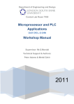
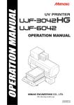
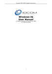
Spicer Drive Axles
®
Service Manual
Spicer® Drive Axles
AXSM-8810
January 1998
G155-T, G175-T, M190-T
M210-T, M220-T, M230-T
Two Speed Axles
TABLE OF CONTENTS
Axle Identification ................................................................ 1
Model Identification Numbering System ........................ 2
Gear Set Identification ........................................................ 2
Axle Lubricant Recommendations .................................... 3
General Precautions ............................................................. 4
Safety
Rebuild Facilities
End Yokes and Flanges
Cleanliness
Features/Power Flow Diagrams .......................................... 5
Axle Components ................................................................. 6
Removal of Differential Carrier from Axle Housing ....... 7
Disassembly
Differential Carrier ............................................... 8
Ring Gear and Support Case ............................. 9
Differential ............................................................. 10
Pinion ...................................................................... 11
Cleaning and Inspection ..................................................... 12
Assembly
Pinion ...................................................................... 13
Pinion Position ...................................................... 15
Assembly (Continued)
Pinion Setting ........................................................ 16
Differential ............................................................. 18
Ring Gear and Support Case ............................. 19
Differential Support Case Installation ............................. 20
Ring Gear and Tooth Contact Pattern ............................. 21
Sun Gear Retainer Installation........................................... 22
Installation of Carrier into Axle Housing ........................ 22
Wheel Bearing Adjustment ................................................ 23
Axle/Torque Specifications ................................................ 24
Two Speed Operating Instructions ................................... 25
Export Improvement for M230-T Model ......................... 26
Recommended Service Tools ............................................. 27
GENUINE SPICER SERVICE PARTS
cause premature component failure and may void the
warranty.
Should an axle assembly require replacement component parts, it is recommended that Spicer Heavy Axle
Service Parts be used. Spicer Heavy Axle Service Parts
are manufactured under the same rigid specification as
are original equipment axle components. This assures
the customer who uses genuine Spicer service parts,
maximum reliability for a Spicer Heavy Axle assembly.
They may be obtained through your vehicle manufacturer. The use of non-original Spicer service parts may
The items included in this book are currently being
offered as service parts at the time of printing. The
part numbers and illustrations are provided specifically
for reference purposes only. Therefore, Spicer reserves
the right to update this manual without notice or
liability.
i
AXLE IDENTIFICATION
JULIAN D
ATE CODE
DA
include customer part number, line set number, and the
last six digits of the vehicle serial number.
97 0
70
07
MODEL YEAR
The aluminum axle assembly tag contains the following
items: serial number, according to the julian date, Dana
part number, and the model. The mylar axle assembly
tag contains the following items: Dana part number,
julian date code, axle model, and ratio. Optional items
include customer part number, line set number, and the
last six digits of the vehicle serial number.
DAY OF YEAR
All axle assemblies are identified with two tags. One
located on the differential carrier, and the other located
on the right hand side of the axle housing. Two types of
tags may be found on the axle, an aluminum tag that is
riveted on the axle assembly or a coated mylar tag.
AR
T
DANA P
PAR
ART
NUMBER
The aluminum differential carrier tag contains the
following items: serial number, according to the julian
date code, the Dana part number, and ratio. The mylar
differential carrier tag contains the following: Dana part
number, julian date code, and ratio. Optional items
JULIAN D
ATE
DA
CODE
JULIAN D
ATE
DA
CODE
DANA P
AR
T
PAR
ART
NUMBER
Carrier Tag
SN 97070
MJACA000-0X
RATIO
CUS
TOMER
CUST
PAR
T NUMBER
ART
(OPTIONAL)
LAS
T SIX DIGITS OF
LAST
VEHICLE SERIAL NUMBER
(OPTIONAL)
0.00
LINE SET
NUMBER
(OPTIONAL)
Carrier Tag
DANA P
AR
T
PAR
ART
NUMBER
CUS
TOMER
CUST
T NUMBER
ART
PAR
(OPTIONAL)
MODEL
JULIAN D
ATE
DA
CODE
JULIAN D
ATE
DA
CODE
Axle Assembly Tag
LAS
T SIX DIGITS OF
LAST
VEHICLE SERIAL NUMBER
(OPTIONAL)
SN 97070
LINE SET
NUMBER
(OPTIONAL)
MODEL M190-T
MJAAB000-0
DANA P
AR
T
PAR
ART
NUMBER
1
Axle Assembly Tag
MODEL IDENTIFICATION NUMBERING SYSTEM
M 190 T N
Family
(G, M)
Gearing Type
(T = Two Speed)
Nominal Load
Carrying Capacity
(155 = 15,500 Lbs.)
(175 = 17,500 Lbs.)
(190** = 19,000 Lbs.)
(210 = 21,000 Lbs.)
(220 = 22,000 Lbs.)
(230 = 23,000 Lbs.)
Options
(N = *No-SPIN® Differential)
* No-SPIN® is a registered trademark of Tractech
** Same as 185 = 18,500 Lbs.
GEAR SET IDENTIFICATION
260
41-11
MFG.
DATE
DANA
MFG. LOCATION
HEAT
CODE
MATCHED
SET NUMBER
TOOTH
COMBINATION
PART
NUMBER
MFG.
DATE
TOOTH
COMBINATION
260
+15
41-11
HEAT
CODE
PART
NUMBER DANA
MFG. LOCATION
Manufacturer's Date- Date gear set was made.
pinion are marked with a corresponding number (i.e.
260), which identifies them as a matched set.
Spicer Trademark- Company logo and location of
manufacturing facility.
A gear set that does not have the same match set
numbers should not be run together. If either ring gear
or pinion require replacement, a new matched set must
be used.
Part number- Ring Gear (GGAGR104 TYPICAL)
Tooth Combination(i.e. 41-11)- Indicates the pinion has
11 teeth and the ring gear has 41 teeth which results in
a 3:73:1 ratio.
Matched Set Number- Spicer ring gears and pinions are
manufactured as matched sets. Both ring gear and
PINION
ETCH
Backlash Etch- Indicates backlash setting for assembly.
Pinion Etch- Indicator for proper pinion position shim
stack up. See Pinion Position Section.
2
AXLE LUBRICANT RECOMMENDATIONS
SUBMERSION OR DEEP WATER FORDING
In the event the carrier housing should become
submerged in water, particularly if over the vent plug, it
is recommended that the lubricant be drained and all
internal parts be inspected for water damage and/or
contamination. Reassemble the carrier to the housing
and refill with specified gear lubricant.
To ensure proper lubrication and operating temperature,
correct lubricants and lubricant levels must be obtained.
RECOMMENDED GEAR LUBRICANTS
Mineral or Synthetic based hypoid gear lubricants that
meet or exceed military specification MIL-L-2105D, and
API service classification GL-5, are the minimum requirements for use in Spicer Medium and Heavy Duty Drive
Axles.
AFTER OVERHAUL OR CHANGE INTERVALS
Fill the axle assembly to the bottom of housing fill hole
as shown in the illustration below. It is recommended
that following an overhaul, each side of the axle be
jacked up seperately to approximately six inches and held
into position for one minute. This procedure will allow
adequate lubricant to flow into the wheel ends and help
eliminate the possibility of premature damage to wheel
bearings and seals. Lower the vehicle to the floor and
allow ten minutes for lube to return to normal level.
Check and refill assembly to bottom of fill hole to replace
the lubricant that was directed into the wheel ends.
The table below indicates which SAE viscosities are
recommended for various temperature ranges the vehicle
will encounter.
AMBIENT AIR TEMPERATURE
SERVICE
Recommended lubricant change intervals are dependent
on the application and operating environment. The
following chart should be used to establish proper
change intervals.
APPLICATION
On Highway
NOTE: Lubricant close enough to the bottom of the fill hole to be seen or
touched is not sufficient. Lubricant must be level with the fill hole.
PETROLEUM BASED SYNTHETIC BASED**
MILES
INTERVAL
MILES
INTERVAL
100,000
1 Year
250,000
3 Year
and
50,000
On-Off Highway
1 Year
100,000
1 Year
PATENTED, PRESSURIZED LUBRICATION SYSTEM
The lube system for our two-speed axle line is unique in
the industry. It's closed and pressurized so that oil
constantly flows to critical components. The tapered
roller bearings act as a pump which provides pressurized
lube through the internal channels in the carrier to the
differential bearings, planetary gears, and differential
gears.
* Severe Service
*Severe service includes any applications operating at or near maximum
GVW or GCW ratings. This includes normally wet or dusty environment,
or consistent high load and low speed applications.
**Includes Semi-Synthetic blends that meet MIL-L-2105D specifications.
3
GENERAL PRECAUTIONS
IMPORTANT
READ THIS SECTION BEFORE STARTING
ANY SERVICE PROCEDURES
REBUILD FACILITIES
A suitable holding fixture or carrier overhaul stand is
desireable, but not necessary to rebuild these units.
Alternatley, a sturdy shop table of approximately 30
inches in height can be used with suitable means to hold
the carrier securely for rebuild operations. A light chain
hoist should be used to relocate the carrier housing and
to install or remove the ring gear and support case
assembly.
Safety glasses should be worn
at all times when assembling
or disassembling axles.
SAFETY PRECAUTIONS
Proper service and repair of vehicle components is
important to the safe and reliable operation of all motor
vehicles. This applies particularly to driving axles such
as the ones described in this manual. The procedures
recommended and described in this manual are tested,
effective methods for performing service operations.
Follow each procedure closely, making use of both the
text and illustrations. Some of these service procedures
show the use of certain tools designed specifically for
the operation being performed. They are shown as a
preferred means of performing the operation. It is not
practical to anticipate and advise the service trade of all
possible alternative methods, and of all possible hazardous consequences that could occur.
END YOKES AND FLANGES
CAUTION: Hammering on end yokes can close
in the bearing bores or misalign yoke lugs and result in
early failures of journal needle bearings or other
driveline components. Serious damage can also be
done internally to the ring and pinion set or pinion
bearings by hammering on external parts. End yokes or
companion flanges should be removed or installed using
the recommended methods outlined in this manual.
CLEANLINESS
Axle components should be steam cleaned prior to
removal from the vehicle. Dirt is abrasive and will cause
premature wear of otherwise serviceable parts.
Service personnel should use a wash tank for thorough
cleaning of parts just prior to reassembly.
Accordingly, anyone who uses a service procedure or
tool different than shown must insure that their safety,
and the vehicle's safety, will not be jeopardized by the
service method selected.
CAUTION
BRAKE LININGS CONTAIN NON-ASBESTOS FIBERS
BREATHING BRAKE DUST MAY BE HAZARDOUS TO YOUR HEALTH AND
MAY CAUSE SERIOUS RESPIRATORY OR OTHER BODILY HARM.
AVOID CREATING DUST
DO NOT REMOVE BRAKE DRUM WITHOUT PROPER PROTECTIVE EQUIPMENT.
DO NOT WORK ON LININGS WITHOUT PROPER PROTECTIVE EQUIPMENT.
DO NOT REPLACE LININGS WITHOUT PROPER PROTECTIVE EQUIPMENT.
DO NOT ATTEMPT TO SAND, GRIND, CHISEL, FILE, HAMMER OR ALTER BRAKE
LININGS IN ANY MANNER WITHOUT PROPER PROTECTIVE EQUIPMENT.
FOLLOW 0.S.H.A. STANDARDS FOR PROPER PROTECTIVE DEVICES TO BE USED
WHEN WORKING WITH BRAKE MATERIALS.
4
TWO SPEED AXLE FEATURES
This Spicer axle assembly consist of a full float, cold formed and welded, banjo-type housing member to which the
differential carrier assembly is bolted. The banjo housing is the vehicle load carrying member, and the differential
carrier assembly is the torque transmitting portion of the axle. It consist of a primary hypoid gear set for high range
operation, and a secondary planetary type spur gear set, which is combined with the primary gear set, for low range
operation. Range changes are easily made by means of a hand control button mounted on the gear shift lever (See
Two-Speed Operating Instructions, Pg. 25) The control button causes the planetary sun gear to act as a sliding
clutch member, and moves it in and out of engagement with two clutching plates to complete range changes.
POWER FLOW DIAGRAMS
HIGH RANGE
In high range, the sun gear locks the planet gears with
the planet plate and the ring gear. The unit then
functions as a single reduction axle. Power flows in the
pinion to the ring gear through the differential case to
the differential cross shaft. The cross shaft transfers it
through the differential pinion mates to the left and
right differential side gears, and finally to the axle shafts.
LOW RANGE
In low range, engine power is transmitted to the hypoid
ring gear as before. It then flows to the ring gear
internal spur teeth, which transfers it to the planet gears
that are attached to the differential case. Because the
sun gear is clutched to a stationary retainer plate, it
cannot rotate and acts as a reaction member for the
planet gears. This causes the planet gears to rotate
around the sun gear, driving the differential case at a
speed slower that the ring gear, creating the additional
low range reduction ratio and further multiplying engine
torque. From this point, power flows in the same
sequence as when the axle is in high range.
5
AXLE COMPONENTS
Axle Shaft
Sun Gear
Hex Bolt
(255-275 Lb-Ft)
(298-339 N-m)
Vent Plug
Fill Plug
(35-45 Lb-Ft)
(47-61 N-m)
Temperature
Sensor Plug
(35-45 Lb-Ft)
(47-61 N-m)
Differential Bearing Cap
Sun Gear
Retainer Plate
Adjusting Ring
Differential Bearing Cup
Differential Bearing Cone
Differential Thrust Plate
Ring Gear
Ring Gear Bolt
(See Torque Specifications)
Magnetic Drain Plug
(35-45 Lb-Ft)
(47-61 N-m)
Differential Support Case
Planet Gear Shaft
Differential Case (Planetary) Half
Planet Gear Mounting Plate
Planet Gear
Differential Bearing Cap Bolt
(See Torque Specifications)
Hex Bolt
(30-40 Lb-Ft)
(41-54 N-m)
Differential Cross Shaft
Differential Bearing Cap Washer
Differential Case Cap Half
Differential Case Bolt
(See Torque Specifications)
Differential Gear Thrust Washer
Differential Pinion Mate
Washer
Adjusting Ring
Retainer
Differential Pinion Mate Thrust Washer
Shift Fork Assembly
Differential
Support Case
Pinion
Shift Fork Shaft
Set Screw
Pinion Pilot Bearing Cap Bolt
(See Torque Specifications)
Shift Housing Seal
Pinion Pilot Bearing Cap
®
Optional No-SPIN
Pinion Oil Slinger
Pinion Pilot Bearing
Oil Slinger Seal
Inner Pinion Bearing Cone
Inner Pinion Bearing Cup
Pinion Bearing Spacer (Selective)
Stud
Washer
Nut
Carrier Housing
Carrier Mounting Bolt
(See Torque Specifications)
Outer Pinion Bearing Cup
Outer Pinion Bearing Cone
Pinion Oil Seal
End Yoke Assembly
6
Flanged Hex Nut
(700-900 Lb-Ft)
(949-1,220 N-m)
REMOVAL OF DIFFERENTIAL CARRIER
FROM AXLE HOUSING
1. Shift the axle into low range. (See Two Speed
Operating Instructions, Pg. 25)
2. Remove the drain plug and drain lubricant.
3. Remove the shift unit from carrier assembly.
NOTE: Shift unit contains lube. Provide container to
catch lubricant.
NOTE: For servicing the shift unit, refer to Vehicle
Service Manual.
4. Disconnect drive shaft at rear u-joint.
Figur
iguree 1
NOTE: If ring or pinion bearings are to be removed,
break loose pinion nut at this time.
6. Support the carrier on a roller jack.
7.
5. Remove axle shaft cap screws and lock washers, or
stud nuts and cone locks. Remove axle shafts. If
gasket is assembled between the hub and shaft,
discard the old gasket and replace with a new one
at time of reassembly.
Remove the carrier-to-housing bolts.
8. Break carrier loose from housing with use of pry
bars behind carrier flange mounting face. See
Figure 1.
Removal of Carrier from Axle Housing Complete
7
DISASSEMBLY OF DIFFERENTIAL CARRIERS
Carrier Housing
Differential Bearing Cup
Differential Bearing Cap
Sun Gear
Retainer Plate
Support Case and
Differential Assembly
Sun Gear
Adjusting Ring
Differential Bearing Cap Bolt
(See Torque Specifications)
Adjusting Ring Retainer
Retainer Plate Bolt
(See Torque Specifications)
1. Place the carrier in a suitable holding fixture such as
a carrier repair stand. If ring gear and pinion are to
be reused, measure gear backlash prior to disassembly.
Hex Bolt
(30-40 Lb-Ft)
(41-54 N-m)
NOTE: Shaft will only drive out in one direction.
7.
Remove sun gear.
8. Remove four sun gear retainer bolts and sun gear
retainer plate.
2. For double reduction models, remove the two bolts
and the double reduction plate. (Proceed to step 7)
NOTE: For ease of disassembly, the ring gear bolts can
be loosened at this time.
3. For two speed models, remove the shift fork spring
and seal from the carrier housing.
9. Remove adjusting ring retainers.
10. Remove four differential bearing cap bolts.
4A. New Style:
11. Back out either adjusting ring to relieve preload.
Remove set screw and shift fork shaft. Remove shift
fork. (Proceed to step 7)
12. Remove bearing caps.
4B. Old Style:
13. Remove adjusting rings.
14. Lift the ring gear and differential sub-assembly out
of carrier. The ring gear side of the subassembly
must be tipped up for the ring gear to clear the
pinion roller bearing retainer.
Remove the shift fork shaft snap ring, using suitable
snap ring pliers. Be sure to retrieve the retaining ring
so that it will not be lost in the differential carrier.
5. Remove sealer from shift fork shaft holes.
NOTE: Use care to avoid damage to the ring gear and
pinion.
6. Remove shift fork shaft by using a drift and hammer.
Differential Disassembly Complete
8
RING GEAR AND SUPPORT CASE DISASSEMBLY
Ring Gear
Ring Gear Bolt
(See Torque Specifications)
Planetary Gears
Differential Support Case
Differential Subassembly
Differential Thrust Plate
Differential Support Case
Planetary Gear Shafts
Planetary Gear Mounting Plate
Differential Bearing Cone
Differential Gear Thrust Washer
5. Remove planetary gears and planetary gear shafts.
1. Prior to disassembly, match mark support case
halves for reassembly in the same position. See
Figure 2.
6. Turn assembly over and support on differential
subassmbly dowel pins.
CAUTION: Care must be taken to keep differential
subassembly properly positioned in support case to
prevent damage when removing ring gear.
7.
8. Lift support case form differential subassembly.
Remove thrust washer from differential subassembly.
Figur
iguree 2
2. Remove ring gear bolts. Remove differential
support case from ring gear using pry bars.
9. If either the left
or right differential support case
bearings are to
be replaced,
remove them
using a suitable
puller. See
Figure 3.
NOTE: It is recommended that whenever the ring gear
bolts are removed, they be replaced with a new set.
3. Remove aluminum differential thrust plate.
NOTE: Thrust plate may be retained in support case,
due to oil rentention. It should be removed and cleaned
before reassembly.
4. Remove planetary gear mounting plate. Use care to
avoid damage to surfaces of plate and planetary
gear shafts.
Rotate ring gear to make sure support case is seated
squarely on differential subassembly. Using a soft
hammer, tap each side of ring gear alternatley to
remove from support case half.
Figur
iguree 3
9
Ring Gear and Support Case Disassembly Complete
DIFFERENTIAL DISASSEMBLY
Differential Case Cap Half
Differential Pinion Mate
Differential Pinion Mate Thrust Washer
Differential Case Flange Half
Differential Gear Thrust Washer
Differential Cross Shaft
Differential Side Gear
Differential Case Bolt
(See Torque Specifications)
NOTE: Differential case halves are matched and marked
during the manufacturing process. No further marking
necessary. See Figure 4.
1. Remove differential case bolts and lift off right hand
case half.
2. Remove thrust washer and differential side gear.
3. Lift out cross shaft, differential pinions, and thrust
washers.
NOTE: Inspect all parts, inlcuding the matched surfaces
of the case itself. Where necessary, replace all worn
parts. If excessive wear is noticed on all parts, it is
suggested that the complete differential assembly be
replaced.
Figur
iguree 4
If any gears are to be replaced, they must be
replaced in sets. Inspect thrust washers for scoring
and excessive wear; replace if necessary.
4. Lift out differential side gear and thrust washer.
Differential Disassembly Complete
10
PINION DISASSEMBLY
Pinion Pilot Bearing Cap
Pinion Pilot Bearing
Pinion
Pinion Position Spacer (Selective)
Oil Slinger Seal
Carrier Housing
Retainer Plate Bolt
(See Torque Specifications)
Outer Pinion Bearing Cup
Inner Pinion Bearing Cone
Inner Pinion Bearing Cup
Flanged Hex Nut
(700-900 Lb-Ft)
(949-1,220 N-m)
Pinion Bearing Spacer (Selective)
Washer
Carrier Mounting Bolt
(See Torque Specifications)
Outer Pinion Bearing Cone
Pinion Oil Seal
End Yoke Assembly
1. Turn the carrier to a vertical position and remove
the four pilot bearing cap bolts. Lift the pilot
bearing cap from the roller bearing and carrier
housing, tapping with soft hammer from underneath
side if necessary.
6. Remove pinion.
7.
2. Turn the nose of the carrier to a horizontal position
to remove the flanged hex nut. Hold the end yoke
stationary, and remove the flanged hex nut and
washer.
Near the spline end of the pinion and between the
pinion bearings is a (selective) pinion bearing
spacer used for pinion bearing preload. Retain this
spacer for possible use in reassembly.
8. Remove pinion pilot bearing from end of pinion.
9. Remove inner bearing cone from pinion.
10. Remove the pinion oil seal. Discard the seal and
replace it with a new one at time reassembly.
Remove the outer pinion bearing cone.
11. Rotate carrier to pinion nose down position.
Remove the pinion oil slinger seal from the carrier
and discard. Install a new seal at the time of
reassembly.
12. With nose of the carrier down, remove the outer
pinion bearing cup.
Figur
iguree 5
3. Remove the end yoke using a suitable puller. See
Figure 5.
13. Turn the carrier over and remove the inner bearing
cup.
4. Replace flanged hex nut (finger tight). Tap pinion
free of bearing with soft hammer.
CAUTION: Do not nick the carrier bearing bore.
5. Supporting pinion from inside carrier, remove
flanged hex nut.
Pinion Disassembly Complete
11
CLEANING AND INSPECTION
CLEANING
GEARS
1 . Parts should be cleaned with emulsion cleaners or petroleum base cleaning solvent.
NOTE: Alkaline type solutions may cause
damage to machined surfaces and should be
avoided.
2 . Make sure interior of axle housing is clean prior to reassembly.
3 . Clean all gasket surfaces of old material.
Inspect gears for excessive wear or damage. Replace
gears that are pitted, scored, broken, or worn.
DRYING
Use soft, clean, lintless towels or rags to dry components
after cleaning. Bearings should not be dried by spinning
with compressed air. This can damage mating surfaces
due to the lack of lubrication.
SHAFTS
After drying, parts should be coated with a light coat of
lubricant or rust inhibitor to prevent damage from
corrosion. If parts are to be stored for a prolonged
period, they should be wrapped in wax paper.
Inspect shafts for nicks or scoring.
INSPECTION
Prior to reassembly, inspect parts for signs of excessive
wear or damage. Replacement of these parts can prevent
premature failure and costly downtime.
SPLINES
Inspect all splines for excessive wear, distortion from
twisting, and cracking.
BEARINGS
Bearing surfaces should be inspected for pitting, excessive
wear, or overheating.
HOUSINGS
THRUST WASHERS
Inspect thrust washers for scoring and cracking.
Inspect housing for stripped threads and bending fatigue.
12
PINION ASSEMBLY
Pinion Pilot Bearing Cap
Pinion Pilot Bearing
Pinion
Pinion Oil Slinger (Selective)
Oil Slinger Seal
Carrier Housing
Retainer Plate Bolt
(See Torque Specifications)
Inner Pinion Bearing Cone
Inner Pinion Bearing Cup
Outer Pinion Bearing Cup
Flanged Hex Nut
(700-900 Lb-Ft)
(949-1,220 N-m)
Pinion Bearing Spacer (Selective)
Washer
Carrier Mounting Bolt
(See Torque Specifications)
Outer Pinion Bearing Cone
Pinion Oil Seal
End Yoke Assembly
5. Use a feeler gauge or shim stock to ensure bearing
cups are completly seated in bearing bores (.0015"
approx.). This is necessary for proper pinion
position. See Figure 8.
1. Assemble the proper pinion position spacer, oil
slinger seal and inner bearing cone onto the pinion.
2. Press pinion pilot bearing
on the pinion.
6. Install inner pinion oil slinger seal into the carrier
with the tabs locking into the oil channel. Make
sure the flat side of the seal is seated against the
bottom of the bearing cup bore so that the lip side
will be against the pinion oil slinger.
3. Stake pinion pilot bearing
onto pinion in six places,
using a center punch or
equivalent tool. See
illustration on right.
7.
NOTE: Make sure all carrier bores are free from all nicks,
dirt, or any other contamination.
4. Install the inner and outer bearing cups into the
carrier.
Install pinion into carrier using slow steady movement when sliding through inner bearing cup and
seal. The pinion should be restrained from end
movement by using a retaining strap. See Figure 9.
Figur
iguree 9
Figur
iguree 8
13
PINION ASSEMBLY
8. Rotate carrier to a vertical position. Place pinion
bearing spacer (selective) on pinion. Install outer
bearing cone onto pinion.
Pinion bearing spacers (selective) are available in the
following thicknesses.
Inches
.700
MM
17.780
Inches
.714
MM
18.136
.701
17.805
.715
18.161
.702
17.831
.716
18.186
.703
17.856
.717
18.212
.704
17.882
.718
18.237
.705
18.907
.719
18.263
9. Inspect end yoke seal surface for grooves caused by
seal lip. If grooves can be detected with a fingernail,
yoke should be replaced or have repair sleeve
installed.
.706
18.932
.720
18.288
.707
18.958
.721
18.313
.708
18.983
.722
18.339
.709
18.009
.723
18.364
10. Assemble end yoke, washer and old flanged hex nut
onto pinion. Torque nut to 700-900 Lb-Ft (9491,220 N-m). The old nut can be used during this
adjustment phase of the assembly, saving the new
one for final assembly.
.710
18.034
.724
18.390
.711
18.059
.725
18.415
.712
18.085
.726
18.440
.713
18.110
.727
18.466
NOTE: The reason for not assembling a new pinion oil
seal at this time is due to the possibility of having to
adjust pinion preload or pinion position. It would be
necessary to again remove the seal and, as mentioned,
whenever seals are removed, they are to be discarded
because of possible damage.
NOTE: Inspect pinion pilot bearing cap for proper
spotface and chamfer at the four bolt holes as shown in
Figure 10. If spotface and chamfer are not present,
machine as required .030 chamfer X 45º for holes and
1.25" spotface X .030
deep at four places.
11. Remove pinion retainer strap. Using an in-lb torque
wrench rotate pinion noting rolling torque. Rolling
torque of pinion should read between 20-50 in-lb
(2.3-5.7 N-m).
To increase preload, decrease thickness of preload
spacer: to decrease preload, increase thickness of
preload spacer. Every .001" (.025 mm) change in
thickness of preload spacer changes torque to
rotate by approximately 30 in-lb.
14. Rotate carrier to
vertical position
with yoke down.
Install pinion pilot
bearing cap using
soft hammer if
necessary.
NOTE: A pinion bearing spacer (selective) is used to
develop pinion bearing preload. See list in next column
for available thicknesses. Measure the spacer with a
micrometer before assembly to insure correct thickness.
Chamfer
.030 x 45º
15. Install four retainer
bolts. Torque to:
12. Remove flanged hex nut, washer and end yoke.
Apply a light coat of lubricant to the lip of the seal
and assemble into housing.
G Model 70-80 LbFt (95-108 N-m)
M Model 110-125
Lb-Ft (149-169 N-m)
13. Assemble end yoke, washer, and new flanged hex
nut. Torque to 700-900 Lb-Ft (949-1,220 N-m).
Recheck torque to rotate.
.030 Deep x 1.25 Spotface
Figur
0
iguree 1
10
Pinion Assembly Complete
14
PINION POSITION
Ring gears and pinions are supplied in matched sets only.
Matching numbers on both the pinion and ring gear are
etched for verification. If a new gear set is being used,
verify the number of each pinion and ring gear before
proceeding with assembly. See Gear Set Identification,
Pg. 2.
Pinion Oil Slinger
Beginning with carriers GGA-1007032 and MJA-1007160,
a new method of setting pinion position has been
adopted. A number is etched on the machined surface
under the roller bearing retainer plate on each carrier.
This number is used in conjunction with the number
etched on each pinion to determine the proper pinion
bearing spacer (selective) for proper assembly. It
eliminates the need for measuring with special gauge
tools. See Figure 7.
Nominal
Mounting Distance
Centerline
of Ring Gear
A plus (+) number etched on the pinion would mean
that number must be added to the nominal mounting
distance to get the required mounting distance.
EXAMPLE:
If pinion is etched +3, the required mounting
distance is more than nominal by .003 in. (.076
mm). This means the pinion would require .003 in.
(.076 mm) thinner shim between pinion and oil
slinger seal than a pinion etched with "0" to allow
for this difference. To achieve proper pinion
position, decrease the pinion position spacer
thickness by .003 in. (.076 mm).
Figur
iguree 7
Pinion position is based on the mounting distance
measured from the centerline of the ring gear to the
back of the pinion head (See Illustration, top of next
column). This dimension is controlled by shimming
between the oil slinger seal and pinion head with a
pinion position spacer (selective).
Similarily, if the pinion is marked -3, the shim
required between pinion and oil slinger seal would
be .003 in (.076 mm) thicker than if pinion was
etched "0" to allow for this distance. To acheive
proper pinion position, increase the pinion position
spacer thickness by .003 in. (.076 mm).
On the nose of each pinion either a plus (+), minus (-),
or a zero (0) will be etched. See Gear Set Identification,
Pg. 2. This number represents the amount in thousandths of an inch (.001) to be added or subtracted
from the nominal mounting dimension for the best
running position for that particular gear set.
The number etched on the carrier also refers to the
mounting distance, based on a "0" etched pinion.
This number represents thicness in thousandths of
the pinion position spacer (selective) required for a
"0" etched pinion.
15
PINION POSITION
The following examples illustrate how the carrier etch
and the pinion etch interact:
EXAMPLE "A"
EXAMPLE "B"
Number etched on
nose of pinion
+3
-2
Number etched on
carrier
63
61
Add or subtract pinion
etch from carrier etch
to get correct pinon
postion spacer.
Pinion position spacers (selective) are available in
the following thicknesses.
Inches
MM
.052
1.321
.055
1.397
.058
1.473
.061
1.549
.064
1.626
.063
-.003
.061
+.002
.067
1.702
.070
1.778
.060
.063
.073
1.854
.076
1.930
.079
2.007
.082
2.083
Select a pinion postion spacer that is closest to the
calculated value from table.
NOTE: The pinion position spacer functions as a
selective shim to determine the position of the pinion
mounting distance.
NOTE: Measure the new pinion position spacer with a
micrometer before assembly to insure correct thickness.
Be sure mounting surfaces and shims are free of dirt and
nicks prior to assembly or leaks will occur and pinion
position can be affected.
PINION SETTING
When a new gear set is being installed, use a micrometer
to measure the thickness of the old pinion position
shims. Measure each shim separately and add together
to get the total thickness of the original build-up.
If either or both the pinions are etched beyond the
values on this chart, follow the same procedure to
establish correct pinion position.
For example if the old pinion is etched –12 and the new
pinion is etched +9, add .021 inch to the thickness of
the original shims.
NOTE: If old shims are bent or mutilated they should be
replaced.
If a new gear set is being used, notice the (+), (–) or
"0" etching on both the old and the new pinions, and
adjust the thickness of the shims to compensate for the
difference of these two figures (as shown in table on
next page).
After determining the new total build up of pinion
position shims, round the figure off to the nearest
multiple of .005 inch.
Use the Pinion Setting Chart on the next page as a
guideline to set the pinion.
For example, if the old pinion is etched +2, and the new
pinion is –2, subtract .004 in. from the thickness of the
original shims used to position the pinion.
16
PINION SETTING
17
DIFFERENTIAL ASSEMBLY
Differential Case (Planetary) Half
Differential Pinion Mate
Differential Pinion Mate Thrust Washer
Differential Case Cap Half
Differential Gear Thrust Washer
Differential Cross Shaft
Differential Side Gear
Differential Case Bolt
(See Torque Specifications)
1. Apply a small amount of lubricant to all mating
surfaces. This will keep the thrust washers in place
during assembly, and provide for initial lubrication.
2. Place thrust washer and differential side gear in
differential case (planetary) half.
3. Assemble differential components and place into
differential case (planetary) half.
4. Place side gear and thrust washer in position on
differential pinion mates.
5. Position differential case cap half onto above
assembly, making sure match marks line up. See
Figure 6.
Figur
iguree 6
4. Install differential case bolts (M230-T export model
has 12 bolts). Tighten alternately and evenly.
Torque bolts to:
G Model: 70-80 Lb-Ft (95-108 N-m)
M Model: 110-125 Lb-Ft (149-169 N-m)
Differential Assembly Complete
18
RING GEAR AND SUPPORT CASE ASSEMBLY
Ring Gear
Ring Gear Bolt
(See Torque Specifications)
Planetary Gears
Differential Support Case
Differential Subassembly
Differential Thrust Plate
Differential Support Case
Planetary Gear Shafts
Planetary Gear Mounting Plate
Differential Bearing Cone
Differential Gear Thrust Washer
1. Install differential bearing cones onto hub of
support cases.
fered teeth facing the planet gears. Tap the plate
with a soft hammer, if necessary, to seat the plate
against the differential subassembly.
NOTE: To protect bearings during the following steps.
install bearing cups on bearing cones.
NOTE: Be sure that the planetary gear shafts and dowel
pins are flush to below flush prior to installing thrust
plate.
2. Apply lubricant to thrust washer surface and install
in differential support case.
7.
3. Install differential assembly into differential support
case. Rotate differential assembly to assure proper
installation.
Apply lubricant to each side of the differential
thrust plate and position the thrust plate on the
planetary gear mounting plate.
8. Place the support case on the ring gear and line up
the bolt holes. If old ring gear is used make sure
match marks are aligned.
4. Install ring gear on differential support case,
aligning bolt holes. Make sure ring gear is seated.
NOTE: If old ring gear is used, make sure match marks
are aligned.
NOTE: See Pg. 26 for M230-T export model assembly
instructions of ring gear bolts and retainers.
5. Lubricate and install the four planetary gear shafts
in the holes of the differential subassembly. Place
the planetary gears in position on the planetary
gear shafts.
9. Install and tighten the ring gear bolts alternately
and evenly. Torque bolts to:
G Model 110-125 Lb-Ft (149-169 N-m)
NOTE: Remove any burrs from planet gear mounting
plate.
M Model 160-180 Lb-Ft (217-244 N-m)
Ring Gear and Support Case Assembly Complete
6. Position the planetary gear mounting plate on the
planetary gear shafts and dowels, with the cham19
DIFFERENTIAL SUPPORT CASE INSTALLATION
Carrier Housing
Differential Bearing Cup
Differential Bearing Cap
Sun Gear
Retainer Plate
Support Case and
Differential Assembly
Sun Gear
Adjusting Ring
Differential Bearing Cap Bolt
(See Torque Specifications)
Adjusting Ring Retainer
Retainer Plate Bolt
(See Torque Specifications)
1. Install ring gear support case assembly into carrier
housing. The ring gear side of the support case
must be tipped to clear the pinion roller bearing
retainer plate. Care should be taken to avoid
damage of ring and pinion gear teeth and bearings.
Place bearing cups into position
Hex Bolt
(30-40 Lb-Ft)
(41-54 N-m)
6. Once proper backlash is established, torque bearing
cap bolts to:
G Model 220-250 Lb-Ft (298-339 N-m)
M Model 290-350 Lb-Ft (393-475 N-m)
7.
2. Assemble differential bearing caps. Install bearing
cap bolts (finger tight only). Install adjusting rings.
Install adjusting ring retainers, washers, and bolts.
Torque retainer bolts to 30-40 Lb-Ft (41-54 N-m).
NOTE: Assemble adjusting rings so that the side with two
shoulders is facing out to ensure clearance for the bearing
(Inside face has only one shoulder). See Figure 11.
3. Tighten adjusting ring on back side of ring gear
until there is zero (0) backlash between the ring
gear and pinion.
Proper Adjusting Ring Installation
4. Next, tighten adjusting ring (on the tooth side
of ring gear) until cup is seated. Continue to
tighten adjusting ring until backlash has returned to
measurement taken prior to disassembly.
Out
side FFace
ace
Outside
Adjusting Ring
5. Check ring gear and pinion backlash in four
equally spaced positions around the ring gear with
a dial indicator.
Relief for
Clear
ance
Clearance
Inside FFace
ace
NOTE: If backlash does not vary more than .003 in. and
the average backlash is between .008-.016 in. or (.20.40 mm) the setting is acceptable.
Figur
1
iguree 1
11
Ring Gear and Support Case Assembly Complete
20
RING GEAR AND PINION TOOTH CONTACT PATTERN
The procedures to the right are to be used to establish proper
gear tooth pattern after assembly of the carrier is complete.
NOTE: If matched sets are being reused,
measure and record backlash before disassembly, and reassemble to the same backlash.
This will match ring and pinion gears to the
established wear patterns. Hand rolled patterns will cover less area than the gear pattern
established by previous service.
STEP 1. Paint 1/4 ring gear with marking compound on
both the drive and coast side.
STEP 2. Rotate ring gear at least one complete revolution in
both directions while load is being applied.
CORRECT GEAR PATTERNS FOR GLEASON CUT GEARS
L I G H T LY
L OA D E D
H E A V I LY
L OA D E D
NOTE: Tooth contact pattern, on this axle model, can be moved only by adjusting backlash.
The contact pattern can be moved in the direction of heel-to-toe, and toe-to-heel; Depth of
the pattern cannot be adjusted. If an acceptable tooth contact pattern cannot be established
within limits of backlash, contact Spicer Service at 1-800-666-8688.
21
SUN GEAR RETAINER INSTALLATION
NOTE: See M230-T export model assembly instructions
of Sun Gear Retainer, Pg. 27.
Seal
.1
25"
.12
8 mm)
(3.18
(3.1
1. Install sun gear retainer plate with chamfered teeth
facing out and four bolts. For double reduction
models: Install the two bottom bolts only. Torque
bolts to 220-250 Lb-Ft (298-339 N-m).
NOTE: If lock plates will not fit correctly over bolts and
retainer plate, tighten the bolt until lock plate can be
installed.
Spring
2. Install sun gear. For double reduction models: Install
the double reduction plate, install two bolts and
torque to 220-250 Lb-Ft (298-339 N-m).
Figur
2
iguree 1
12
4. Insert and tighten set screw 30-40 Lb-Ft
(41-54 N-m).
3. For two speed models, slide shift fork into carrier
housing and position on sun gear. Install shift fork
shaft through hole in carrier housing and shift fork.
5. Install shift fork seal and spring. See Figure 12.
Sun Gear Retainer Installation Complete
INSTALLATION OF CARRIER INTO AXLE HOUSING
1. Thoroughly clean the inside of the carrier housing
and inspect the housing mounting surface for nicks
and general cleanliness. Stone the surface if
necessary to remove burrs or nicks.
4. Install the carrier assembly into the axle housing.
Clean the mounting bolts, and coat with Loctite
#277 (red), or its equivalent, and install. Tighten
bolts evenly in cross pattern. See torque specifications for carrier mounting bolts.
2. Apply an 1/8" bead of Loctite #518 gasket eliminator onto the axle housing mounting flange and
around each bolt hole. See Figure 13.
5. Allow one hour cure time for gasket material before
adding hypoid gear lubricant.
6. Remove the old axle flange gasket and clean mating
surfaces of the hub and axle flange.
7.
Install the new axle flange gasket.
8. Install the axle shafts to proper location. Torque
the axle flange nuts to vehicle manufacturers
specifications.
9. Clean drain plug and
install. Fill unit to
proper level with
hypoid gear lubricant.
Loc
tit
18
Loctit
titee #5
#51
sk
Gask
skeet Elimina
Eliminattor
Ga
Figur
3
iguree 1
13
3. Thread 2 studs into the axle housing 1800 apart.
This will eliminate rotation of the carrier assembly
after it makes contact with the gasket material.
NOTE : Lubricant close enough to bottom of fill hole to be seen or
touched is not sufficient. Lubricant must be level with the fill hole.
Installation of Carrier Complete
22
,
,
,,
,,,
,,
,
,
WHEEL BEARING ADJUSTMENT
NOTE: Wheel bearings should be adjusted following
vehicle manufacturers recommended maintenance
schedule.
1. Block wheels not being adjusted to insure that
vehicle will not roll. Release emergency brake.
2. Raise wheel to be adjusted off of the ground. Make
certain wheel rotates freely.
3. Remove axle shaft.
4. Remove outer adjusting nut and lock if tabs are
broken.
5. Torque inner wheel nut to 50 Lb-Ft (68 N-m) while
rotating wheel one direction, then the other direction. Back off inner nut 1/4 turn.
NOTE: When replacing wheel bearings, new bearings
must be re-seated to insure maximum service reliability.
After the hub and bearings are assembled in place on
the spindile, install the inner adjusting nut. Tighten the
inner adjusting nut to 120 - 140 Lb-Ft (163-190 N-m),
while rotating the hub to seat the bearings. Back off the
adjusting nut 1/2 turn and follow the proedure outlined
in step #5.
LUBRICANT LEVEL
6. Install lock against inner wheel nut, with locking
portion positioned on either the flat side of inner
nut or peak of inner nut, as shown.
7.
Install outer wheel nut and torque to 250-275 Lb-Ft
(340-373 N-m). Rotate wheel in both directions.
Wheel must rotate freely, with out binding.
8. Bend one tang of lock over flat portion of outer
wheel to secure.
9. Remove old axle flange gasket and clean mating surfaces of hub and axle flange.
10. Install new axle flange gasket.
11. Install axle shaft. Torque axle nuts to vehicle
manufacturers specifications.
Wheel Bearing Adjustment Complete
23
AXLE/TORQUE SPECIFICATIONS
Axle Specifications
It
em
Item
Pinion Bearing Preload*
Torque Wrench
Differential
Ring Gear to Pinion Backlash
Lubrication
Lube Capacity (Approx.**)
Lube Capacity (Approx.**)
Model
U.S.
Me
tric
Metric
G, M
20 - 50 Lb-in
2.3 - 5.7 N-m
G, M
.008" - .016"
.20 - .41 mm
G
M
25.0 pints
35.0 pints
11.8 liters
16.6 liters
* Pinion bearing preload is established prior to installation of pinion seal.
** Capacity will vary depending on the housing angle in each vehicle. Fill to lower edge of fill hole in rear of axle housing as shown on Page 22.
Fasteners
Position
Model
Thr
ead
Thread
Flanged Hex Nut
Fill & Magnetic Drain Plugs
Adjusting Ring Retainer Bolts
Differential Case Bolts
Gr
ade
Grade
Lb-Ft
G, M
1-1/4" - 12
700 - 900
G, M
3/4" - 14
8
35 - 45
G, M
3/8" - 16
8
30 - 40
G
7/16" - 14
8
115 - 135
M
1/2" - 13
8
70 - 80
Carrier Mounting Bolts
G
1/2" - 13
8
100 - 120
M
5/8" - 11
8
240 - 260
Ring Gear Bolts
G
1/2" - 13
8
110 - 125
M
9/16" - 12
8
160 - 180
Differential Bearing Cap Bolts
G
5/8" - 18
8
220 - 250
M
3/4" - 16
8
290 - 350
Pinion Pilot Bearing Retainer Bolt
G
7/16" - 14
8
70 - 80
M
1/2" - 13
8
110 - 125
Sun Gear Retainer Bolt@
G, M
5/8" - 18
8
255 - 275
@
On models equipped with Sun Gear Lock Plate (See Page 27), Retainer Bolt Torque is 220 - 250 Lb-Ft (298 - 339 N-m).
24
N-m
949 - 1,220
47 - 61
41 - 54
156 - 183
95 - 108
136 - 163
325 - 352
149 - 169
217 - 244
298 - 339
393 - 475
95 - 108
149 - 169
345 - 373
TWO SPEED OPERATING INSTRUCTIONS
The Spicer two-speed rear axle may be specified in combination with four and five speed manual transmissions.
There are 8-10 possible gear selections. The axle can be spit shifted or shifted to high when road speed is achieved.
By studying Figure 14 and using the following shift sequences, you can refine and make using the Spicer two-speed
axle an automatic occurance.
LOW TO HIGH SHIFTING
With accelerator down, move the axle selector
switch to HI.
"HI" R
ANGE
RANGE
Release accelerator.
When shift is complete, depress accelerator.
HIGH TO LOW SHIFTING
With accelerator down, move the axle selector
switch to LO.
"L
O" R
ANGE
"LO"
RANGE
Rapidly release and depress accelerator.
When shift is complete, depress accelerator.
SPLIT SHIFTING THE TRANSMISSION AND AXLE
Upshifting
While shifting transmission up to the next
higher gear,
Figur
4
iguree 1
14
Move axle selector switch to LO before
engaging clutch.
Downshifting
With the accelerator down, move the axle selector
switch to HI (pre-select).
Shift transmission down to the next lower gear.
25
EXPORT IMPROVEMENT FOR M230-T MODEL
4. Torque the ring gear bolts to 160-180 Lb-Ft (217244 N-m).
RING GEAR BOLT RETAINER INSTALLATION
1. Follow Ring Gear and Support Case Assembly
procedures 1 thru 8.
5. Bend tabs on retainers over flats of bolts. See
Figure 17.
2. Insert ring gear bolts through ring gear bolt
retainers. See Figure 15.
CAUTION: If tabs on retainers do not align with flats on
bolts, tighten bolts to next flat that will align with tab.
Bent Tab
Ring Gear Bolt Retainer
Figur
5
iguree 1
15
3. Apply a thin layer of Loctite #277 on the
threads of the ring gear bolts and install as shown
in Figure 16.
Figur
7
iguree 1
17
NOTE: Continue assembly with Differential Support
Case Installation procedures outlined on Pg. 20.
Tabs
Ring Gear and Support Case Assembly Complete
Figur
6
iguree 1
16
26
EXPORT IMPROVEMENT FOR M230-T MODEL
SUN GEAR RETAINER INSTALLATION
1. Install sun gear retainer plate. Apply Loctite #277
to threads of bolts with a grooved head and install.
Torque bolts to 220-250 Lb-Ft (238-339 N-m).
NOTE: Figures 18, 19 for proper assembly.
2. Install sun gear lock plates over bolts.
NOTE: If lock plates will not fit correctly over bolts and
retainer plate, tighten the bolt until lock plate can be
installed.
E-clip
3. Install E-clips to grove in head of bolt.
Sun Gear
Platte
Lock Pla
4. Install sun gear.
5. Slide shift fork into carrier housing and position on
sun gear. Install shift fork shaft through hole in
carrier housing and shift fork.
Gr
oo
Groo
oovved R
Reetainer Bolt
Sun Gear
Retainer Pla
Platte
6. Insert and tighten set screw 30-40 Lb-Ft
(41-54 N-m).
7.
Install shift fork seal and spring.
NOTE: Continue assembly with Installation of Carrier
into Axle Housing procedures outlined on Pg. 22.
Figur
8
iguree 1
18
Sun Gear Retainer Installation Complete
Sun Gear
Platte
Lock Pla
Sun Gear
Retainer Pla
Platte
Se
Sett Scr
Screew
E-clip
Gr
oo
Groo
oovved R
Reetainer Bolt
Figur
9
iguree 1
19
27
RECOMMENDED SERVICE TOOLS
ORDER NUMBER
DESCRIPTION
ILLUSTRATION
DST1001
CARRIER STAND
TORQUE MULTIPLIERS
DST1002
DST1003
Maximum 1,000 ft-lbs
Maximum 2,000 ft-lbs
DST1004
DST1005
Maximum 4,000 ft-lbs
Maximum 12,000 ft-lbs
DST1006
YOKE REMOVER, BAR TYPE
DST1009
INSTALLER, DIFFERENTIAL YOKE
(11/4"-12)
28
RECOMMENDED SERVICE TOOLS
ORDER NUMBER
ILLUSTRATION
DESCRIPTION
DST1000-1
SEAL INSTALLATION TUBE HANDLE
DST1000-2
PINION SEAL INSTALLER
ALL SERVICE TOOLS AVAILABLE FROM OTC DIVISION:
Service Tools
655 Eisenhower Drive
Owatonna, MN 55060
Telephone: 1-800-533-0492
Fax Number: 1-800-578-7375
29
Aftermarket
Group
ForDana
spec‘ing
or service assistance,
call 1.800.621.8084 or visit our website at www.spicerparts.com
PO Box 321
Toledo, Ohio 43697-0321
Warehouse
Distributor:
Dana
Commercial
Vehicle1.800.621.8084
Products Group
OE Technology
Dealers: 1.877.777.5360
3939
Drive
Maumee, Ohio, USA 43537
www.spicerparts.com
www.dana.com
AXSM-8810 Printed in U.S.A.
Copyright Dana Limited, 2012.
All rights reserved. Dana Limited.