1
TAS 200 Series Adjustment Procedures
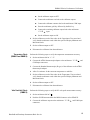
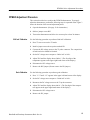
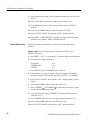
3. Set the CH 2 VERTICAL INVERT push switch to the in position and note
the new trace location.
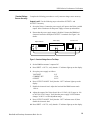
4. On the Main board, adjust VR213 to position the trace half way back to the
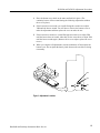
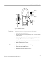
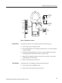
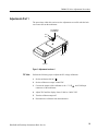
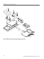
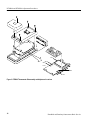
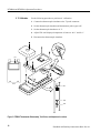
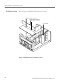
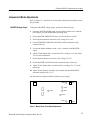
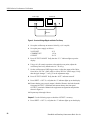
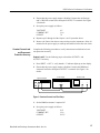
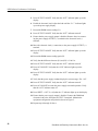
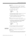
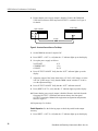
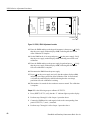
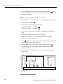
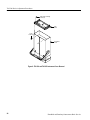
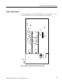
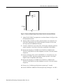
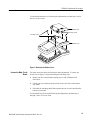
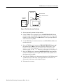
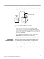
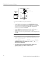
center horizontal graticule line. See Figure 8 for the adjustment location.
5. Set the channel 2 VERTICAL INVERT push switch to the out position.
6. If the trace shifts, adjust VR303 to return the trace to the center horizontal
graticule line.
7. Repeat steps 3 through 6 to obtain a minimal trace shift (<±1 division) when
you toggle the CH 2 VERTICAL INVERT push switch in and out.
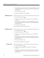
ADD Mode Balance
Use the following procedure to adjust the ADD mode balance.
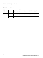
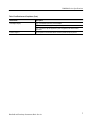
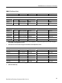
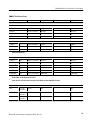
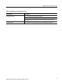
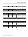
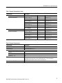
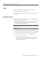
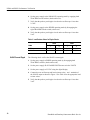
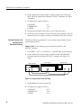
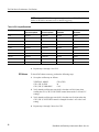
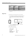
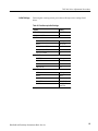
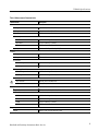
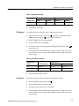
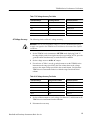
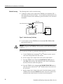
1. Set up the oscilloscope as follows:
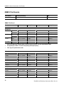
VERTICAL MODE
CH 1 (CH 2) VOLTS/DIV
CH 1 (CH 2) VARIABLE
CH 1 (CH 2) GND
BOTH
10 mV
CAL
In
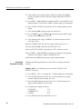
2. Position both traces on the center horizontal graticule line using the CH 1
and CH 2 VERTICAL POSITION controls.
3. Set the VERTICAL MODE control to the ADD position.
4. On the Main board, adjust VR301 to position the trace on the center
horizontal graticule line. See Figure 8 for the adjustment location.
5. Set the VERTICAL MODE switch to BOTH, CH2, and then CH1; verify
that the trace shifts less than ±1 division from the center of the display. If
necessary, repeat steps 2 through 4 to obtain the best performance.
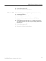
Vertical Gain
Use the following procedure to adjust the vertical gain.
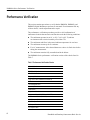
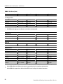
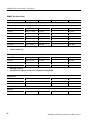
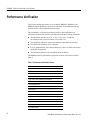
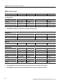
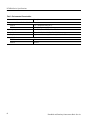
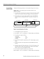
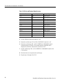
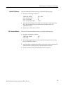
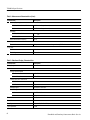
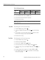
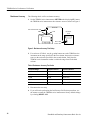
1. Set up the oscilloscope as follows:
VERTICAL MODE
CH 1 (CH 2) VOLTS/DIV
CH 1 (CH 2) VARIABLE
CH 1 (CH 2) AC-DC
CH1
10 mV
CAL
DC
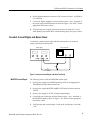
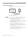
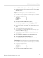
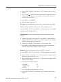
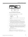
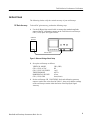
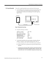
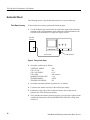
2. Connect a 50 mVp-p 50 kHz square wave to the CH 1 and CH 2 inputs with a
dual input coupler.
3. On the Main board, adjust VR108 to obtain a waveform five divisions in
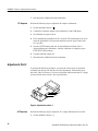
amplitude. See Figure 8 for the adjustment location.
Handheld and Benchtop Instruments Basic Service
31