1
""
Yaskawa's fully electric industrial
robot .system consists of an industrial
robot (Motoman-K6S/KlOS) , a numerical control unit (Y ASNAC ERC) , an
operating station, a wo~kpiece
mounting fixture and another equipment.
I
This manual is intended
to give operating
instructions
and
maintenance procedures primarily
for the Motoman-K6S/KlOS robot.
For
the numerical control urit,
refer to the maintenance manual for y ASNAC
ERC.
Instructions
for i the operating fixture and the another equipment
are not described in th~s manual, since they a're not furnished by Yaskawa
Refer to each supplier of those devices for instructions.
Read thoroughly
this manual prior to maintenance and retain this for further reference.
CONTENTS
1.
BASIC
BASIC
SPECIFICATIONS
.3
PARTS
NAM~ ANp WORKING
AXES
Motoman-K6S/KlO,~
DIMENSIONS
AND
"'IORKING
RANGE
OF B-AXIS
7
ALTERABLE
WORkING
RANGE
7
1.1
1.2
1.3
1.4
1.5
2.
ALLOWABLE
LOAD
ALLO"IABLE
ATTACHMENT
2.1
2.2
8
3.
ALLOWABLE
4.
HANDLING
s.
SHIPPING
6.
INSTALLATION
7.
".'iotoman
7.1
7.2
8.
MAI
3
SPECIFICATIONs
Folk
V/RIST
4
WORKING
PRECAUTIONS
LOA~
FOR '!'11RIST
8
MdUNTING
PRECAUTIONS
LOAD
9.
8
9
10
oNlu-Axls
12
BOLTS
13
ANOIJIC-'S
14
16
CO"!STRUCTld)N
POSITIO1"IS OF LI~1IT SWITCHES
Il'~TERNAL CONNBcTIONS
17
~~TENANCE
AND
FOR AXES
RECO~.1~.~ENDED
SPARE
I PARTS
16
20
Ad>JUST~~EI\jT
8.1
INSPECTION
SCHtDULE
20
8.2
INSPECTION
ITEMs
21
8.2.1 Replacement Progedures
for Battery
Unit
8.2.2 Grease Replacem,nt
Procedures
for S-, LReduction
f\lotor
24
8.2.3 Note for Wrist U~it Maintenance
25
8
RANGE
26
2 -
23
and U-axis
.s
This page is intentionally left blank!
Denna sida har med mening lämnats blank!
1
1.1
BASIC
SPECIFICATIONS
BASIC SPECIFICATIONS
Table
1.1
Basic
Specifications
Mode!
Mode
Degree
Free.dom
of
.
K1OS
Motoman-K6S
Item
Operating
of K6S and
VerticalIy
l\1otoman-K
articuIated
6
6
Payload
Verticallv
1 OS
articulated
6
.
kg
-
Repeatitive
Positioning
Accuracy
s
tO.l
axis
mm
3400
3400
2400
2400
2700
275°
3600
3600
2700
2700
4000
4000
(turning)
L
axis
(lower
u
axis
(upper
Motion
arm)
arm)
Range
R
axis
(wrist
roll)
13 axis
(wrist
pitch/yaw)
120°15
110°/5
.90°/s
110°/5
Maximum
Speed
240°/5
240°/s
400°/s
Allowable
Allowable
GD2..
Moment
Inertia
1.2
kg.m
1.0
kg.m-
0:6
kg.~
0.91
kg.~
0.67
kg.m2
0.24
kg.m2
180
Weight
MunselI
°
Temperature
7.5R3/12
to
20 to
( non-con
Humidity
Vibration
Ambient
kg
Less
Conditions
45°C
80%RH
densin
than
g)
O.5G
Free from corrosive
or explosive
gascs
.Clean
Others
Free
gases
or liquids,
all1d dry
from
excessive
electrical
noise
(plasma)
Power Capaci ty
5 kVJI.
-3
-
8 kVA
1.2
PARTS
NAME
AND
WORKING
UPPER (U)
AXES
ARM
WRIST
~
~!
03
1!;!::=1
I:rr;"fij
03
~
FLANGE
ROTARY (S)
HEAD
~
LOWER ARM
~
I' =l
/*-=
,
~
BASE
CONNECTOR BASE
Fig.
1.1
Parts
Name and \AJorking Axes
4
1.3
Motoman-K6S/KlOS
DIMENSIONS
AND
WORKING
RANGE
Motoman-K6S
Dimensions
VIEW
@
:
<
~
<
~
16
~
f-+-
J
~
~
<
~
§
3 ~
<:;'009
:'1 :;(
VIE\-l
@
:
Baseplate
Fig.
1.2
and
l\1otoman-K6S
Oimensions
Working
Range
5
"'rist
Flange
in mm
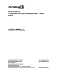
1.4
WORKING
RANGE
OF B-AXIS
B-axis moves in the range maintainirig
U-axis, as shown in Fig. 1.4.
, constant
I
angle to the center of
~.
."'
Fig.
1.5
ALTERABLE
, .4
WORKING
\"Jorking
R~nge of B-axis
RANGE
The working
range of S-axis can be al l ered
conditions
shown
Yaskawa
as
representative
in
Table
in
1.2.
If
al
eration
according
to
is necessary,
advance.
Table
1 J2
Item
Specifications
:t 17
o
(Standard)
:t150o
S-axis
Working
:t120o
Range
:t90o
:t60o
:t30o
7
the
operating
contact
your
2.
2.1
ALLOWABLE
LOAD
ALLOWABLE
FOR
WRIST
AND
PRECAUTIOf'IS
LOAD FOR WRIST
(1) The allowable load for wrist of Motoman-K6S and -KIOS is 6 kg and
10 kg, respectively,
including the weight of the grip.
The following
conditions should be observed.
(2) If force is applied to the wrist instead of the load, force on R-, Band T-axis should be within the values shown in Table 2.1.
Contact
your Yaskawa representative for further information or assistance.
(3)
Where
the
Fig.
2.1.
volume
of
load
is
small,
refer
to
limit
load
Lb(mm)
(a)
gravity
Lb(mm)
(b)
Motoman-K6S
Fig.
2.1
Limit
-8
Load Gravity
-
Motoman-K1OS
shown
in
.Inside
fitting :
The fitting
.Gutside
depth must be 5 mm or less .
fitting :
If th'e outside fitting
is used,
the fitting
depth must be 5 mm or less.
=:>
Wrist
Q
Flange
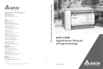
3. ALLOWABLE
LOAD ON U-AXIS
When peripheral equipment is attached
conditians should be observed.
(1)
to thi~ U-axis,
the following
Motoman-K6S
.A1lowable
load
.Unbalance
3 kg:m
(at
on
U-axis
moment
at
Wl=3
kg)
:
the
lS kg max
center
of
U-axis;
rotation
:
.Never
perform additional modifications on the robot to make provisions for other conditions.
For attaching the equipment on U-axis
use clamps shown in Fig. 3. 1.
4-}16x PI,
28
j5
12
t
t5
~
t
(kg),
15 ""'
~
'-'
,
~
N
Rr
WI
=
LOAD
CAPACITY
(kg)
10
E-o
:I:
C
H
t.J
~
'When load capacity WI
equals 10 kg, un1;~lanced
nment is not permitted.
--
100200
300400 \mn)
200100
I
DISTANCE
POINT
I
BETWEEN
U
AND
LOAD
GRAVITY
"'
~
w,'
...w,
U-AXIS ROTATION
CENTER (POINT U)
(
1
J
~
Fig.
3.1
Allov.Jable
Dimensions in mm
Load on U-axis
-10
-
for
~.1otoman-K6S
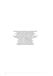
3.
(2)
ALLOWABLE
LOAD
0"'1 U-AXIS
(Cont'd)
~1otoman-KlOS
.A11owable load on U-axis:
25 kg max.
.Unbalance moment at the center of U-axis rotation:
6 kg:m (at WI=5 kg)
.Never perform addition al modifications on the robot to make provisions for other conditions.
For attaching the equipment on U-axis,
use clamps shown in Fig. 3.2.
4-M6 x12PI,.
-.§&.-- 45
-.,
-. I
~
~
~
81
L
(kg)
"
:1=
-
W1
~
25
WI
20
E-:I:
c
H
t.J
:1=
15
5
-Wll~
~
"
10
200 100
=
LOAD
GRAVITY
('kg)
I
*When load capacity W1
equals 10 kg, UnbalancErl
m:xrent is not pennitteCI.
100200 300 400 (mm)
DI S TANCE
BETWEEN
POINT
U AND LOAD
w.
GRAVITY
$:1
-fV!
+w,
U-AXIS
ROTATION
CENTER
(POINT
U)
..o:
-ILL..L
Q
Dimensions in mm
~
Fig.
3.2
Allowable
Load on U-axis
11
for
Motoman-K10S
5.
SHIPPING
BOL TS
AND
JIGS
Motoman is provided with shipping bolts and ji!~s at @ to @ in Fig. 5.1
to protect the robot from the movement and forces during shipment.
The
jigs are painted yellow.
Be sure to remove thE~mbefore .insta11ation.
NOTE
Before
turning
ori the power,
check
to be
shipping
bolts
and jigs have been removed.
so may cause ciamage to the driving
parts.
sure that
the
Failure
to do
These shipping bolts and jigs must be stored for future
event of moving or carrying the robot.
-~
~~
~
Fig.
5.1
Positions
of Shipping
-13
E3olts and Jigs
use in the
6.
INSTALLATION
The Motoman should be firmly mounted on a baseplate, or foundation rigid
enough to support the Motoman and withstand repulsion forces during
acceleration and deceleration.
Mount the baseplate in either of the
following ways.
For mounting dimensions of Motoman baseplate, see par.
1.3.
(1) Where the Motoman and the mounting fixture
flat steel plate (common base) :
are installed
on a comm9n
The common base should be rugged and durable to prevent shifting of the
Motoman or the mounting fixture.
When the Motoman is used for welding,
connect the ground lead to the Motoman baseplate.
For Motoman baseplate
SPRING
mounting,
see Fig.
WASHER
6.1
~ BOLT
WASHER
Motoman
COMMON
Fig.
(2) ~ere
6.1
Motoman Baseplate
the Motoman is mounted
directly
the concrete
thickness
(f1oor)
t,1ounting
on the floor:
The floor should be rigid enough to support
construction
procedure
are as follows .
."IThere
BASEPLATE
BASE
the
Motoman.
Foundation
is 150 mm or more
(i} The surface of floor should be level and even.
grind the swell and flatten the surface.
If it is uneven,
(n) Check for cracks on the floor.
If any c:rack is found, remove the
material around the crack and rebuild the floor with concrete.
Place the
robot by fastening the plate with M20 anchor bolts.
The plate is tapped
for M20 bolts .
Where the cancrete thickness
faundatian .
8
(flaar)
is less 1:han 150 mm ar an earth
(i) Dig a footing in the floor area.
(n) Spread stones in the excavated area and tamp them sufficiently
make a solid stone bed .
to
(~ Fi11 the empty space of the stone bed with grout, and 1ay the
concrete foundation.
It should be more than 150 mm thick, and the
surface must be leve1 and even.
(v) The concrete
the robot.
should
be ,cured
for more than
14 -
a week before
installing
6.
(3)
INSTALLATION
Mounted
types
Foot-mounted
available .
l.
(Cont'd)
wall-mounted
(Standard),
For wall-mounted
Motoman-K6S:
type,
S-axis
and c:eiling-mounted
working
range
types
are
is as follow.
!3ao
.Motoman-KlaS:
!45°
2. The brakes in S-axis and in ""rist (R-, B- and T-axis) are optional.
When using wall-mounted type, S-axis should be provided
with a brake.
8
( 4) Incorporated
cables
and air duct
1. Six cables and an air
application .
.Allowable
.Max
duct
pressure
application
are incorporated
curren t of cables:
of air duct:
(:1:>
in tl1otoman for
user
6.6 A or below
9.9 kgf/cm2
or below
CD
Incorpora1:ed
cable connector
Type M53102A 18-15 (with
cap):
Connect
the plug
type
M53106B
to this .
(i)
(J)
for
..
~~
VIEW
@
Air
O)
Incorpora1:ed cable connector
Type M53102A 18-1? (with cap) :
Connect the plug type M53106B 18-15
to this .
@)
Air
@
~
A:
~
Fig.6.2
Locations
Connectors
intet:
6.3
PT3/8
of Incorporated
and Air
Inlet
cables:
.Using
A to F
Detailed
Drawing
-15
of Connector
-
tap,
with
with
bull
bull
plug
plug
Cable
connectors
.Incorporated
pins:
tap,
PT3/8
inlet:
2. The same pin Nos. (A to F) between
O. 75 mm2 lead wires .
Fig.
18-1P
are connected
0.75
mm2,
Pin No.
6 cables
with
7.
7.1
Motoman
POSITIONS
CONSTRUCTION
OF
LIMIT
SWITCHES
FOR
AXES
Fig. 7.1
Locations of
S- and L-axis Limit Switches
16
7.2
INTERNAL
CONNECTIONS
Highly
reliable
connectors
which
can be easily
removed
connector
part.
In Figs.
7.3 and 7.4,
"-<I;:-"
shows
can also be removed.
For the numbers
and locations
Fig.
7.2.
Fig.
Locations and t~umbers of Connectors
7.2
Table
Name
are used with
each
pin connector
which
of connectors,
see
7.2
!'-!o.
List of Connector
Type
Receptacle. Ty~)e
Plug Type
I-CA3106B.
Base Connector
lFor
Incorporated
ZBC
3BC
MS3106B.36AIOS
MS3102A.18-1P
ICable
Intermediate
Connector
s~
Feedback Unit
Connector
Connector for .
Incorporated
Cable
lfiJ:tf
32P:lOS
l-.f53106B .18-15
i2p~n~-I)
172170-1
172162-1
1-480276-0
1-171196-0
172168-1
172160-1
172168-1
172160-1
MS3106B.18-P
MS3102A.18-1S
(Optional)
17 -
This page is intentionally left blank!
Denna sida har med mening lämnats blank!
This page is intentionally left blank!
Denna sida har med mening lämnats blank!
This page is intentionally left blank!
Denna sida har med mening lämnats blank!
This page is intentionally left blank!
Denna sida har med mening lämnats blank!
8.
t..1Alt-JTENANCE
8.1 INSPECTION
AND
ADJUSTt..1ENT
SCHEDULE
To insure optimum life of operation, a suggested schedule of periodicalinspections and adjustments is offered.
Adjust the schedule according to
your operating conditions.
Especially, axes frequently used for handling
should be checked at half-periods of the follo~'ing schedule .
Fig.
8.1
Inspection
-20
Schedule
-
8.2
INSPECTION
ITEMS
-E~-AXIS
(Contid)
~
-AXIS
/,.--~-~
~
R-AXIS
Fig.
8.2
Inspection
Parts
-22
and Inspection
Number
8.2.1
Replacement
If the
to the
battery
following
Procedures
for Battery
charge
becomes
procedures
.
(1)
Remove
the
side
cover
(2)
Remove
the
battery
(3)
Remove
the
pins
too
(U-axis
unit
CD.
low
or
motor
mounting
@
is
depleted,
side)
screw
(PC-2005-M,
replace
of rotary
it
head.
sides
of battery.
-E--{>
DIODO
( 4) Remove the old battery
and mount
the new battery.
NOTE
l.
2.
When the battery
unit is replaced.
Keep the power ON between y ASNAC
and Motoman .
Be sure
direction.
to insert
Fig.
the
8.3
pins
in
correct
Battery
-23
Loca1~ion
-
according
(M5) .
W) on both
~BATTERY
-E{=:J-<
oE-c:)--<
(D
(g;
f
-<
Unit
8.2.2
Grease
Replacement
Reduction
Motor
(l)
(2)
Remove
plugs
Inject
grease
using
grease
@
,
Procedures
@
and
(EPINOC
for
S-,
L-
and
U-axis
(f) .
APO)
into
grease
inlet
on
@ and @
@,
gun.
Table
Amount
8.2
of Greasing
L- and U-axis
S-axis
MotomanK6S
700 cc
300
MotomanK1OS
600 cc
400 cc
cc
(3) The grease replacement is completed when new grease appears from @
@ and @ .The
new grease is distinguished. ofrom old grease by
color.
(4) "Iipe
parts
@ ,
@
and
@
with
a cloth
and
reinstall
the
plug
.
~
(f)
@
INLET
GREASE
~
U-AXIS
REDUCTION
MOTOR
@
. 1.~
~
L-AXIS
REDUCTION
~-
MOTOR
'.
--.
~
--,--~
r-:~
7SIS
GREASE
I
Oetailed
LReduction
S-axis
t-.~otor
INLET
REDUCTION
Ioetailed
L- and u-axisl
L Reduction f\"otor PartJ
l
Par~
S-AXIS
MOTOR
@
MOTOR
n
,..,.,.-r--
;,
.1..'
I"
I"
MOTOR BASE
S-AXIS
REDUCTION
MOTOR
@-:
/Uf~
L-AXIS~\
MOTOR
~
CQVER
Fig.
8.4
Grease
~
-~
Lubricated
24 -
I ~.:J
":-7"
~/
t"""
~ U-AXIS
FLANGE
\LOWER
L-AXIS
REDUCTlON
Parts
(L)
ARM
MOTOR
.
REDUCTION
MOTOR
MOTOR
8.2.3
Note for Wrist
Unit
tJaintenance
The motor and feedback unit are provided ,:X'ith the wrist unit.
To
counteract fumes from welding operation, etc. , the hatched parts are
sea]ed with sealing compound so that fumes from welding operation, etc. do
not penetrate into the wrist unit.
Therefore" if the wrist shaft is disassembled, reseal with seaUng compound (KE4~;RTV) .
Fig.
8.5
Sealing
-25
Part of V~'rist Unit
-
9. RECOMMENDED SPARE PARTS
It is recommended that the following parts and components be kept in
stock as spare parts for the Motoman-K6S/K10S.
List of spare parts for
Motoman-K6S and KIOS is shown in Table 9.1 and 9.2, respectively.
They
are ranked A, B and C, as follows .
Rank
A:
Expendable
be expected.
parts
and
those"1or
Rank
B: Pal-ts for which replacement
frequent operation .
which
frequent
replacement
may be necessary
as a result
can
of
Rank C: Drive units
Table
Rank
Spare
Part
No.
Parts Name
1
z
9.1
Spare Parts for Motoman-K6S
Type
Manufacturer
Qty
I Oty per
Unit
H\\'8471013-A
Limit switch
set
1
1
3
A
Rema..ks
S-axis,
Lead terminal
treatment
completion
L-2xis,
Lead terminal
treatment
completion
4
S
2.5
Grease
kg
6
7
Sillcon
rubber
compound
(tube)
1
8
Gear
9
n
10
Yaska~.a
1
l
1
2
1
1
~
1
EJectric
II
12
I.Ug.
Go.,
Ltd.
Speed
reducer
13
~
14
-
1
I
15
~
16
AG
Servomotor
17
c
T-axis (Tip)
Yaska~.a
Elcctric
"Ifg.
Go. .Ltd.
18
19
ZO
Interna!
wiring
ZI
ZZ
Wrist unlt
26 -
1
1
1
1
1
2
1
3
1
1
1
1 I
1
1
1
1
Without
brake
With
brake
Without
brake
In L ann
With key.
Lead
terminal
treatmcnt
completion
~
9.
RECOM""\ENDED
SPARE
Table
Rank
Sp;)re
P;)rt
No.
Parts Nanle
9.2
PARTS
Spare
(Contid)
Parts
for
Motoman-KlOS
I.\anu(acturcr
Type
j Qty
()Cr
Unit
Qty\
1
2
Limit swltch
set
1
1
3
Rcm;)rks
I k"d
tcrminal
l treatment
S-ax Is
, completion
4
A
5
2.5
kg
Grease
6
7
Silicon
rubber
compound
(tube)
I
Shln-Etsu
Chemical
Co..
8
Gear
1
KE4SRTV
Ltd.
11\\.8~2S13S-1
H\\'8~2S133-1
1
2
9
B
1
10
2
II
14
l
l
1
15
2
1Z
13
~
brake
Ilith
l With
I L.ead
key.
terminal
treatment
, 1
16
c
3
17
1
18
1
]9
1
1
20
1
21
.8
8
-27
-
Without
brake
in L arm
completion
This page is intentionally left blank!
Denna sida har med mening lämnats blank!
TOE..c945-111
MOTOMAN
Box 504
ROBOTICS
8-38525
Torsås
AB
MAY 1994
8weden
Tel. int. 46486-10575
Fax. int 46486-11410
MOTOMAN
ROBOTICS
1 Swan Industrial Estate Banbury
Tel. int. 44295-272755
Fax. int. 44295-267127
OXON
U.K
LTD
OX16 8DJ England