1
INSTALLATION, OPERATION AND SERVICE MANUAL
COOK TANKMODEL: CT-600
CT-1000
CT-2000
CLEVELAND RANGE INC.
1333 East 179th St.
Cleveland, Ohio
U.S.A. 44110
Toll Free 1-800-338-2204
SE95024 Rev. 2
TABLE OF CONTENTS
Installation
General . . . . . . . . . . . . . . . . . . . . . . . . . . . . . . . . . . . . . . . . . . . . 1
Inspection . . . . . . . . . . . . . . . . . . . . . . . . . . . . . . . . . . . . . . . . . . . 1
Shipping Damage Instruction . . . . . . . . . . . . . . . . . . . . . . . . . . . . 1
Installation . . . . . . . . . . . . . . . . . . . . . . . . . . . . . . . . . . . . . . . . . . 1
Electrical Service Connection . . . . . . . . . . . . . . . . . . . . . . . . . . . . 1
Wire Connection . . . . . . . . . . . . . . . . . . . . . . . . . . . . . . . . . . . . . . 1
Installation Check. . . . . . . . . . . . . . . . . . . . . . . . . . . . . . . . . . . . . 1
Installation Drawing. . . . . . . . . . . . . . . . . . . . . . . . . . . . . . . . . . . 2
Operating Instructions
Operating Controls Drawing . . . . . . . . . . . . . . . . . . . . . . . . . . . . 3
Operating Instructions- Using MRC 7000 Chart Recorder . . . . . . 4
Typical Operating Sequences - Without Meat Probe . . . . . . . . . . . 5
- Meat Probe Operation . . . . . . . . . 5
Cleaning Instructions
Care & Cleaning . . . . . . . . . . . . . . . . . . . . . . . . . . . . . . . . . . . . . 6
Service Parts
Warranty. . . . . . . . . . . . . . . . . . . . . . . . . . . . . . . . . . . . . . . . . . . . 7
Control Console Components . . . . . . . . . . . . . . . . . . . . . . . . . . 7-8
Electrical Components . . . . . . . . . . . . . . . . . . . . . . . . . . . . . . . . . 9
Motor/Fan Assembly. . . . . . . . . . . . . . . . . . . . . . . . . . . . . . . . . . 10
Miscellaneous Assemblies . . . . . . . . . . . . . . . . . . . . . . . . . . . 11-12
Main Console Components . . . . . . . . . . . . . . . . . . . . . . . . . . 13-14
Spring Assist Hinge Assembly . . . . . . . . . . . . . . . . . . . . . . . . . . . 15
Maintenance
General Maintenance Instructions . . . . . . . . . . . . . . . . . . . . . . . 16
Hinge Adjustment Instructions . . . . . . . . . . . . . . . . . . . . . . . . . . 16
Switch Configuration & Disassembly . . . . . . . . . . . . . . . . . . . . . 16
Solenoid Valve Maintenance . . . . . . . . . . . . . . . . . . . . . . . . . 17-18
Motor Replacement Procedure . . . . . . . . . . . . . . . . . . . . . . . . . . 19
Programming Instructions
MRC 7000 Enable Mode Procedure . . . . . . . . . . . . . . . . . . . . . . 20
MRC 7000 General Programming Instructions . . . . . . . . . . . 21-22
Wiring Diagram
. . . . . . . . . . . . . . . . . . . . . . . . . . . . . . . . . . . . . . . . . . . . . . . . . . 23
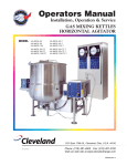
INSTALLATION
GENERAL
ELECTRICAL SERVICE
CONNECTION
Installation of the Cook Tank must be accomplished
by qualified installation personnel working to all
applicable local and national codes. Improper
installation of product could cause injury or damage.
Install in accordance with local codes and/or the
National Electric Code ANSI/NFPA No. 70-1990 (USA)
or the Canadian Electrical Code CSA standard C22.1
(Canada). A separate fused disconnect switch must be
installed and electrically grounded by the installer.
This unit is built to comply with applicable standards for
manufacturers. Included among those approval agencies
are: UL, NSF, ASME/Ntl.Bd., CSA, ETL, CE, and others.
Many local codes exist, and it is the responsibility of
the owner/installer to comply with these codes.
The electrical supply must match the power
requirements specified on the units rating plate.
The copper wiring must be adequate to carry the
required current at the rated voltage. Refer to the
specification sheet for electrical specifications.
INSPECTION
Before uncrating, visually inspect the unit for evidence
of damage during shipping. If damage is noticed, do
not unpack the unit, follow shipping damage instructions.
WIRE CONNECTION
SHIPPING DAMAGE
INSTRUCTIONS
2. Remove chart recorder.
1. Remove the four screws holding the chart
recorder in place.
3. Feed correctly sized permanent copper wire
through the hole in the back of the component
compartment.
If shipping damage to the unit is discovered or
suspected, observe the following guidelines in
preparing a shipping damage claim.
4. Connect the wire to the four connection
terminal block.
1. Write down a description of the damage or the
reason for suspecting damage as soon as it is
discovered. This will help in filling out the claim
forms later. If possible, take a polaroid picture.
5. Connect the ground wire to the ground lug.
NOTE: Insure the motor turns in the direction of
the arrow. Clockwise from fan side, or counter
clockwise from motor end.
2. As soon as damage is discovered or suspected,
notify the carrier that delivered the shipment.
3. Arrange for the carrier's representative to
examine the damage.
6. Feed the two control wires into the component
compartment and attach to the two connection
terminal block.
4. Fill out all carrier claims forms and have the
examining carrier sign and date each form. .
7. Replace chart recorder.
8. Replace side and rear panels.
INSTALLATION
INSTALLATION CHECK
1. Refer to the INSTALLATION DRAWING for the
clearance requirements, in order to determine
the location of the unit
Although the unit has been thoroughly tested in the
factory, and a factory representative will generally
perform a start up inspection. The installer is still
responsible for ensuring the proper operation of the
unit once installed. Following are a few basic
functions that can be checked easily.
2. Check the load weight of your unit and the
maximum load the floor can carry to insure the
unit can be safely positioned.
3. Remove the crating material and position the unit.
1. Supply power to the unit is correct and
separately fused. When turned on the green
light will illuminate.
4. Remove the console side and back panel.
5. Connect plumbing to unit. Labels have been
attached to each termination point. If a label is
missing refer to the specification sheet.
2. Check all plumbing connections for correct
termination.
NOTE: The plumbing leading to this unit must be
sized correctly in order to have a sufficient water
and steam supply for correct operation.
3. Check that the unit is level.
4. Check that the fan motor rotates in correct
direction.
1
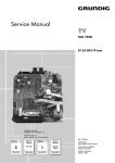
36"
I.D.
MODEL
CT-600
CT-1000
CT-2000
B
VOLUME
202 U.S. gal.
332 U.S. gal.
531 U.S. gal.
I.D.
A
79"
91"
127"
2
B
48 3/16"
60 3/16"
96 3/16"
C
37 1/8"
45 5/8"
45 5/8"
For CT 2000 only
A
4
5
6
10
5
6
10
MEAT
PROBE
MEAT
PROBE
D
29 1/2"
38"
38"
7
8
4
9
3
1
2
0
7
8
0
9
3
1
2
MAN
MAN
ON
OUT1 OUT2 ALRM
MAN
AUTO
MAN
AUTO
OUT1 OUT2 ALRM
OFF
SP
SP
DRAIN
MEAT PROBE
BY-PASS
MAN
MAN
ON
˚C
˚F
U
˚C
˚F
U
˚C
˚F
U
˚C
˚F
U
START
START
48"
F
20 7/8"
29 3/8"
29 3/8"
2"
C D
F
27"
25 1/2"
19"
10"
8 1/8"
4 5/8"
G
2 1/4"
6"
Min.
E
4"
1 1/8"
(Open Cover)
Rear of
Console
3"
Typ.
(Rear of Console)
VIEW "G"
Unions on service
connections should be
staggered for wrench
clearance during installation.
Supplied with factory installed shut-off valves.
PIPE TERMINATION
OVERFLOW DRAIN - 1 3/4" I.D. FLEXIBLE HOSE
ELECTRICAL SUPPLY: 120/208v. 14 amps.,
or 220/380v., 10amps. or 240/415v., 10amps.
1" NPT. COLD WTER IN
1" NPT. HOT WATER IN
1/2" NPT. CONDENSATE RETURN
1" NPT. STEAM IN
2" NPT. DRAIN
2" NPT. CHILLED WATER IN
2" NPT. CHILLED WATER RETURN
Legend
All connection dimensions are
from face of elbow as shown.
(except
which go straight to floor)
&
RIGHT =12"
LEFT = 0"
REAR =18"
Clearance
Lockable control panel cover not shown.
E
82 3/4"
91 1/4"
91 1/4"
6 5/8"
OUT1 OUT2 ALRM
MAN
AUTO
MAN
AUTO
OUT1 OUT2 ALRM
OFF
Cleveland
SP
SP
DRAIN
MEAT PROBE
BY-PASS
Cleveland
5 1/4"
INSTALLATION
DRAWING
OPERATING INSTRUCTIONS
14
1
0
2
Cleveland
10
1
9
2
8
MEAT
PROBE
MEAT PROBE
BY-PASS
START
OFF
3
DRAIN
ON
4
7
4
5
6
MAN
OUT1 OUT2 ALRM
SP
˚C
˚F
U
7
15
3
6
AUTO
8
MAN
5
AUTO
MAN
9
MAN
OUT1 OUT2 ALRM
SP
˚C
˚F
U
10 11
12
13
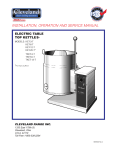
Operating Controls Drawing
ITEM #
DESCRIPTION
FUNCTION
1.
By-Pass Switch
Tells chart recorder if meat probe is functional.
2.
Power Switch
Turns power ON/OFF, turns drain ON.
3.
Start Button
Push to start the system.
4.
Meat Probe Switch
Used to set the product temperature.
5.
Water Bath Switch
Used to set the water bath temperature.
6.
Keypad
Used to program time/temperatures.
7.
Pilot Light (green)
Power indicator.
8.
Pilot Light (red)
Heating indicator.
9.
Pilot Light (blue)
Cooling indicator.
10.
MRC 7000 Chart Recorder
Time/Temperature chart recorder.
11.
Locking Arm
Holds chart paper in place.
12.
Chart Paper
Lined for time/temperature recording.
13.
Pens
Records temperature on chart paper.
14.
Timer
Set to produce desired cooking time.
15.
Meat Probe
Senses product temperature
3
MAN
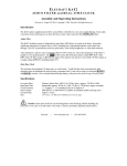
OPERATING INSTRUCTIONS
USING MRC 7000 CHART
RECORDER
Pen 1 Meat Probe
OUT1 OUT2 ALRM
SP
˚C
˚F
U
Pen1 key AUTO/MAN
Cleveland
SCROLL Key
AUTO
MAN
UP Key
MEAT
PROBE
DOWN Key
AUTO
MAN
MEAT PROBE
BY-PASS
OFF
MAN
Pen 2 key AUTO/MAN
OUT1 OUT2 ALRM
DRAIN
START
ON
SP
˚C
˚F
U
Pen 2 Water Bath
Manual
Heating Cooling
Output 1 Output 2
Alarm
0
MAN
10
9
1
OUT1 OUT2 ALRM
2
Setpoint
Indicator
SP
Minus Sign
8
3
˚C
˚F
˚U
7
4
5
6
Setting must be done in this order:
1. Set timer by rotating dial.
Note: Turn past one hour and then
set time - a minimum of 15 minutes is
required for cook tank to work correctly.
2. Turn right hand switch to "ON".
3. Set left hand switch to "MEAT PROBE" or
"MEAT PROBE BY-PASS".
4. Set temperatures on chart recorder.
MRC 7000 Controls Drawing (2 pen)
A. WATER BATH TEMPERATURE:
1. Push and release key "
".
Note: A green light will come on in the
bottom display window underneath the
S.P. (set point) symbol. This temperature
can be altered as long as this light is on.
2. Push key "
temperature.
" or "
" to set
B. MEAT PROBE TEMPERATURE:
1. Push and release key "
".
NOTE: A green light will come on in the
top display window underneath the S.P.
(set point) symbol. This temperature can
be altered as long as this light is on.
2. Push key "
temperature.
" or "
" to set
Note: Once MRC 7000 is turned on, it will remain
on even when the power switch is turned off.
Steps D and E are only necessary when the
display is alternating between "OFF " and the
temperature display.
To turn on:
D. Push function key "
displayed.
" until "CtrL" is
E. Push and release the key "
5. Push "START" button.
4
".
⇒ Circulation pump for ice water activates.
TYPICAL OPERATING
SEQUENCES
NOTE: The tank will continue in the cooling mode
until the Power Switch (2) is turned to "OFF".
NOTE: See page 3 for part number designations.
DRAINING UNIT
WITHOUT MEAT PROBE
1. Turn the Power Switch (2) to "OFF". This will
stop the cold water circulation pump and the
agitator fan. The unit will not drain.
2. Turn the Power Switch (2) to "DRAIN". The unit
will drain.
NOTE: The unit can be checked for correct
operation without product.
1. Date and label a new sheet of Chart Paper (12)
and install in MRC 7000 Chart Recorder (10).
2. Load the unit with product.
3. Set the total operating time by turning the dial
on Timer (14) clockwise.
4. Turn Power Switch (2) to "ON".
5. Turn By-Pass Switch (1) to "MEAT PROBE BYPASS".
6. Set the desired water bath temperature by
pushing the pin wheels on the Water Bath
Switches (5).
MEAT PROBE OPERATION
1. Turn dial on Timer (14) to desired soak time.
2. Turn Power Switch (2) to "ON".
NOTE: Meat probe cooking can be tested using
an apple for product.
3. Turn By-Pass Switch (1) to "MEAT PROBE".
NOTE: Soak time is the amount of time the
product wiII remain at the meat probe temperature
setting once it has been reached.
NOTE: The time you set on the timer is the total
run time including the time it takes to fill the tank.
7. Push "START" Button (3).
4. Set the meat probe temperature by pushing
the pin wheels on the Meat Probe Switches
(4).
5. Set water bath temperature by pushing the pin
wheels on the Water Bath Switches (5). This
should be 5 to 10 degrees higher than the
meat probe temperature setting.
6. Date and label a new sheet of Chart Paper (12)
and install in MRC 7000 Chart Recorder (10).
7. Insert meat probe tip through casing into
centre of product.
8. Incase this bag in a second bag. Remove as
much air as possible and tie the bag around
the probe with a tie wrap.
9. Load tank with product. Use adjustable
dividers as required in the baskets to prevent
excessive movement of product.
11. Push the Start Button (3).
RESULTS:
⇒
⇒
⇒
⇒
Green Pilot Light (7) will illuminate.
Timer (14) will start timing down.
Hot water will enter tank.
Heating system will activate and Red Pilot
Light (8) will energize.
⇒ Water level will rise and circulation fan will
activate.
⇒ Hot water will stop entering tank when water
level is within 1 to 2 inches from the top.
⇒ Water temperature will rise until it reaches the
water bath temperature setting.
⇒ Water temperature will be maintained until
RESULTS:
Timer (14) times out.
The steps the tank will go through are the same as
in the meat probe by-pass mode, with the
following exceptions.
⇒ Timer (14) times out.
⇒ Heating system is shut off. Red Pilot Light (8)
turns off.
⇒ The Timer (14) will not start timing down until
⇒ Drain opens and water drains out.
⇒ Drain closes and cold water begins to fill tank.
the meat probe set temperature has been
reached.
⇒ The MRC 7000 Chart Recorder (10) will
Blue Pilot Light (9) is illuminated.
⇒ Water level rises and circulation fan activates.
record two temperatures.
5
CLEANING INSTRUCTIONS
CARE AND CLEANING
NOTE: For more difficult cleaning applications
one of the following can be used: alcohol, baking
soda, vinegar, or a solution of ammonia in water.
Avoid the use of chloride cleansers, which may
damage the Cook Tank's stainless steel surface.
The cook tank must be cleaned regularly to
maintain its efficient cooking performance, and to
ensure its' continued safe reliable operation.
WARNING: Do not use chloride based cleaners.
WARNING: Steel wool should never be used for
cleaning the cooking chamber of the Cook Tank.
Particles of steel wool become embedded in the
cooking surface and rust, which may corrode the
stainless steel.
1. Prepare a warm solution of water and mild
detergent.
2. Using a nylon brush, clean the inside and
outside of the tank.
3. Insure you have removed any grease or dirt
build-up from the two probes inside the tank.
One probe is located in the recess at the top
right rear of the tank. The other two are located
behind the agitator fan.
4. Clean the baskets and dividers using the same
mild detergent
6
SERVICE PARTS
WARRANTY
Our Company supports a worldwide network of Maintenance and Repair Centers. Contact your nearest
Maintenance and Repair Centre for replacement parts, service, or information regarding the proper
maintenance and repair of your cooking equipment
In order to preserve the various agency safety certification (UL, NSF, ASME/Ntl. Bd., etc.), only factorysupplied replacement parts should be used. The use of other than factory supplied replacement parts will
void warranty.
CONTROL CONSOLE
10
19
25
22
21
20
5
28
27
6
7
0
8
1
2
10
3
4
1 4
9
9
8
5
Cl
M
PR EAT
OB
E
7
6
ev
ME
BY AT P
-PA RO
SS BE
DR
AIN
2 4
ela
n
d
OF
F
ON
ST
AR
T
SP
3 4
MA
N
OU
T1
OU
T2
AL
RM
˚C
˚F
U
17 18
AU
11 12 13
TO
MA
N
AU
TO
MA
N
SP
MA
N
OU
T1
OU
T2
AL
RM
˚C
˚F
U
23
14
15
16
26
29
24
7
CONTROL CONSOLE
ITEM NO.
PART NO.
1.
KE53191-2
DESCRIPTION
QTY.
Green Pilot Light Lens . . . . . . . . . . . . . . . . . . . . . . . . . . . . . . . .1
2.
KE53191
Red Pilot Light Lens . . . . . . . . . . . . . . . . . . . . . . . . . . . . . . . . .1
3.
KE53191-3
Blue Pilot Light Lens . . . . . . . . . . . . . . . . . . . . . . . . . . . . . . . . .1
4.
KE53192
Transformer, c/w bulb . . . . . . . . . . . . . . . . . . . . . . . . . . . . . . . .1
SE50440
Bulb . . . . . . . . . . . . . . . . . . . . . . . . . . . . . . . . . . . . . . . . . . . . .1
5.
CT50079
Timer . . . . . . . . . . . . . . . . . . . . . . . . . . . . . . . . . . . . . . . . . . . . . . . . . . . . . . .1
6.
CT50072
Control Label . . . . . . . . . . . . . . . . . . . . . . . . . . . . . . . . . . . . . . . . . . . . . . . . .1
7.
KE01808
* Switch Assembly, ON/OFF . . . . . . . . . . . . . . . . . . . . . . . . . . . . . . . . . . . . . .1
8.
KE01809
* Switch Assembly, ON/OFF/ON . . . . . . . . . . . . . . . . . . . . . . . . . . . . . . . . . . .1
9.
KE01813
* Push Button, ON/OFF . . . . . . . . . . . . . . . . . . . . . . . . . . . . . . . . . . . . . . . . . .1
* NOTE: Requires Contactor Cartridge KE53138-1, see SWITCH CONFIGURATION & DISASSEMBLY (page 18).
10.
CT50115
Keylatch . . . . . . . . . . . . . . . . . . . . . . . . . . . . . . . . . . . . . . . . . . . . . . . . . . . . .1
11.
FA11052
Machine Screw, #6-32 x 1/4" lg. . . . . . . . . . . . . . . . . . . . . . . . . . . . . . . . . . . .2
12.
FA21002
Hex Nut, #6-32 . . . . . . . . . . . . . . . . . . . . . . . . . . . . . . . . . . . . . . . . . . . . . . . .2
13.
FA32004
Tooth Lockwasher #6-32 . . . . . . . . . . . . . . . . . . . . . . . . . . . . . . . . . . . . . . . . .2
14.
KE53136-3
Chart Recorder, 2 pen . . . . . . . . . . . . . . . . . . . . . . . . . . . . . . . . . . . . . . . . . .1
15.
SE50378
Chart Paper, 30-230° F, 24 hr. (pkg. 100) . . . . . . . . . . . . . . . . . . . . . . . . . . . .1
SE50379
Chart Paper, 0-1000° C, 24 hr. (pkg. 100)
16.
SE50354
Pen Tip, red (pkg. 5) . . . . . . . . . . . . . . . . . . . . . . . . . . . . . . . . . . . . . . . . . . .1
SE50355
Pen Tip, green (pkg. 5) . . . . . . . . . . . . . . . . . . . . . . . . . . . . . . . . . . . . . . . . .1
17.
CT50075
Control Cover Hinge . . . . . . . . . . . . . . . . . . . . . . . . . . . . . . . . . . . . . . . . . . . .2
18.
FA11091
Binding Heat Screw, #8-32 x 3/8" lg. . . . . . . . . . . . . . . . . . . . . . . . . . . . . . . . .4
19.
CT00026
Control Cover Assembly . . . . . . . . . . . . . . . . . . . . . . . . . . . . . . . . . . . . . . . . .1
20.
CT50234
Control Cover Gasket (short) . . . . . . . . . . . . . . . . . . . . . . . . . . . . . . . . . . . . .2
21.
CT50233
Control Cover Gasket (long) . . . . . . . . . . . . . . . . . . . . . . . . . . . . . . . . . . . . . .2
22.
CT00025
Console Cover Top . . . . . . . . . . . . . . . . . . . . . . . . . . . . . . . . . . . . . . . . . . . . .1
23.
CT00029
Console Front Panel (CT-600) . . . . . . . . . . . . . . . . . . . . . . . . . . . . . . . . . . . . .1
CT00030
Console Front Panel (CT-1000 and CT-2000) . . . . . . . . . . . . . . . . . . . . . . . . . .1
CT50043
Console Side Panel (CT-600) . . . . . . . . . . . . . . . . . . . . . . . . . . . . . . . . . . . . .1
CT50044
Console Side Panel (CT-1000 and CT-2000) . . . . . . . . . . . . . . . . . . . . . . . . . .1
CT50113
Console Back Panel (CT-600) . . . . . . . . . . . . . . . . . . . . . . . . . . . . . . . . . . . . .1
CT50114
Console Back Panel (CT-1000 and CT-2000) . . . . . . . . . . . . . . . . . . . . . . . . . .1
26.
SE50439-3
Keypad, complete overlay . . . . . . . . . . . . . . . . . . . . . . . . . . . . . . . . . . . . . . .1
27.
KE54721-1
Cord Connector . . . . . . . . . . . . . . . . . . . . . . . . . . . . . . . . . . . . . . . . . . . . . . .1
28.
CT50022-1
Meat Probe . . . . . . . . . . . . . . . . . . . . . . . . . . . . . . . . . . . . . . . . . . . . . . . . . . .1
29.
FA11135
Screws, #10-24 x 1/2" lg. . . . . . . . . . . . . . . . . . . . . . . . . . . . . . . . . . . . . . . . .16
24.
25.
8
ELECTRICAL COMPONENTS
20
2 3 4
5
1
18
19
6
18
19
22
9
10
23
21
17
15
16
11 12
13
14
ITEM NO.
PART NO.
DESCRIPTION
1.
2.
3.
4.
5.
6.
KE50343-13
CT50088
CT50170
CT50123
CT00034
KE50753-10
Mounting Plate . . . . . . . . . . . . . . . . . . . . . . . . . . . . . . . . . . . . . . . . . . . . . . . . . . . . . . . .1
Relay, Latch . . . . . . . . . . . . . . . . . . . . . . . . . . . . . . . . . . . . . . . . . . . . . . . . . . . . . . . . . .1
Mechanical Latch . . . . . . . . . . . . . . . . . . . . . . . . . . . . . . . . . . . . . . . . . . . . . . . . . . . . .1
Latch Relay Switch . . . . . . . . . . . . . . . . . . . . . . . . . . . . . . . . . . . . . . . . . . . . . . . . . . . .1
Circuit Board Assembly for Water Level . . . . . . . . . . . . . . . . . . . . . . . . . . . . . . . . . . . . .1
Relay . . . . . . . . . . . . . . . . . . . . . . . . . . . . . . . . . . . . . . . . . . . . . . . . . . . . . . . . . . . . . . .3
Transformer . . . . . . . . . . . . . . . . . . . . . . . . . . . . . . . . . . . . . . . . . . . . . . . . . . . . . . . . .1
9.
10.
11.
12.
13.
KE53838-2
KE53838-4
200, 208, 220, 240, 380, 415, 440 & 480 volt
600 volt
SK50370
SK50054-1
SK50055-1
KE51982
Terminal Block . . . . . . . . . . . . . . . . . . . . . . . . . . . . . . . . . . . . . . . . . . . . . . . . . . . . . . . .2
Terminal Block End . . . . . . . . . . . . . . . . . . . . . . . . . . . . . . . . . . . . . . . . . . . . . . . . . . . .1
Terminal Block Section . . . . . . . . . . . . . . . . . . . . . . . . . . . . . . . . . . . . . . . . . . . . . . . . . .3
Thermal Overload Relay . . . . . . . . . . . . . . . . . . . . . . . . . . . . . . . . . . . . . . . . . . . . . . . .1
Heater for Thermal Overload . . . . . . . . . . . . . . . . . . . . . . . . . . . . . . . . . . . . . . . . . . . .3
14.
15.
16.
17.
18.
19.
20.
21.
22.
23.
QTY.
KE52055
KE52051
200, 208, 220, 240, 380 & 415 volt
440, 480 volt
SK50445
KE51139
SK50224
CT50080
CT50081
KE52106
KE52835
KE52710
KE52709
Fuse, 3 amp . . . . . . . . . . . . . . . . . . . . . . . . . . . . . . . . . . . . . . . . . . . . . . . . . . . . . . . . .1
Fuse Holder . . . . . . . . . . . . . . . . . . . . . . . . . . . . . . . . . . . . . . . . . . . . . . . . . . . . . . . . . .1
Contactor . . . . . . . . . . . . . . . . . . . . . . . . . . . . . . . . . . . . . . . . . . . . . . . . . . . . . . . . . . . .1
Time Delay . . . . . . . . . . . . . . . . . . . . . . . . . . . . . . . . . . . . . . . . . . . . . . . . . . . . . . . . . .2
Socket, Time Delay . . . . . . . . . . . . . . . . . . . . . . . . . . . . . . . . . . . . . . . . . . . . . . . . . . . .2
Terminal Block, 15 terminal . . . . . . . . . . . . . . . . . . . . . . . . . . . . . . . . . . . . . . . . . . . . . .1
Bracket for Thermostat . . . . . . . . . . . . . . . . . . . . . . . . . . . . . . . . . . . . . . . . . . . . . . . . .1
Thermostat . . . . . . . . . . . . . . . . . . . . . . . . . . . . . . . . . . . . . . . . . . . . . . . . . . . . . . . . . .1
Ambient Heater Assembly . . . . . . . . . . . . . . . . . . . . . . . . . . . . . . . . . . . . . . . . . . . . . . .1
9
MOTOR/FAN ASSEMBLY
ITEM NO.
PART NO.
DESCRIPTION
QTY.
1.
KE51875
Motor, 208-240v, 460v . . . . . . . . . . . . . . . . . . . . . . . . . . . . . . . . . . . . . . . . . . . . . . . . . .1
2.
CT50020
Taper Pin . . . . . . . . . . . . . . . . . . . . . . . . . . . . . . . . . . . . . . . . . . . . . . . . . . . . . . . . . . . .1
3.
CT50011
Shaft Extension . . . . . . . . . . . . . . . . . . . . . . . . . . . . . . . . . . . . . . . . . . . . . . . . . . . . . . .1
4.
FA31031
Lock Washer . . . . . . . . . . . . . . . . . . . . . . . . . . . . . . . . . . . . . . . . . . . . . . . . . . . . . . . . .4
5.
FA11384
Hex Cap Screw . . . . . . . . . . . . . . . . . . . . . . . . . . . . . . . . . . . . . . . . . . . . . . . . . . . . . . .4
6.
CT00006
Motor/Fan Housing . . . . . . . . . . . . . . . . . . . . . . . . . . . . . . . . . . . . . . . . . . . . . . . . . . . .1
7.
CT50014
Seal . . . . . . . . . . . . . . . . . . . . . . . . . . . . . . . . . . . . . . . . . . . . . . . . . . . . . . . . . . . . . . . .1
8.
CT50019
Rotary Seal . . . . . . . . . . . . . . . . . . . . . . . . . . . . . . . . . . . . . . . . . . . . . . . . . . . . . . . . . .1
9.
CT50010
Retaining Ring . . . . . . . . . . . . . . . . . . . . . . . . . . . . . . . . . . . . . . . . . . . . . . . . . . . . . . . .1
10.
CT50021
Propeller, 6" (for CT-600 and CT-1000) . . . . . . . . . . . . . . . . . . . . . . . . . . . . . . . . . . . . . .1
CT500211
11.
Propeller, 7" (for CT-2000) . . . . . . . . . . . . . . . . . . . . . . . . . . . . . . . . . . . . . . . . . . . . . . .1
Allen Screw . . . . . . . . . . . . . . . . . . . . . . . . . . . . . . . . . . . . . . . . . . . . . . . . . . . . . . . . . .1
12.
CT50012
Fan Shaft . . . . . . . . . . . . . . . . . . . . . . . . . . . . . . . . . . . . . . . . . . . . . . . . . . . . . . . . . . . .1
13.
CT50013
Washer . . . . . . . . . . . . . . . . . . . . . . . . . . . . . . . . . . . . . . . . . . . . . . . . . . . . . . . . . . . . .1
14.
FA11256
Hex Cap Screw . . . . . . . . . . . . . . . . . . . . . . . . . . . . . . . . . . . . . . . . . . . . . . . . . . . . . . .1
15.
FA21024
Nut . . . . . . . . . . . . . . . . . . . . . . . . . . . . . . . . . . . . . . . . . . . . . . . . . . . . . . . . . . . . . . . .1
16.
CT00041
Screen . . . . . . . . . . . . . . . . . . . . . . . . . . . . . . . . . . . . . . . . . . . . . . . . . . . . . . . . . . . . . .1
10
MISCELLANEOUS ASSEMBLIES
1
6
2
3
5
4
9
9
7
N
IO
AT
R
PE
,O
N
IO
AT
LL
A
ST
IN
D
N
A
IR
A
EP
R
L
A
-
K
N
A
T 00 0
0
T-6 0 0
C T-1 00
L: C -2
T
C
E
K
D
O
O
M
O
U
N
C
S
02
95
E
4
.0
ev
R
11
A
M
11
ts
lis
cia
pe
S
g
kin
oo
C ny
pa
am om
te T C
S
IL
LB
E
W
A
e
le
C .S.A Fre
U l
To
.
C
IN
E
G
N
A
R
D t.
N S
4
A th
20
L 9
-2
E 17 hio
V st O -338
E a ,
L E nd 10 0
C 333 ela 441 -80
1 v . 1
12
13
8
10
14
MISCELLANEOUS ASSEMBLIES
ITEM NO.
1.
2.
3.
PART NO.
DESCRIPTION
CT00019
Hold Down Screen
QTY.
CT-600 . . . . . . . . . . . . . . . . . . . . . .1
CT00020
CT-1000 . . . . . . . . . . . . . . . . . . . . .1
CT00019
CT-2000 . . . . . . . . . . . . . . . . . . . . .2
CT00021
Basket Divider
CT-600 . . . . . . . . . . . . . . . . . . . . .16
CT000211
CT-1000 . . . . . . . . . . . . . . . . . . . .25
CT000211
CT-2000 . . . . . . . . . . . . . . . . . . . .40
CT00010
Basket
CT-600 . . . . . . . . . . . . . . . . . . . . . .4
CT00011
CT-1000 . . . . . . . . . . . . . . . . . . . . .5
CT000111
CT-2000 . . . . . . . . . . . . . . . . . . . .10
4.
CT00014
Basket Carrier (includes items 7,8 & 9)
CT-600 . . . . . . . . . . . . . . . . . . . . . .1
5.
CT00015
Basket Carrier c/w Lifting Bar Assembly
CT-600 (optional) . . . . . . . . . . . . . .1
CT000151
(includes items 6,7,8 & 9)
CT000152
6.
CT00016
CT-1000 (standard) . . . . . . . . . . . .1
CT-2000 (standard) . . . . . . . . . . . .2
Lifting Bar Assembly
CT-600/2000 (optional) . . . . . . . . . .1
CT00017
CT-1000 (optional) . . . . . . . . . . . . .
7.
CT50227
Bumper Guard
per Basket Carrier . . . . . . . . . . . . .4
8.
FA11126
Screw, #10-32 x 3/4" lg.
per Bumper Guard . . . . . . . . . . . .4
9.
CT50229
Foot
per Basket Carrier . . . . . . . . . . . . .4
CT00051
Cart
10.
CT-600/2000 (optional) . . . . . . . . . .1
CT00052
CT-1000 (optional) . . . . . . . . . . . . .1
11.
KE521321
Caster, with brake
per Cart . . . . . . . . . . . . . . . . . . . . .2
12.
KE52132
Caster, without brake
per Cart . . . . . . . . . . . . . . . . . . . . .2
13.
CT00046
Cover Pull Down Handle
. . . . . . . . . . . . . . . . . . . . . . . . . . .1
14.
SE95024 rev. 2
Service Manual
. . . . . . . . . . . . . . . . . . . . . . . . . . .1
12
MAIN CONSOLE COMPONENTS
Connection
for External
Circulating
Pump
17
13
14
15
16
12
1
10
3 4
9
2
6
8
5
7
13
MAIN CONSOLE COMPONENTS
ITEM NO.PART NO.
DESCRIPTION
QTY.
1.
SCK-3
Steam Control Kit . . . . . . . . . . . . . . . . . . . . . . . . . . . . . . . . . . . . . . . . . . . . . . . . . . . . . .1
2.
CT50276-1
Solenoid Valve, 2" (used after to January 97) . . . . . . . . . . . . . . . . . . . . . . . . . . . . . . . . .1
CT50276
Solenoid Valve, 2" (used prior January 97) . . . . . . . . . . . . . . . . . . . . . . . . . . . . . . . . . . .1
3.
CT50179-1
Pilot Valve, for Solenoid Valve c/w Socket (used after to January 97) . . . . . . . . . . . . . . .1
CT50179
Pilot Valve, for Solenoid Valve (used prior to January 97) . . . . . . . . . . . . . . . . . . . . . . . .1
4.
CT50180
Socket, for Pilot Valve . . . . . . . . . . . . . . . . . . . . . . . . . . . . . . . . . . . . . . . . . . . . . . . . . .1
5.
CT50183
Check Valve, 2" . . . . . . . . . . . . . . . . . . . . . . . . . . . . . . . . . . . . . . . . . . . . . . . . . . . . . . .1
KE54834-7
* Solenoid Valve, 1" . . . . . . . . . . . . . . . . . . . . . . . . . . . . . . . . . . . . . . . . . . . . . . . . . . . .1
6.
7.
8.
9.
10.
SE50403
Solenoid Valve Rebuilt Kit
SE50404
Solenoid Valve Replacement Coil
CT50247
Check Valve . . . . . . . . . . . . . . . . . . . . . . . . . . . . . . . . . . . . . . . . . . . . . . . . . . . . . . . . .1
KE54834-6
* Solenoid Valve, 1" . . . . . . . . . . . . . . . . . . . . . . . . . . . . . . . . . . . . . . . . . . . . . . . . . . . .2
SE50402
Solenoid Valve Rebuilt Kit
SE50401
Solenoid Valve Replacement Coil
CT50181-1
Safety Valve, 45 psi . . . . . . . . . . . . . . . . . . . . . . . . . . . . . . . . . . . . . . . . . . . . . . . . . . . .1
CT50181-2
Safety Valve, 25 psi . . . . . . . . . . . . . . . . . . . . . . . . . . . . . . . . . . . . . . . . . . . . . . . . . . . .1
KE54834-9
* Solenoid Valve, 2" . . . . . . . . . . . . . . . . . . . . . . . . . . . . . . . . . . . . . . . . . . . . . . . . . . . .1
SE50400
Solenoid Valve Rebuilt Kit
SE50401
Solenoid Valve Replacement Coil
* NOTE: See SOLENOID VALVE MAINTENANCE section (pages 16-17) for further information.
11.
KE51654-3
Y-Strainer, 2" . . . . . . . . . . . . . . . . . . . . . . . . . . . . . . . . . . . . . . . . . . . . . . . . . . . . . . . . .1
12.
KE50556-1
Water Level Probe Assembly, high and low level . . . . . . . . . . . . . . . . . . . . . . . . . . . . . .2
13.
KE52689
Heyco Bushing . . . . . . . . . . . . . . . . . . . . . . . . . . . . . . . . . . . . . . . . . . . . . . . . . . . . . . .1
14.
SK50397
Plug Button . . . . . . . . . . . . . . . . . . . . . . . . . . . . . . . . . . . . . . . . . . . . . . . . . . . . . . . . . .1
15.
CT50097
Sensor, water bath temperature . . . . . . . . . . . . . . . . . . . . . . . . . . . . . . . . . . . . . . . . . . .1
16.
FI05164
Thermocouple Connector, for sensor . . . . . . . . . . . . . . . . . . . . . . . . . . . . . . . . . . . . . . .1
17.
KE54833-1
Snap-In Bushing . . . . . . . . . . . . . . . . . . . . . . . . . . . . . . . . . . . . . . . . . . . . . . . . . . . . . .1
KE51654-1
Y-Strainer, 1" . . . . . . . . . . . . . . . . . . . . . . . . . . . . . . . . . . . . . . . . . . . . . . . . . . . . . . . . .3
FI00251
Plug, for 1' strainer . . . . . . . . . . . . . . . . . . . . . . . . . . . . . . . . . . . . . . . . . . . . . . . . . . . . .3
KE51654-3
Strainer, 2" . . . . . . . . . . . . . . . . . . . . . . . . . . . . . . . . . . . . . . . . . . . . . . . . . . . . . . . . . . .1
FI00252
Plug, for 2" strainer . . . . . . . . . . . . . . . . . . . . . . . . . . . . . . . . . . . . . . . . . . . . . . . . . . . .1
CT50249
Gate Valve, 1" . . . . . . . . . . . . . . . . . . . . . . . . . . . . . . . . . . . . . . . . . . . . . . . . . . . . . . . .2
CT50250
Gate Valve, 2" . . . . . . . . . . . . . . . . . . . . . . . . . . . . . . . . . . . . . . . . . . . . . . . . . . . . . . . .1
14
SPRING ASSIST HINGE ASSEMBLY
3
4
5
6
7
1
2
9
11
8
10
ITEM NO.
PART NO.
DESCRIPTION
QTY.
1.-9.
KE00677
Hinge Assembly . . . . . . . . . . . . . . . . . . . . . . . . . . . . . . . . . . . . . . . . . . . . . . . . . . . . . .3
1.
KE51218
Body, spring assist hinge . . . . . . . . . . . . . . . . . . . . . . . . . . . . . . . . . . . . . . . . . . . . . . . .1
2.
KE50824
Hinge Bearing . . . . . . . . . . . . . . . . . . . . . . . . . . . . . . . . . . . . . . . . . . . . . . . . . . . . . . . .1
3.
KE50823
Pin, hinge . . . . . . . . . . . . . . . . . . . . . . . . . . . . . . . . . . . . . . . . . . . . . . . . . . . . . . . . . . .1
4.
KE50820
Insert, brass adjustment . . . . . . . . . . . . . . . . . . . . . . . . . . . . . . . . . . . . . . . . . . . . . . . .1
5.
KE50819
End Piece . . . . . . . . . . . . . . . . . . . . . . . . . . . . . . . . . . . . . . . . . . . . . . . . . . . . . . . . . . .1
6.
FA11507
Screws, adjustment . . . . . . . . . . . . . . . . . . . . . . . . . . . . . . . . . . . . . . . . . . . . . . . . . . . .2
7.
FA11284
Bolts, end block . . . . . . . . . . . . . . . . . . . . . . . . . . . . . . . . . . . . . . . . . . . . . . . . . . . . . . .2
8.
KE50122
Spring . . . . . . . . . . . . . . . . . . . . . . . . . . . . . . . . . . . . . . . . . . . . . . . . . . . . . . . . . . . . . .1
9.
KE00653
Hinge . . . . . . . . . . . . . . . . . . . . . . . . . . . . . . . . . . . . . . . . . . . . . . . . . . . . . . . . . . . . . .1
10.
FA11384
Bolt, 3/8" . . . . . . . . . . . . . . . . . . . . . . . . . . . . . . . . . . . . . . . . . . . . . . . . . . . . . . . . . . . .1
11.
FA31031
Split Lockwasher . . . . . . . . . . . . . . . . . . . . . . . . . . . . . . . . . . . . . . . . . . . . . . . . . . . . . .1
15
MAINTENANCE
This unit requires very little preventive
maintenance other than a daily cleaning. The
chart recorder is a precision instrument and can
be damaged by rough or careless handling. It will
also need to be recalibrated at regular intervals
Most Hospitals and Schools have a recalibration
program for other equipment and this item has
only to be added.
HINGE ADJUSTMENT
INSTRUCTIONS
3.
While tension is released remove one of the
two slotted screws.
4.
To prevent Allen wrench from springing back
abruptly while the second slotted screw is
removed, insert a pin (approximately 1/8") in
the hole where the first slotted screw was
removed from.
5.
Remove second slotted screw.
6.
While holding Allen wrench remove pin.
7.
Turn Allen wrench clockwise to tighten or
counter-clockwise to loosen tension to
produce desired effect.
8.
Re-insert pin in one of the two holes.
9.
Tighten one slotted screw in the other hole
(it may be necessary to turn Allen wrench
slightly to align holes).
3/8" Allen wrench
Hinge Adjustment
1.
Insert 3/8" Allen wrench.
2.
Turn clockwise to relieve tension on spring.
10. Remove pin and repeat step number 9 for
other slotted screw.
DISASSEMBLY OF
SWITCH ASSEMBLY
SWITCH CONFIGURATION
& DISASSEMBLY
Fig. 1
Cleveland
MEAT
PROBE
MEAT PROBE
BY-PASS
DRAIN
Contactor
cartridges
START
OFF
2. Twist screwdriver
to free cartridge.
ON
EMPTY
EMPTY
EMPTY
EMPTY
EMPTY
EMPTY
EMPTY
Fig. 2
EMPTY
1. Place slotted
screwdriver between
contactor cartridge
and cartridge mounting
block as shown in Fig.1.
3. Place screwdriver
under tab in the back
of the cartridge
mounting block as
shown in Fig. 3.
Fig. 3
Contactor
Cartridge
4. Twist screwdriver
to remove block from
the rotary switch.
Fig. 4
Cartridge
Locking mounting
block
ring
GREEN
KE53138-1
Rotary switch
(normally open)
Switch Assembly Drawing
Contactor Locations Drawing
16
3. Unscrew locking
ring to remove rotary
switch.
SOLENOID VALVE
MAINTENANCE
NOTE: It is not necessary to remove the valve
from the pipeline for repairs.
WARNING: Turn off electrical power supply and
depressurize valve before making repairs.
Cleaning
All solenoid valves should be cleaned periodically.
The time between cleanings will vary depending
on the medium and service conditions. In general,
if the voltage to the coil is correct, sluggish valve
operation, excessive noise or leakage will indicate
that cleaning is required . Clean valve strainer or
filter when cleaning the valve.
Preventive Maintenance
1. Keep the medium flowing through the valve as
free from dirt and foreign material as possible.
2. While in service, the valve should be operated
at least once a month to insure proper
opening and closing.
3. Depending on the medium and service
conditions, periodic inspection of internal
valve parts for damage or excessive wear is
recommended. Thoroughly clean all parts.
Replace worn or damaged parts. However, for
best results, replace all parts as supplied with
a Rebuild Kit.
Causes of Improper Operation
1. Faulty Control Circuits: Check the electrical
system by energizing the solenoid. A metallic
"click" signifies that the solenoid is operating.
Absence of the "click" indicates loss of power
supply . Check for loose or blown fuses, open
circuited or grounded coil, broken lead wires
or splice connections.
Solenoid Valve Exploded View Drawing
2. Burned-Out Coil: Check for open-circuited
coil. Replace coil as necessary. Check supply
voltage; it must be the same as specified on
nameplate.
Ordering Information
Parts marked with an asterisk (*) in the Solenoid
Valve Exploded View Drawing are supplied in the
Rebuild Kits.
Valve#
(Description)
CT50182
CT50244
CT50245
KE51652
KE51656
KE52668
KE53007
KE53159
(2", 120V/60 Hz.)
(1", 120V/60 Hz.)
(1", 120V/60 Hz.)
(3/4", 120V/60 Hz.)
(3/4", 120V/60 Hz., HW)
(3/8", 120V/60 Hz.)
(1 1/4", 120V/60 Hz.)
(3/4", 120V/60 Hz.)
Rebuild
Kit#
Replacement
Coil#
SE50400
SE50402
SE50403
SE50405
SE50407
SE50408
SE50409
SE50410
SE50401
SE50401
SE50404
SE50406
SE50401
SE50404
SE50404
SE50404
3. Low Voltage: Check voltage across the coil
lead. Voltage must be at least 85% of
nameplate rating.
4. Incorrect Pressure: Check valve pressure.
Pressure to valve must be within range
specified on nameplate.
5. Excessive Leakage: Disassemble valve and
clean all parts. If leakage continues, replace
all parts as supplied with a Rebuild Kit.
17
Coil Replacement
Valve Reassembly
WARNING: Turn off electrical power supply.
1. Reassemble in reverse order of disassembly.
Use exploded view for identification and
placement of parts.
1. Disconnect coil lead wires and green
grounding wire if present.
2. Remove retaining clip, nameplate and
housing.
2. Lubricate all gaskets with DOW CORNING
111® Compound lubricant or an equivalent
high-grade silicone grease.
WARNING: When metal retaining clip
disengages, it will spring upward.
3. Position support and inner and outer body
gaskets in valve body.
3. Slip spring washer and coil off the solenoid
base subassembly.
4. Position lip seal, flanged end up, onto piston
assembly. Install piston assembly with lip seal
into support in valve body cavity.
4. Coil is now accessible for replacement.
Reassemble in reverse order of disassembly.
Use Solenoid Valve Exploded View Drawing
for identification and placement of parts.
5. Replace valve bonnet and bonnet screws.
Torque bonnet screws in a crisscross manner
to 95 ±10 inch-pounds (10,7 ±1,1 newtonmeters).
CAUTION: Solenoid must be fully reassembled
because the housing and internal parts complete
the magnetic circuit.
6. Replace solenoid base gasket, core
assembly, and solenoid base sub-assembly.
Torque solenoid base sub-assembly to 175
±25 inch-pounds (19,8 ±2,8 newton-meters).
Valve Disassembly
7. Replace solenoid enclosure and retaining clip.
WARNING: Depressurize valve and turn off
electrical power supply.
8. Restore line pressure and electrical power
supply to valve.
1. Disassemble valve in an orderly fashion. Use
exploded view for identification and
placement of parts.
9. After maintenance is completed, operate the
valve a few times to be sure of proper
opening and closing.
2. If necessary, disconnect coil lead wires,
grounding wire (if present), and rigid conduit
from solenoid housing,
3. Remove retaining clip and slip the entire
solenoid enclosure off the solenoid base subassembly.
WARNING: When metal retaining clip
disengages, it will spring upward,
4. Unscrew solenoid base sub-assembly and
remove core assembly, core spring, and
solenoid base gasket.
5. Remove bonnet screws, valve bonnet, piston
assembly, lip seal, support, inner and outer
body gaskets.
6. All parts are now accessible to clean or
replace; Replace worn or damaged parts.
However, for best results, replace all parts as
supplied with an Rebuild Kit.
18
MOTOR REPLACEMENT
PROCEDURE
1
Swing screen to access
impeller assembly.
3
CAUTION:
Do not scratch.
Extremely
delicate surface.
Remove motor by
unscrewing four bolts
from motor/fan housing.
Set Screw
2
Bolt
4
Punch out taper pin and remove
shaft extension from old motor.
5
Dissassemble impeller
assembly by removing
bolt and set screw.
Bolt
6
Push shaft extension firmly onto
new motor shaft.
Drill completely through shaft extension
and new motor shaft using a 11/64" bit.
Taper Pin
Old
Motor
New
Motor
Shaft
Extension
New
Motor
Shaft
Extension
Shaft
Extension
NOTE: Secure end of shaft with vice grips to
prevent left or right rotation.
7
Ream to a depth of 1" through shaft extension
and new motor shaft using a #1 reamer.
8
Hammer taper pin (#2) into reamed hole.
Taper Pin
New
Motor
1"
Shaft
Extension
New
Motor
Reamed
Hole
Bolt
11
Set Screw
Bolt
10
Replace impeller
assembly and
secure with bolt
and set screw.
19
Swing screen to cover
impeller assembly.
9
Replace motor by
screwing four bolts
through motor/fan
housing into motor
(use lockwashers).
PROGRAMMING INSTRUCTIONS
MRC 7000 ENABLE MODE
PROCEDURE (1&2 PEN)
Press and hold both keys until "EnAb " appears
(about 10 seconds).
When you release the keys "EtSt " will appear.
Reference page #36 in the MRC 7000 Installation,
Wiring, Operation Manual, Form 2877, Edition 6,
May 1994 update.
EnAb
To prevent tampering, your programmer comes
from the factory with the programming modes
turned "oFF ".
Push to turn "on "
Push to turn "oFF "
Test
Mode
If adjustment is required then the modes must be
turned "ON " before they are accessible. We
recommend that when the adjustments have been
completed you turn off the programming modes again.
Calibration
Mode
To turn on the mode required perform the
following steps:
EtSt
oFF
Factory
Setting
ECAL
oFF
Factory
Setting
Pen1 key -
Program
Mode
AUTO/MAN
EPro
oFF
Factory
Setting
AUTO
SCROLL Key
MAN
Tune
Mode
UP Key
Etun
oFF
Factory
Setting
AUTO
DOWN Key
MAN
Manual
(Stby)Mode
ESbY
oFF
Factory
Setting
Pen 2 key AUTO/MAN
MAN
OUT1 OUT2 ALRM
SP
Setpoint Select
Mode (optional)
CAL 9900 Controls Drawing
1. Press the scroll key "
oFF
Factory
Setting
" until "CtrL" is displayed.
2. Press and hold the " " and " " keys at the
same time. All the display lamps will light.
Setpoint
Change
3. After 10 seconds the display lights will go out
and "EnAb " will be displayed. Release the
" " and " " keys. "EtSt " will appear.
ESPC
on
Factory
Setting
Note: Pressing the up key while
any of the modes are displayed will
exit you from the "EnAb" program.
4. Repeatedly press the " " key until the
desired mode is displayed.
5. Press the scroll key " " once to display the
mode’s setting ("ON " or "oFF ").
6. Press the "
"ON ".
ESPS
" key to turn the desired mode
MRC 7000 Enable Mode Flow Chart
7. To turn desired mode "oFF " follow steps 1-5
and then press " " key.
20
MRC 7000 GENERAL
PROGRAMMING
INSTRUCTIONS (2 PEN)
5. Use the Enable mode (EnAb) to turn off the
Program mode (EPro), Calibration mode
(ECAL), Tune mode (Etun), Manual (Stby)
mode (Esby). The off setting means the mode is
activated but cannot be accidentally changed.
The following instructions are of a general nature.
Refer to the manual for complete instructions and
explanations.
6. See page 45 (MRC 7000 Installation, Wiring,
Operation Manual) - Changing Charts and
Changing Pens.
1. Install the chart recorder according to the
wiring diagram.
Modes
2. Check and change the pin jumpers inside the
chart recorder.
Use the scroll key to move through the modes until
the desired mode is reached. See Key Pad
Controls pages 23-24 (MRC 7000 Manual). If the
mode required does not show up on the digital
display then the Enable mode will have to be
accessed and the mode required turned on. See
page 36 (MRC 7000 Manual- Enable Mode
Configuration Procedure) or page 19 of this manual.
3. Set variables in controller by changing
parameters in the Program mode (Prog) and
the Tune mode (tunE).
4. Calibrate the pen using the Calibration mode
(CAL). Use only (CAL9).
Program Mode (Prog)
Following is a list of the factory settings. A brief description has been provided on items you may wish to
change. See page 28-32 (MRC 7000 Manual) for further information.
DISPLAY
CODE
inPS
iCor
out1
o1ul
o1LL
out2
o2uL
o2LL
AL1
AL2
diSP
dPoS
HyCo
HyAo
SPuL
SPLL
AtFr
Prnd
dFF
PFF
Pout
Cru
Crl
P1EC
P2EC
PAEC
rLyA
rLyB
CrT
COO
FACTORY
SETTING
PEN 1
21
20
0
1
0
0
0
2
0
1
10
250
120
0
-10
0
0
1
1
0
230
100
30
0
1
5
7
24.0
0
FACTORY
SETTING
PEN 2
21
20
0
4
100
0
3
100
0
0
0
2
0
5
10
250
120
0
-10
0
0
1
1
0
230
100
30
0
0
0
1
-
DESCRIPTION
RTD °F
RTD °C
Adjust to correct sensor error
display set to read process value and setpoint
display set to zero decimal position
Hysteresis band in degrees (glossary pg. 66 - MRC 7000 Manual) - adjust as required
°F setpoint upper limit
°C
°F setpoint lower limit
°C
process value
°F chart range upper level
°C
°F chart range lower level
°C
on error condition, pen goes to 100% of chart
relay A (meat probe) is assigned to output 1 - pen 1
relay B (water bath) is assigned to output 2 - pen 2
chart rotation time in hours
21
Tune Mode (tunE)
Following is a list of the factory settings. A brief description has been provided on items you may wish to
change. See page 33-35 (MRC 7000 Manual) for further information.
DISPLAY
CODE
SoP
Pb1
Pb2
rSEt
ArSt
rAtE
Ct1
Ct2
FoP
FACTORY
SETTING
50
10
10
0
0
0
30
30
0
DESCRIPTION
cooling comes on when temperature is exceeded by this amount
proportional band for output 1, heating
proportional band for output 2, cooling
manual reset
automatic reset
rate
cycle time for output 1, heating - DO NOT DECREASE
cycle time for output 2, heating - DO NOT DECREASE
Calibration Mode (CAL)
The chart recorder is a sensitive instrument that requires periodic maintenance and recalibration.
Temperature, humidity, vibrations, and handling all contribute to causing errors in temperature reading.
Regular inspections a recalibration by a trained service technician with the proper equipment will keep the
unit accurate and reliable.
CAL 9 will calibrate the pen to the chart. This is the only calibration and you can do it without training and
equipment. See page 46-49 (MRC 7000 Manual) for instructions.
Enable Mode (EnAb)
The Enable mode allows you to lock out the other modes you do not wish to use or be tampered with.
See page 36 (MRC 7000 Manual) or page 19 of this manual for operating instructions.
DISPLAY
CODE
EtSt
ECAL
EPro
Etun
ESby
ESPC
FACTORY
SETTING
oFF
oFF
oFF
oFF
oFF
on
DESCRIPTION
AVAILABLE
SETTINGS
test mode
calibration mode
program mode
tune mode
manual mode
setpoint change
on
on
on
on
on
on
or
or
or
or
or
or
oFF
oFF
oFF
oFF
oFF
oFF
FACTORY
SETTING
oFF
oFF
oFF
oFF
oFF
on
Jumpers on Process Board
Open the front panel using a screw driver and check the jumpers on the processor board for correct
positioning. See page 62 (MRC 7000 Manual) for board layout.
JUMPER
JU1
JU4
JU5
JU6
JU7
FUNCTION
enable mode
input, pen 1
input, pen 2
RTD input
RTD input
POSITION
unlocked
T/C, mv, RTD
T/C, mv, RTD
T/C, mv, RTD
RTD
22
WIRING
DIAGRAM
Legend & Symbols
ST OL SLC1 TD1 TD2 SW1 SW2 LRb LRt CR CR
CR TB6 MRC7000 -
Start Contactor
Overload Relay
Solenoid Valve
Water Level Control Board
Time Delay Relay (Impeller)
Time Delay Relay (Drain)
Switch (Drain/Off/On)
Switch (Meat Probe Bypass)
Latch Relay (Bottom Coil)
Latch Relay (Top Coil)
Relay Coil
Relay Contacts
Relays in Chart Recorder
Chart Recorder
CR1
L1
2
L2
TD1
3
OL
BK
BL
M
R
L3
OFF
ON
DRAIN
500VA
3 AMP
115
R
4
W
THERMOSTAT
HEATER
5
SW1
6
SYSTEM ON
L1
GREEN
CR2 CR3
LRt
S1
R/BK
7
OR
8
BL
HTR
GR
OR/BK
P
LC1
7
L1
10
TD1
TD1
C
11
COLD WATER
Y/BK
LRt
LO
9
10
HOT WATER
S2
WF
HI
4
OL CR3
1, 2, 3
ST
L2
SW2
Meat Probe
Meat Probe Bypass
BK/R
R/W
2
LRb
13
2
TB6
11
BL
BL/W
L
M
1
14
1
A
TIMER
12
3
BR
4
LRb
OR/R
15
3
W
12
17
CR1
5
4
S3
Y
STEAM
RED
TB6
16
L2
HEAT
LRt
7, 8
LRb
12,15, 21
CR3
7, 10
CR1
W/Y
17
START
PB1
18
W/BL
CR2
BL/W
19
TD2
9
20
S4
3
DRAIN
LRb
21
BL/BK
TD2
GY
S5
20, 23, 26
22
TB1
MRC7000
23
TB4
TB5
24
WR B
WR B
MEAT
PROBE
25
7
4
27
CHILL
AMBER
WATER
BATH
7, 19
CR2
TD2
26
CHILL
TD2
L3
5
8
W/BK/R
KE90428-D
W/R
FIELD CONNECTION FOR
START RELAY OF
CIRCULATING PUMP
23
CR3
LR
LC1
ST
OL
ST
1
CR2
TD2
Notes:
24