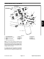
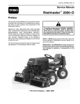
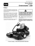
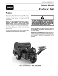
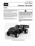
1
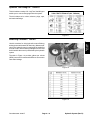
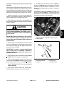
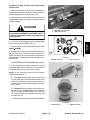
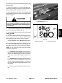
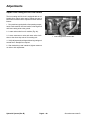
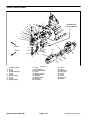
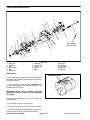
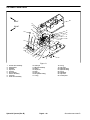
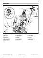
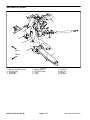
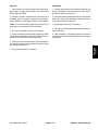
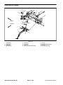
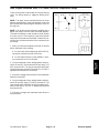
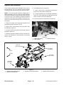
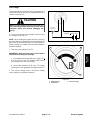
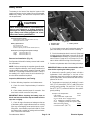
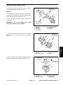
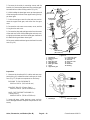
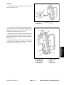
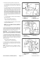
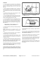
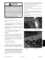
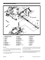
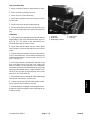
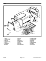
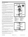
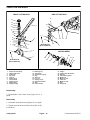
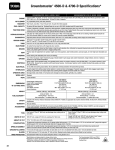
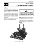
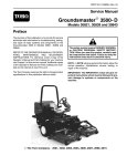
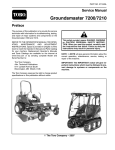
Installation
3
1. If the ring gear was removed from the differential
case, use medium strength Loctite thread locker and
tighten the mounting screws from 22 to 25 ft-lb (30 to
34 N−m).
2
1
2. Apply molybdenum disulfide lubricant (Three Bond
1901 or equivalent) to the splines and bearing surfaces
of the differential pinion gears, pinion washers and side
gears.
3. Install the side gear shims and side gears in their
original location in the differential case.
4. Place the differential pinion gears and pinion washers in their original location in the differential case. Temporarily install the differential pinion shaft.
Figure 37
1. Vise
2. Differential gear case
3. Dial indicator
More than 35% total tooth contact
5. Secure the differential case in a soft jawed vise. Position a dial indicator on a tooth of the differential pinion
gear. Press the pinion and side gear against the differential case and measure the pinion gear to side gear backlash (Fig. 37).
PINION GEAR TO SIDE GEAR BACKLASH:
0.004 to 0.016 in. (0.10 to 0.40 mm)
1/3 to 1/2 of entire width
from small end of tooth
6. Adjust backlash by increasing or reducing side gear
shim thickness.
NOTE: Side gear shims are available in 0.043 in. (1.10
mm), 0.047 in. (1.20 mm) and 0.051 in. (1.30 mm) thickness.
7. Apply gear marking compound, such as DyKem
Steel Blue lightly over several gear teeth.
8. While applying a light load to either side gear, rotate
either pinion gear until the side gears have made one
complete revolution.
9. Ideal tooth contact should cover more than 35% of
each tooth surface. The contact area should be in the
center of each tooth and extend 1/3 to 1/2 way across
each tooth from the toe (small) end (Fig. 38).
10.Adjust side gear shims if necessary to correct tooth
contact. Recheck differential pinion gear to side gear
backlash if any changes are made.
Figure 38
12.Install differential gear assembly in right side axle
support half.
13.Coat a new o-ring with grease and install left side
axle support half. Tighten axle support case screws from
35 to 41 ft-lb (47 to 56 N−m).
14.Install input shaft/pinion gear assembly (see Input
Shaft/Pinion Gear in this section of this manual).
15.Coat new o-rings with grease, align differential shaft
splines with differential gear assembly and slide differential shaft assemblies onto axle support.
16.Install bevel gear case/axle case assemblies (see
Bevel Gear Case/Axle Case Assembly in this section of
this manual).
11. After backlash and tooth contact have been adjusted, align the hole in the differential pinion shaft with
the hole in the differential case and install a new spring
pin.
Axles, Planetaries, and Brakes (Rev. B)
Page 6 − 26 Rev. E
Groundsmaster 4000−D