1
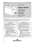
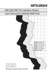
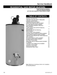
ELECTRIC WATER HEATER
INSTALLATION & OPERATING
INSTRUCTION MANUAL
THE MANUFACTURER OF THIS HEATER WILL NOT BE LIABLE FOR
ANY DAMAGE RESULTING FROM FAILURE TO COMPLY WITH THESE
INSTRUCTIONS. READ THESE INSTRUCTIONS THOROUGHLY
BEFORE STARTING.
For safety, convenience, and best performance, we recommend
this water heater be installed and serviced by a plumbing
professional.
238-43565-00H REV 8/10
TABLE OF CONTENTS
General Information ..........................................................
Installation .........................................................................
Locating The Water Heater ...........................................
Water Connections........................................................
Electrical Connections..................................................
Amperage Chart ..........................................................
GPH Recovery Capacities ..........................................
General Operation .............................................................
Thermostat Adjustment ................................................
Maintenance.......................................................................
Notes ..................................................................................
3
4
4
6
11
12
12
13
14
15
18
CONGRATULATIONS!
You have just purchased one of the finest water heaters
on the market today!
This installation, operation and instruction manual will
explain in detail the installation and maintenance of your
new Electric Water Heater. We strongly recommend that
you contact a plumbing professional for the installation of
this water heater.
We require that you carefully read this manual, as well as
the enclosed warranty, and refer to it when questions
arise. If you have any specific questions concerning
your warranty, please consult the plumbing professional
from whom your water heater was purchased. For your
records we recommend that you write the model, serial
number and installation date of your water heater in the
maintenance section in the back of this manual.
This manual should be kept with the water heater.
2
GENERAL INFORMATION
This water heater must be installed in accordance with local codes. In the
absence of local codes, install this water heater in accordance with national
or regional requirements.
The best efficiency and longest product life is obtained only when the water
heater is installed, adjusted and operated in accordance with these
Installation and Operating Instructions. The manufacturer will not be held
liable for damage resulting from alteration and/or failure to comply with these
instructions.
This water heater has been designed and listed for the purpose of heating
potable water. The installation and use of this water heater for any purpose
other than the heating of potable water may cause damage to the water
heater and create a hazardous condition.
CAUTION
Incorrect operation of this appliance may create a hazard to life and
property and may impair and shorten heater life.
Do not use this appliance if any part has been under water. Immediately call
a qualified service technician to inspect the appliance and to replace any
part of the control system which has been under water. Depending upon
individual circumstances, it may be necessary to replace the entire water
heater.
Make sure that the voltage being supplied to the water heater is according to
the voltage printed on the product rating plate.
DANGER
Do not store or use gasoline or other flammable, combustible or
corrosive vapors and liquids in the vicinity of this or any other
appliance.
IMPORTANT
Before proceeding, please inspect the water heater and its components for
possible damage. DO NOT install any damaged components. If damage is
evident, please contact the supplier where the water heater was purchased
or the manufacturer listed on the rating plate for replacement parts.
3
General Information continued-
A sacrificial anode(s) is used to extend tank life. Removal of any anode, for
any reason, will shorten the products useful life. In areas where water is
unusually active, an odor may occur at the hot water faucet due to a reaction
between the sacrificial anode and impurities in the water. If this should
happen, an alternative anode(s) may be purchased from the supplier that
installed this water heater. This will minimize the odor while protecting the
tank. Additionally, the water heater should be flushed with appropriate
dissolvers to eliminate any bacteria.
INSTALLATION
Locating The Water Heater
WARNING
Water heaters are heat-producing appliances. To avoid damage or injury,
there must be no materials stored against the water heater and proper care
must be taken to avoid unnecessary contact (especially by children) with
the water heater. UNDER NO CIRCUMSTANCES SHALL FLAMMABLE
MATERIALS, SUCH AS GASOLINE OR PAINT THINNER BE USED OR
STORED IN THE VICINITY OF THIS WATER HEATER OR ANY
LOCATION FROM WHICH FUMES COULD REACH THE WATER
HEATER.
This water heater must NOT be installed in any location where gasoline
or flammable vapors are likely to be present, unless the installation is
such to eliminate the ignition of gasoline or flammable vapors.
The location where this water heater is to be installed will be of utmost
importance. Before installing this water heater, consult the installation
section of these instructions. After reading these installation and operating
instructions, select a location for the water heater where the floor is level and
where the power supply and water connections are easily accessible. It is
recommended that the water heater be located near the center of greatest
hot water usage to reduce heat loss from the pipes.
DO NOT locate the water heater where water lines could be subjected
to freezing temperatures. Locate the water heater so that access
panels and drain valves are accessible.
4
Locating The Water Heater continued-
Water heater corrosion and component failure can be caused by the heating
and breakdown of airborne chemical vapors. Examples of some typical
compounds that are potentially corrosive are: spray can propellants, cleaning
solvents, refrigerator and air conditioning refrigerants, swimming pool
chemicals, calcium or sodium chloride, waxes and process chemicals.
These materials are corrosive at very low concentration levels with little or no
odor to reveal their presence.
NOTE: THE MANUFACTURER OF THIS WATER HEATER WILL NOT
ACCEPT RESPONSIBILTY FOR DAMAGE TO THE WATER HEATER
CAUSED BY EXPOSURE TO CORROSIVE VAPORS. DO NOT OPERATE
THE WATER HEATER IF EXPOSURE HAS OR WILL OCCUR. DO NOT
STORE ANY POTENTIALLY CORROSIVE COMPOUNDS IN THE
VICINITY OF THE WATER HEATER.
This water heater must be located in an area where leakage of the tank or
water line connections and the combination temperature and pressure relief
valve will not result in damage to the area adjacent to the water heater or to
lower floors of the structure. When such locations cannot be avoided, a
suitable drain pan must be installed under the water heater. The drain pan
must have a minimum length and width of at least 4 in. (10.2 cm) greater
than the diameter of the water heater. The drain pan, as described above,
can be purchased from your plumbing professional. The drain pan must be
piped to an adequate drain. The piping must be pitched for proper drainage.
This water heater MUST be installed indoors out of the wind and
weather.
Note: For California installation this water heater must be braced,
anchored, or strapped to avoid falling or moving during an earthquake.
See instructions for correct installation procedures. Instructions may
be obtained from the DSA Headquarters Office, 1102 Q Street, Suite
5100, Sacramento, CA 95811.
5
Water Connections
NOTE: BEFORE PROCEEDING WITH THE INSTALLATION, CLOSE THE
MAIN WATER SUPPLY VALVE.
After shutting the main water supply valve, open a faucet to relieve the water
line pressure to prevent any water from leaking out of the pipes while making
the water connections to the water heater. After the pressure has been
relieved, close the faucet. The cold water inlet line connects to the inlet
nipple at the base of the water heater. The hot water outlet line connects to
the nipple on top of the water heater. The fittings at the cold water inlet and
hot water outlet are dielectric waterway fittings with tapered male threads.
Make the proper plumbing connections between the water heater and the
plumbing system in the structure. Install a shut-off valve in the cold water
supply line.
CAUTION
If sweat fittings are to be used, DO NOT apply heat to the nipples on top
of the water heater. Sweat the tubing to the adapter before fitting the
adapter to the water connections. It is imperative that heat is not applied
to the nipples containing a plastic liner.
IMPORTANT
FAILURE TO INSTALL AND MAINTAIN A NEW, LISTED
TEMPERATURE-PRESSURE RELIEF VALVE WILL RELEASE THE
MANUFACTURER FROM ANY CLAIM, WHICH MIGHT RESULT FROM
EXCESSIVE TEMPERATURE AND PRESSURES.
If this water heater is installed in a closed water supply system, such as one
having a back-flow preventer in the cold water supply, provisions shall be
made to control thermal expansion. DO NOT operate this water heater in a
closed system without provisions for controlling thermal expansion. Your
water supplier or local plumbing inspector should be contacted about how to
control this situation.
After installation of the water lines, open the main water supply valve and fill
the water heater. While the water heater is filling, open several hot water
faucets to allow air to escape from the water system. After a steady stream
of water flows from the faucets, close them and check all water connections
for possible leaks. NEVER OPERATE THE WATER HEATER WITHOUT
FIRST BEING CERTAIN IT IS FILLED WITH WATER.
6
Water Connections continued-
WARNING
For protection against excessive temperatures and pressure, install
temperature and pressure protective equipment required by local codes,
but not less than a combination temperature and pressure relief valve
certified by a nationally recognized testing laboratory that maintains
periodic inspection of production of listed equipment or materials, as
meeting the Requirements for Relief Valves and Automatic Gas Shutoff
Devices for Hot Water Supply Systems, ANSI Z21.22, and the Standard
CAN1-4.4 Temperature, Pressure, Temperature and Pressure Relief
Valves and Vacuum Relief Valves. The combination temperature and
pressure relief valve must be marked with a maximum set pressure, not to
exceed the maximum working pressure of the water heater. The
combination temperature and pressure relief valve shall also have an
hourly rated temperature steam BTU discharge capacity not less than the
hourly input rating of the water heater.
Install the combination temperature and pressure relief valve into the
opening provided and marked for this purpose on the water heater
Note: Some models may already be equipped or supplied with a
combination temperature and pressure relief valve. Verify that the
combination temperature and pressure relief valve complies with local
codes. If the combination temperature and pressure relief valve does not
comply with local codes, replace it with one that does. Follow the
installation instructions above on this page.
Install a discharge line so that water discharged from the combination
temperature and pressure relief valve will exit within six (6) inches (15.3
cm) above, or any distance below the structural floor and cannot contact
any live electrical part. The discharge line is to be installed to allow for
complete drainage of both the temperature and pressure relief valve and
the discharge line. The discharge opening must not be subjected to
blockage or freezing. DO NOT thread, plug or cap the discharge line. It is
recommended that a minimum of four (4) inches (10.2 cm) be provided on
the side of the water heater for servicing and maintenance of the
combination temperature and pressure relief valve.
Do not place a valve between the combination temperature and pressure
relief valve and the tank.
7
Water Connections continued-
WARNING
Hydrogen gas can be produced in a hot water system served by this
water heater that has not been used for a long period of time
(generally two weeks or more). Hydrogen gas is extremely
flammable. To reduce the risk of injury under these conditions, it is
recommended that the hot water faucet be opened for several
minutes at the kitchen sink before using any electrical appliance
connected to the hot water system. If hydrogen is present, there will
probably be an unusual sound such as air escaping through the pipe
as the water begins to flow. There should be no smoking or open
flame near the faucet at the time it is open.
CAUTION
INCREASING THE THERMOSTAT SETTING ABOVE THE PRESET
TEMPERATURE MAY CAUSE SEVERE BURNS AND CONSUME
EXCESSIVE ENERGY. HOTTER WATER INCREASES THE RISK OF
SCALD INJURY.
This water heater can deliver scalding temperature water at any faucet in the
system. Be careful whenever using hot water to avoid scalding injury.
Certain appliances, such as dishwashers and automatic clothes washers,
may require increased temperature water. By setting the thermostat on this
water heater to obtain increased temperature water required by these
appliances, you might create the potential for scald injury. To protect against
injury, you should install an ASSE approved mixing valve in the water
system. This valve will reduce point of discharge temperature by mixing cold
and hot water in branch supply lines. Such valves are available from the
manufacturer of this water heater or a local plumbing supplier. Please
consult with a plumbing professional.
8
Water Connections continued-
Water temperature over 125°F
(52°C) can cause severe burns
instantly or death from scalds.
Children, disabled and elderly
are at highest risk of being
scalded.
Review this instruction manual
before setting temperature
at water heater.
Feel water before bathing or
showering.
Temperature limiting valves are
available.
APPROXIMATE TIME/TEMPERATURE RELATIONSHIPS IN SCALDS
120°F (49°C)
More than 5 minutes
125°F (52°C)
1½ to 2 minutes
130°F (54°C)
About 30 seconds
135°F (57°C)
About 10 seconds
140°F (60°C)
Less than 5 seconds
145°F (63°C)
Less than 3 seconds
150°F (66°C)
About 1½ seconds
155°F (68°C)
About 1 second
9
Water Connections continued-
The hot and cold water connections are identified on the top of the water
heater. Connect the hot and cold water lines to the installed nipples using
unions. Install a listed temperature-pressure relief valve in the opening on
the top of the water heater.
Figure 1
10
Electrical Connections
Before any electrical connections are made, be sure the water heater is full
of water and the manual shut-off valve located in the cold water supply line is
open. If the heating elements are not completely immersed in water at all
times, they will be damaged (burned-out) if energized for even a short period
of time. There is no warranty for burned-out heating elements. Before
proceeding verify a correct electrical connection has been made by checking
the rating plate and wiring diagram. The temperature-limiting device is of the
manual reset, trip-free type and has been factory installed to interrupt all
ungrounded power supply conductors in the event of thermostat failure.
The plumbing supplier in your area ordered this water heater wired at the
factory to comply with existing area codes, but local utility codes may require
or allow other circuitry. Consult your local power company to determine the
correct electrical hook-up in order to meet local utility and building codes and
in order to obtain the most economical rates. All electrical connections to
elements, thermostats, and terminal block have been made at the factory.
DO NOT alter any of the internal wiring. Wiring connections may loosen
during shipment. Check all connections for tightness.
To make the wiring connections to a power supply, follow the steps below.
A) Remove the control box cover panel.
B) Bring the power leads from an adequately sized fused disconnect switch
(not furnished with the water heater due to varying state and local codes)
and connect to the terminal block. Consult your local code and/or utility
authority about the correct wire size for the length of the wire required in
this installation. Longer wire lengths will usually require larger wire size.
C) This water heater must be properly grounded. A ground connection is
provided for connection to a properly sized ground. (See wiring diagram
for minimum required ground size. Wiring diagram is located on the
inside of the element cover)
D) Replace the control box cover panel.
11
Electrical Connections continued-
Heating Elements
To replace heating elements, disconnect power to the water heater, drain
tank and replace element. To remove a heating element, use a 1 1/2” screw
type element wrench that is usually available at places where plumbing
supplies can be obtained. Do not over-tighten the new element, as this will
cause distortion in the new element gasket. Once the element has been
replaced, follow the instructions “To Fill The Water Heater”. It is imperative
that the water heater is filled with water before the power is restored to the
heating elements.
Amperage Chart
Amperage
kW
Fuse Size
Ground Wire Size
220V 380V 415V 220V 380V 415V
3Ø
3Ø
1Ø
3Ø
3Ø
(AWG)
Input
1Ø
220V 380V 415V
6
27
9
8
35
12
10
10
14
14
9
41
14
13
60
20
20
10
14
14
12
55
18
17
70
25
25
8
12
12
13.5
61
21
19
80
30
25
8
10
12
10
15
68
23
21
90
30
30
8
10
16.5
75
25
23
100
35
30
8
10
10
18
82
27
25
110
35
35
8
10
10
GPH Recovery Capacities
kW
Temperature Rise
Input 40°F 50°F 60°F 70°F 80°F 90°F 100°F 120°F 130°F 140°F
6
62
50
41
35
31
28
25
21
19
18
9
93
74
62
53
47
41
37
31
29
27
12
124
99
83
71
62
55
50
41
38
35
13.5
140
112
93
80
70
62
56
47
43
40
15
155
125
103
89
78
69
62
52
48
44
16.5
171
137
114
98
86
76
68
57
53
49
18
186
149
124
106
93
83
74
62
57
53
Multiply kW input by 3,412 to determine BTU input:
Example: 54kW x 3412 = 184,248 BTU’s
Recovery Computation Formula
GPH= (watts x 3.412) / (8.25 x °Temp. Rise)
12
GENERAL OPERATION
Before closing the switch to allow electric current to flow to the
water heater, make certain that the water heater is full of water and
that the cold water inlet valve is open. Complete failure of the
heating element(s) will result if they are not totally immersed in
water at all times. Failure of the element(s) due to dry-firing is not
covered by warranty.
When the switch is closed, the operation of this electric water heater is
automatic. The water heater thermostat(s) are preset to the “HOT” setting to
provide a water temperature of approximately 140°F (60°C) or below in order
to reduce the risk of scald injury. Care must be taken whenever using hot
water to avoid scalding injury. Certain appliances require high temperature
hot water (such as dishwashers and automatic clothes washers).
CAUTION
Scalding may occur within five (5) seconds at a temperature setting of
140°F (60°C).
TO FILL THE WATER HEATER
1. Close the water heater drain valve by turning the knob clockwise.
2. Open the cold water supply shut-off valve.
3. Open several hot water faucets to allow air to escape from the system.
4. When a steady stream of water flows from the faucets, the water heater
is filled. Close the faucets and check for water leaks at the water heater
drain valve, combination temperature and pressure relief valve and the
hot and cold water connections.
5. Reconnect power supply to water heater.
TO DRAIN THE HEATER
Should it become necessary to completely drain the water heater, make sure
you follow the steps below:
1. Disconnect the power supply to the heater. Consult the plumbing
professional or electric company in your area for service.
2. Close the cold water supply shut-off valve.
3. Open the drain valve on the water heater by turning the knob counterclockwise. The drain valve has threads on the end that will allow
connection of a standard hose coupling.
4. Open a hot water faucet to allow air to enter the system.
To refill the water heater, refer to “TO FILL THE WATER HEATER.”
13
Thermostat Adjustment
CAUTION
Before adjusting thermostat(s), turn off power supply to the water heater.
The temperature of the water can be changed by adjusting the thermostat(s).
Before any work is done on the water heater, disconnect all power to the
water heater by opening the switch at the main electrical circuit breaker or
fuse box. Remove the access panels and fold the insulation outward away
from the controls. Set the thermostat(s) to the desired water temperature by
using a screwdriver to move the thermostat dial. The thermostat has been
factory preset to approximately 140°F (60°C) or below. Rotate the
temperature dial clockwise to increase water temperature. Replace the
insulation making sure the controls are well covered and the plastic terminal
shield has not been displaced; replace the access panel. The water heater
is now ready for operation and the main switch can be closed.
Figure 2
DANGER
Hotter water increases the risk of scald injury. Scalding may occur within
five (5) seconds at a temperature setting of 140°F (60°C). To protect
against hot water injury, install an ASSE approved mixing valve in the water
system. This valve will reduce point of discharge water temperatures by
mixing cold and hot water in branch water lines. A licensed plumbing
professional or local plumbing authority should be consulted.
Note: This water heater is equipped with an energy cut out device to
prevent overheating. Should overheating occur, turn off the electrical
supply to the water heater and contact a qualified service technician.
14
MAINTENANCE
IMPORTANT
The water heater should be inspected at a minimum of annually by a
qualified service technician for damaged components. DO NOT operate
this water heater if any part is found damaged.
Shut off the electric power whenever the water supply to the water heater is
off. Shut off the electric power and water supply, drain the heater completely
to prevent freezing whenever the building is left unoccupied during the cold
weather months. In order to insure efficient operation and long tank life,
drain the water heater at least once a month through the drain valve until the
water runs clear. Failure to do this may result in noisy operation and lime
and sediment buildup in the bottom of the tank. Check the temperaturepressure relief valve to insure that the valve has not become encrusted with
lime. Lift the lever at the top of the valve several times until the valve
operates freely and seats properly without leaking.
WARNING
When lifting lever of temperature-pressure relief valve, hot water will be
released under pressure. Be certain that any released water does not
result in bodily injury or property damage. The magnesium anode rod
should be inspected periodically and replaced when necessary to prolong
tank life.
The following, maintenance should be performed by a qualified service
technician at the minimum periodic intervals suggested below. In some
installations, the maintenance interval may be more frequent depending on
the amount of use and the operating conditions of the water heater. Regular
inspection and maintenance of the water heater will help to insure safe and
reliable operation.
1. Annually, check the operation of the thermostat(s).
2. Bi-annually, check the seal around the heating elements for leaks. If there
is any sign of leaking, disconnect the power supply to the water heater
and contact the plumbing professional that installed this water heater or a
qualified service technician.
15
Maintenance continued-
3. At least once a year, check the combination temperature and pressure
relief valve to insure that the valve has not become encrusted with lime.
Lift the lever at the top of the temperature-pressure relief valve several
times until the valve seats properly without leaking and operates freely.
WARNING
When lifting lever of temperature-pressure relief valve, hot water will be
released under pressure. Be certain that any released water does not
result in bodily injury or property damage.
4. If the combination temperature and pressure relief valve on the appliance
discharges periodically, this may be due to thermal expansion in a closed
water supply system. Contact the water supplier or local plumbing
inspector on how to correct this situation. Do not plug the combination
temperature and pressure relief valve outlet for any reason.
5. Monthly, drain off a gallon of water from the water heater to remove silt
and sediment.
WARNING! THIS WATER MAY BE HOT.
6. A combination sacrificial anode rod/hot water outlet nipple has been
installed to extend tank life. The anode rod should be inspected
periodically (every 2 years) and replaced when necessary to prolong tank
life. Water conditions in your area will influence the time interval for
inspection and replacement of the anode rod. Contact the plumbing
professional who installed the water heater or the manufacturer listed on
the rating plate for anode replacement information. The use of a water
softener may increase the speed of anode consumption. More frequent
inspection of the anode is needed when using softened (or phosphate
treated) water.
CAUTION
FOR YOUR SAFETY, DO NOT ATTEMPT TO REPAIR THERMOSTAT(S),
HEATING ELEMENTS, OR ELECTRICAL WIRING. REFER SUCH
REPAIRS TO A QUALIFIED SERVICE TECHNICIAN.
16
Maintenance continued-
Contact your local plumbing supplier or plumbing professional for
replacement parts or contact the company at the address displayed on the
rating plate of the water heater.
For faster and better service, please provide the part name, model, and
serial number(s) of the water heater(s) when ordering parts.
Manufactured under one or more of the following U.S. Patents: RE.34,534; B1
5,341,770; 4,416,222; 4,628,184; 4,669,448; 4,672,919; 4,808,356; 4,829,983;
4,861,968; 4,904,428; 5,000,893; 5,023,031; 5,052,346; 5,081,696; 5,092,519;
5,115,767; 5,199,385; 5,277,171; 5,372,185; 5,485,879; 5,574,822; 5,596,952;
5,660,165; 5,682,666; 5,761,379; 5,943,984; 5,954,492; 5,988,117; 6,142,216;
6,684,821; 7,063,132; 7,007,748; Other U.S. and Foreign patent applications
pending. Current Canadian Patents: 1,272,914; 1,280,043; 1,289,832; 2,045,862;
2,092,105; 2,107,012; 2,108,186; 2,112,515.
Complete the following information and retain for future reference:
Model No:
Serial No:
Service Phone
Days:
Nights:
Address:
Supplier:
Supplier Phone No:
17
NOTES
20
(To be performed ONLY by qualified service providers)
Commercial Electric Energy Saver:
E32-50S
E32-80R
E32-120R
Manual 239-47157-00B
Save this manual for future reference
E32 Medium Duty Commercial
Electric Water Heaters
Page
Service Procedure
Introduction ………………………………………………………………………. 2
---
Tools……………………………………………………………………………… 2
---
General Information ……………………………………………………………… 3
---
Sequence of Operation …………………………………………………………… 5
---
Field Conversion of kW, Voltage and Phase…………………………………….. 6
---
Troubleshooting ………………………………………………………………….
9
---
Heating Element Testing ……………...................................................................
11
E32-I
Line Voltage Testing………………...…………………………………………...
12
E32-II
Fuse and ECO Testing…........................................................................................
13
E32-III
Thermostat Operation Testing …….....................................................................
14
E32-IV
Thermostat Removal and Replacement …………………………………………. 15
E32-V
Heating Element Removal and Replacement ……………………………………. 16
E32-VI
Dip Tube and Anode Inspection and Replacement ……………………………… 17
E32-VII
Generic Parts List ………………………………………………………………... 18
---
This service manual is designed to aid service and maintenance professionals on the function, proper diagnosis and repair of
Bradford White medium duty commercial electric water heaters.
The text and illustrations in this manual provide step by step instructions to facilitate proper operation and troubleshooting
procedures. Contact the Bradford White Technical Support Group immediately if diagnosis can not be made using the
methods described in this service manual.
- Multi Meter.
- 1-½ Deep Well Socket (element removal).
- ¼" Nut Driver.
- Phillips Head Screw Driver.
- Thermometer.
- Drain Hose.
- Various Hand Tools: Pipe Wrench, Channel Locks, Pliers (common & needle nose), Wire cutters, Wire Strippers,
Flash Light.
Page 2
GENERAL INFORMATION
Commonly Used Formulas
Amps = Watts (for single phase units) Example 4500W/240V = 18.75A
Volts
Amps = Watts
(for balanced 3 phase units) Example 4500W/240V x 1.732 = 10.82A
Volts x 1.732
Watts = Amps x Volts Example 18.75A x 240V = 4500W
2
Ohms = Volts 2 Example (240V) / 4500W = 12.8 Ohms
Watts
BLACK
GREEN
RED
Grounding
Ungrounded
Ungrounded
240
120
120
Neutral
A
B
C
Neutral
A
C
208
208
A
C
277
120
240
240
208
BLACK RED
B
277
120
120
120
Neutral
120
120
RED
B
RED
480
240
BLACK RED
Page 3
277
480
RED
480
BLACK RED
GENERAL INFORMATION
Full Load Amperes-(Phase 1/Phase 3)
Input Kw
208V
240V
277V
380V
415V
480V
6
28.8/16.6
25/14.4
21.6
10
8.3
12.5/7.2
9
43.2/25
37.5/21.6
32.4
14
12.5
18.7/10.8
12
57.6/33.3
50/28.9
43.3
19
16.7
25/14.4
13.5
64.9/37.5
56.2/32.5
48.7
21
18.8
28.1/16.2
15
72.1/37.5
62.5/36.1
54.1
23
20.9
31.2/18
18
86.5/50
75/43.4
64
28
25
37.5/21.6
Surface Mounted Thermostats
E32 series medium duty commercial water heaters use only surface mounted thermostats. Surface mounted
thermostats are mounted into a bracket which holds the thermostat against the side of the tank. Surface mounted
thermostats respond to tank surface temperatures to sense a call for heat, set point temperature settings and high limit
(ECO) activation. It is import that the entire back surface of the thermostat is in full contact or flush with the tank. An
improperly mounted thermostat will lead to improper heater operation.
Manual
ECO (high limit)
Reset button
Surface Mount
Combination Thermostat/
ECO (high limit)
89T Series
Temperature
control Dial
Direct Immersion “Screw-in” Type Heating Element
1-½ Hex
Screw-in Flange
Terminal Block
0642
4500W 240V
RC02404524
Zinc Plated Copper or
Incoloy Sheath
Terminal Block
Screw
Element Rating Ink Stamped
on side of Terminal Block.
Page 4
SEQUENCE OF OPERATION
E32 series medium duty, field convertible commercial electric water heaters are designed to operate using single phase
or three phase service connections. One size fits all Internal fusing is factory installed for all units. When field
conversions are required, no fuse change is necessary. Three surface mounted thermostats operating independently
are used to control a corresponding heating element.
Fuse Block
Sequence of Operation.
1
2
3
Single phase line voltage is applied
across terminals L1 and L2 of terminal
block. Or Three phase line voltage is
applied to terminals L1 through L3 of
terminal block. Line voltage continues
through terminal block and fuse blocks
and connects to thermostats at
terminals L1 & L3.
Terminal Block
1
2
ECO (high limit) in thermostat is closed,
so there is line voltage present at
terminal L4 of thermostats and to one
side of each element.
ECO Closed
Water in tank is cold, so all thermostats
are closed at terminal T2 (calling For
heat). This completes the circuit and
allows current to flow through heating
element.
Power to one
side of element
4
4
As each thermostat is satisfied,
it opens at terminal T2 interrupting
current flow through the respective
element. The system is now in stand-by
mode, waiting for the next call for heat.
Thermostat closed
at terminal T2
Thermostat open
at terminal T2
Page 5
3
FIELD CONVERSION FOR:
KW, Voltage and Phase
The E32 series medium duty commercial electric water heaters are field convertible. This allows Qualified Service
Providers the ability to convert wattage, voltage and phase using a factory supplied conversion kit as required per the
installation. Underwriters Laboratories Inc. recognizes this procedure as herein presented and no deviation from these
instructions are allowed.
KW Conversion
All E32 series medium duty commercial water heaters are factory wired to the maximum electrical duty for which they
have been designed. Therefore, internal electrical components satisfy the maximum voltage and maximum electrical
current conditions.
These instructions do not allow for a modification that adds or deletes the number of heating elements originally supplied
with the heater; therefore such a modification must not be attempted.
Special factory prepared “Conversion Kits” must be used for these conversions. These kits contain the heating
elements, element gaskets and product labeling overlays related to the newly created electrical parameters.
18 KW heaters suitable for operation with 208vac cannot be created by conversion since there are no “kits” established
for this electrical system. These heaters can be obtained by ordering directly from the factory.
Conversion Kit Available
Total
Element
Heater KW Wattage
Required
---------- Kit Part Numbers ---------208 volts
240 volts
480 volts
6
2000
265-43942-13
265-43942-07
265-43942-01
9
3000
265-43942-14
265-43942-08
265-43942-02
12
4000
265-43942-15
265-43942-09
265-43942-03
13.5
4500
265-43942-16
265-43942-10
265-43942-04
15
5000
265-43942-17
265-43942-11
265-43942-05
18
6000
265-43942-18*
265-43942-12
265-43942-06
*265-43942-18 will require control box replacement (included in kit).
Following the heating element removal and replacement instruction on page 16, remove elements and replace with
elements from appropriate kit listed above.
The heaters rating plate will need to be modified because the conversion altered the electrical characteristics of the
heater. This rating plate is placed on every Commercial Electric water heater produced by Bradford White Corporation.
Element kits above contain rating plate label overlays related to the newly created electrical parameters. Follow the
instruction on page 8 For placement of overlays.
Voltage Conversion
1. Voltage conversion is accomplished by replacing the existing elements with elements that are rated at the
required voltage.
2. To accomplish this conversion refer to the above procedure for KW Conversion ---- Element Changes.
Control Box Conversion
1.
Open front panel of control box installed on water heater and
disconnect the (6) load wires from fuse blocks.
2.
Remove (4) screws joining control box to water heater and
remove control box.
3.
Install new control box onto the water heater by feeding the
wires through the back of the control box and reinstall (4)
mounting screws.
4.
Reconnect wires to new fuse blocks. Be certain to
match wire colors to Line side of fuse blocks.
Page 6
NOTICE
Control box conversion is ONLY required
when converting water heater to 18kw 208v
(Kit# 265-43942-18)
CAUTION
Use caution to not damage any of the wire
insulation when removing control box.
FIELD CONVERSION FOR:
KW, Voltage and Phase
Electrical Phase Conversion
Electrical phase conversion will require a change from single-phase to three-phase or an opposite conversion change
from three-phase to single-phase. Each of these conversions will be explained separately as follows:
Three-Phase to Single-Phase
1. Disconnect blue and yellow wires from terminal L-3 of the terminal block
2. Connect yellow wire to terminal L-1 of the terminal block. The black wires should remain connected to L-1 of the
terminal block as it was originally manufactured.
3. Connect blue wire to terminal L-2 of the terminal block. The red wires should remain connected to L-2 of the
terminal block as it was originally manufactured.
4. Field wiring for the heater power supply will eventually be connected to terminals L-1 and L-2 of the terminal block
when the product is installed.
Single-Phase to Three-Phase
1. Disconnect yellow wire from terminal L-1 of the terminal block
2. Disconnect blue wire from terminal L-2 of the terminal block
3. Connect blue and yellow wires to L-3 of the terminal block
4. Field wiring for the heater power supply will eventually be connected to terminals L-1, L-2, and L-3 of the terminal
block when the product is installed.
Fuse Block
Three Phase and Single Phase
Connections at Terminal Block
Phase
Terminal Block
L2
L3
L1
Single
BK & Y
Wires
R & BL
Wires
Three
BK
Wire
R
Wire
BL & Y
Wires
Terminal Block
E32 Series Phase Conversion Rating Plate Overlay Kits
Volt
6KW
Conversion Kit
Volt
9KW
Conversion Kit
Volt
12KW
Conversion Kit
208
240
480
265-45246-13
265-45246-07
265-45246-01
208
240
480
265-45246-14
265-45246-08
265-45246-02
208
240
480
265-45246-15
265-45246-09
265-45246-03
Volt
13.5KW
Conversion Kit
Volt
15KW
Conversion Kit
Volt
18KW
Conversion Kit
208
240
480
265-45246-16
265-45246-10
265-45246-04
208
240
480
265-45246-17
265-45246-11
265-45246-05
208
240
480
265-45246-18
265-45246-12
265-45246-06
The heaters rating plate will need to be modified because the conversion altered the electrical characteristics of the
heater. This rating plate is placed on every Commercial Electric water heater produced by Bradford White Corporation.
Phase conversion kits above contain rating plate overlays related to the newly created electrical parameters. Follow the
instruction on page 8 For placement of overlays.
Page 7
FIELD CONVERSION FOR:
KW, Voltage and Phase
Rating Plate Modification
The heaters rating plate will need to be modified because the conversion altered the electrical characteristics of the
heater. Refer to the illustration below that displays a typical commercial electric rating plate that is to be altered. This
rating plate is placed on every Commercial Electric water heater produced by Bradford White Corporation. Locate this
rating plate on the heater you have just converted.
BRADFORD WHITE CORPORATION
200 LAFAYETTE ST. MIDDLEVILLE MI 49333
Model No: E32-50S3
Serial No: ZB2564812
Cap.
50(gal.)/189.3(liters)
Press:
Test 300(psi), Working 150(psi)
Volts
240
Max Temp 180°
Phase
Three
Amps 43.3
Kw Each 6
Total Kw 18
Wattage Rating Based Upon 60 Hz
3 Elements
Locate the adhesive backed label (marked as part # 238-43990-00) (see illustration below) that was provided inside the
kit. It is marked with the new electrical data that is accurate for the conversion just executed. The kit will contain two
labels for this voltage and KW. One for three phase and one for single phase. Select the correct label for the electrical
phase in this conversion.
Volts
480
Max Temp 180°
Phase
Three
Amps 7.2
Kw Each 2
Total Kw 6
Wattage Rating Based Upon 60 Hz
Part number
3 Elements
238-43990-00
Remove the adhesive peel strip and place this label onto the rating plate in such a manner that the new electrical data
will appear in place of the data originally marked. Refer to the illustration below that displays the rating plate revision.
BRADFORD WHITE CORPORATION
200 LAFAYETTE ST. MIDDLEVILLE MI 49333
Model No: E32-50S3
Serial No: ZB2564812
Cap.
50(gal.)/189.3(liters)
Press:
Test 300(psi), Working 150(psi)
Overlay placed over old
rating plate data
Volts
480
Max Temp 180°
Phase
Three
Amps 7.2
Kw Each 2
Total Kw 6
Wattage Rating Based Upon 60 Hz
3 Elements
238-43990-00
Page 8
TROUBLESHOOTING
Most common cause for improper electric water heater operation can be linked to heating element
failure.
When troubleshooting an electric water heater with the incidence of “No Hot Water” or “Insufficient Amount of Hot
Water” It is always a good idea to check the heating elements first following the procedure on page 11.
Common Heating Element Failures Are:
1. Dry Firing. Element may be partially submerged in water or most likely, completely exposed with no water in
tank. In some cases sediment or lime build up around an element can eventually cause an air pocket, and
within seconds, result in a dry fired element. At this point the element becomes inoperative. When element
replacement is required, be sure tank is full of water prior to energizing the water heater.
2. Grounded Element. An element with a short circuit to ground will in most cases cause the circuit breaker in
the service panel to open or shut off. In some cases there may not be enough current draw for the circuit
breaker to open. This will allow the heating element to be in continuous operation resulting in over heated
water, limited only by the ECO or Energy Cut Off located in the thermostat. Repeated actuation of the ECO
reset button on the thermostat usually is the result of a grounded element.
3. Sediment build up. Slow hot water recovery can usually be traced back to sediment or lime build up around
heating element. Sediment build up can also over time cause a dry fired element.
The illustration below shows a common “Screw-In” type heating element identifying certain features commonly referred
to throughout this manual.
1-½ Hex
Screw-in Flange
Terminal Block
0642
4500W 240V
RC02404524
Zinc Plated Copper or
Incoloy Sheath
Terminal Block
Screw
Element Rating Ink Stamped
on side of Terminal Block.
Typical Direct Immersion “Screw-In”
Type Heating Element
Page 9
TROUBLESHOOTING
Quick Step Plan to Hot Water
WARNING
High voltage exposure. Use caution when
making voltage checks to avoid personal
injury.
1. TURN OFF power to water heater and check all wire
connections to insure they are tight and corrosion free.
2. Turn power “ON” and determine that line voltage is
present (see pg 12), and the high limit (ECO) has not
actuated (see pg 13).
3. Check for blown fuse (see pg 13).
4. Check for inoperative heating element (see procedure on page 11).
5. Check for proper thermostat operation (see pg 14). NOTE: Thermostat testing procedures
assume items 2, 3 and 4 above are in working order.
SYMPTOM
No Hot Water
PROBABLE CAUSE
CORRECTIVE ACTION
1. Check fuses or circuit breakers at service
panel.
2. Check water heater fuses.
3. Check all wire connections.
4. Check heating element(s). Replace as
needed.
5. Check thermostat(s) operation. Replace as
needed.
6. Check ECO. Reset or replace
thermostat(s) as needed.
1. No Power to heater.
2. Blown water heater fuses.
3. Loose wire connections.
4. Inoperative heating elements.
5. Inoperative thermostat.
6. Open ECO.
SERVICE
PROCEDURE
2. See Service Procedure
E32-III, Page 13
4. See Service Procedure
E32-I, Page 11.
5. See Service Procedure
E32-IV, Page 14.
6. See Service Procedure
E32-III, Page 13
Not Enough Hot
Water
1. Inoperative heating element.
2. Thermostat(s) set to low.
3. Inoperative thermostat(s).
4. Loose wire connection.
5. Sediment or lime build up on element(s).
6. High demand period.
7. Undersized heater.
8. Very cold inlet water to heater.
9. Plumbing connections reversed.
10. Damaged dip tube.
1. Check heating element(s), replace as
needed.
2. Increase thermostat setting.
3. Check thermostat(s), replace as needed.
4. Check all wire connection.
5. Remove heating element(s) and check for
lime build up.
6. Reduce demand.
7. Replace with larger heater.
8. Temper water to heater.
9. Correct plumbing connections.
10. Check dip tube, replace as needed.
1. See Service Procedure
E32-I, Page 11.
3. See Service Procedure
E32-IV, Page 14.
5. See Service Procedure
E32-VI, Page 16.
10. See Service Procedure
E32-VII, Page 17.
Slow Hot Water
Recovery
1. Sediment or lime build up on element(s).
2. Loose wire connections.
3. Inoperative thermostat(s).
4. Derated heating element installed.
1. Remove heating element(s) and check for
lime build up.
2. Check all wire connections.
3. Check thermostat(s), replace as needed.
4. Check terminal block of element for proper
voltage and wattage rating.
1. See Service Procedure
E32-VI, Page 16.
3. See Service Procedure
E32-IV, Page 14.
1. Thermostat(s) not in contact with tank.
2. Grounded heating element(s).
3. Thermostat set to high.
4. Inoperative thermostat(s).
5. Inoperative ECO.
6. Undersized water heater.
1. Position thermostat flush with tank surface.
2. Check heating element(s). Replace as
needed.
3. Adjust thermostat(s) to desired setting.
4. Check thermostat(s), replace as needed.
5. Check ECO, replace thermostat as
needed.
6. Replace with larger heater.
1. See Service Procedure
E32-V, Page 15.
2. See Service Procedure
E32-I, Page 11.
4. See Service Procedure
E32-IV, Page 14.
5. See Service Procedure
E32-III, Page 13.
1. Remove and clean heating elements.
Replace as needed.
1. See Service Procedure
E32-VI, Page 16.
Over Heated
Water or
Continues
Operation
Noisy (singing or
hissing) Elements
1. Lime formation on elements.
Page 10
SERVICE PROCEDURE E32-I
Heating Element Testing
Testing For Open Or Burned Out Element.
WARNING
High voltage exposure. Be sure power is turned
OFF to water heater prior to performing this
procedure.
Step 1. TURN OFF POWER TO WATER HEATER.
Step 2. Remove thermostat/element access cover(s)
from front of water heater. Remove insulation
and plastic cover from thermostat.
Step 3. Disconnect wires from heating element.
Step 4. Set multi-meter to “ohms” setting.
Step 5. Touch probes of multi-meter to screw
terminals of heating element
(see illustration 1).
Step 6. Reading should be 12.8 ohms (±6%) for a 240
volt, 4500 watt element, see table below:
2
Ohms = Volts
Watts
A reading outside the range using the formula
above (±6%), indicates a bad element and the
element must be replaced.
Ohms of electrical Resistance
Element Screw Terminals
Voltage Rating of Element
Illustration 1
Element
Wattage
208
240
480
2000
3000
4000
4500
5000
6000
21.6
14.4
10.8
9.6
8.7
7.2
28.8
19.2
14.4
12.8
11.5
9.6
115.2
76.8
57.6
51.2
46.1
38.4
NOTE
Disconnect
element
Wires
Testing For Heating Element Short Circuit To
Ground.
Step 1. TURN OFF POWER TO WATER HEATER.
NOTE
Disconnect
element
Wires
Step 2. Remove access cover(s) from front of water
heater. Remove insulation and plastic cover
from thermostat.
Step 3. Disconnect wires from heating element.
Element Screw Terminal
Step 4. Set multi-meter to “ohms” setting.
Meter Probe
Step 5. Touch one probe of multi-meter to either screw
terminal of heating element and the other on
the element flange (see illustration 2). There
should be no reading on the ohm meter. Any
reading indicates a grounded element and the
element must be replaced. Repeat this step for
the other screw terminal.
Element Flange
Illustration 2
Page 11
SERVICE PROCEDURE E32-II
Line Voltage Testing
Line Voltage Testing
WARNING
High voltage exposure. Use caution when
making voltage checks to avoid personal injury.
1. Turn “OFF” power to water heater.
2. Open control box located at the top of the heater to allow access to terminal block.
3. Set multi-meter to volts AC.
Check voltage across
L1 & L2 of terminal block
4. Turn power “ON” to water heater.
Single phase
Service from panel
5. For 3 phase service, go to step 7.
6. For single phase service, check voltage across terminals
L1 & L2 of terminal block (see illustration 3).
A) Rated voltage IS present, power to the water
heater is okay.
Illustration 3
B) Rated voltage NOT present, Check circuit breaker
at service panel.
Check voltage across
L1 & L2 of terminal block
Three phase
Service from panel
7. For 3 phase service check across L1 & L2 and across
L1 and L3 (see illustrations 4 & 5)
A) Rated voltage IS present, power to the water
heater is okay.
B) Rated voltage NOT present, Check circuit breaker
at service panel.
Illustration 4
Check voltage across
L1 & L3 of terminal block
Three phase
Service from panel
Illustration 5
Page 12
SERVICE PROCEDURE E32-III
Fuse Testing
Fuse Testing
1. Turn “OFF” power to water heater.
2. Open control box located at the top of the heater to
allow access to fuse block.
WARNING
High voltage exposure. Be sure power is turned
OFF to water heater prior to performing this
procedure.
3. Disconnect wire leads from fuse block. NOTE: It may be
necessary to label wires for proper re-connection when
finished.
4. Set multi-meter to the “Ohms” setting.
5. Check continuity across upper and lower screw terminal
of fuse block for each individual fuse, six total
(see illustration 6).
A) Continuity IS present, fuse is okay.
B) Continuity NOT present, Replace with new fuse
Class “G”, 480 Volt MAX, 30 Amp.
Illustration 6
ECO (high limit) testing
1. This procedure assumes line voltage and
fuses are in working order.
2. Turn power “OFF” to water heater.
3. Remove thermostat/element access cover(s) located
near the bottom of the water heater.
WARNING
High voltage exposure. Use caution to avoid
personal injury during this procedure.
4. Remove insulation and plastic cover from thermostat.
ECO reset
button
5. Turn power “ON” to water heater.
6. Check voltage across terminals L1 & L4 for all thermostats
(see illustration 7).
A) Rated Voltage IS present, ECO is okay.
B) Rated voltage NOT present, proceed to step 7.
7. Turn power “OFF” to water heater and firmly press ECO reset button on thermostat(s).
Turn power “ON” to water heater and recheck voltage across terminals L1 & L4 of thermostat(s).
A) Rated voltage IS present, the ECO has previously opened indicating the water in the tank, at
some point did overheat, Check the following:
1. Thermostat must be in full contact with tank.
Illustration 7
2. Be sure heating element(s) is not shorted to ground (see page 11).
3. Proper thermostat operation (see procedures on page 14).
B) Rated voltage NOT present, water in tank may be over heated.
1. If water is hot, turn “OFF” power to water heater and flow water through tank to cool below set point
of upper thermostat. Recheck voltage per step 6.
2. If water is cool, Replace thermostat(s).
Page 13
SERVICE PROCEDURE E32-IV
Thermostat Testing
Thermostat Operation Testing
WARNING
High voltage exposure. Use caution to avoid
personal injury during this procedure.
Water In Tank Is Cold With Power ON.
1. This procedure assumes line voltage, ECO and
elements are in working order.
2. Turn power “ON” to water heater.
3. Set multi-meter to “Volts AC”.
4. Check across terminals L1 & L3 of thermostat
(see illustration 8)
A) Rated voltage NOT present,
Check fuses.
B) Rated voltage IS present,
proceed to next step.
5. Check across terminals L4 and T2 of
thermostat (see illustration 9).
A) Rated voltage NOT present,
Recheck ECO. If ECO is okay,
replace thermostat.
Illustration 8
Illustration 9
B) Rated voltage IS present, okay thermostat is
calling for heat, proceed to next step.
6. Check across element terminals
(see illustration 10).
A) Rated voltage NOT present,
check wire connections from
thermostat to element.
B) Rated voltage IS present,
Repeat element testing
see page 11.
Water Temperature In Tank Is Above Thermostat Setting.
1. This procedure assumes line voltage, ECO and
elements are in working order.
Illustration 10
2. Turn power “ON” to water heater.
3. Set multi-meter to “Volts AC”.
4. See illustration 9 above, check across terminals L4 and T2 of thermostat.
A) Rated voltage IS present,
replace thermostat.
B) Rated voltage NOT present,
thermostat is okay.
C) Lower than rated voltage IS present,
recheck for grounded element
(see page 11).
Page 14
SERVICE PROCEDURE E32-V
Thermostat Removal and Replacement
Thermostat Removal
WARNING
High voltage exposure. Be sure power is
“OFF” when performing this procedure.
1. Turn power “OFF” To water heater.
2. Remove access cover(s) and insulation.
3. Remove plastic thermostat protector from thermostat(s).
4. Disconnect wires from thermostat terminals. It may be necessary to label wires for proper re-connection to
new thermostat.
5. Note thermostat temperature setting for proper setting of new thermostat.
6. Slide thermostat upwards and out of mounting bracket.
Thermostat Replacement
1. Use a stiff brush to remove any debris or loose scale from tank surface where new thermostat will be installed.
2. Slide new thermostat down into thermostat bracket until it snaps into place. IMPORTANT! Thermostat must set
completely flat or flush to tank surface. An improperly installed thermostat will cause improper water heater
operation.
3. Refer to the wire diagram located on the inside of the control box cover and re-connect wires to the thermostat. Be
sure wire connections are snug and corrosion free. Do not over tighten, doing so may damage thermostat.
4. Set thermostat to the original thermostat setting found on the old thermostat.
5. Re-install plastic thermostat protector.
6. Re-install insulation and access cover.
7. Restore power to water heater and verify proper heater operation.
Tank Surface
Proper Thermostat mounting
flush with tank surface
Thermostat
Improper Thermostat mounting.
Thermostat not flush with tank surface
Thermostat
mounting
bracket
Front View
Thermostat Mounting
Side View
Proper Thermostat
Mounting
Page 15
Side View
Improper Thermostat
Mounting
SERVICE PROCEDURE E32-VI
Heating Element Removal
and Replacement
WARNING
High voltage exposure. Be sure power is
“OFF” when performing this procedure.
Heating Element Removal
1. Turn power “OFF” To water heater.
2. Turn off cold water supply to heater. Connect hose to drain
spigot of water heater and route to an open drain. Open
a nearby hot water faucet to vent heater for draining. Open
drain spigot of water heater and allow heater to drain
to a point below the Element(s).
WARNING
Heater components and stored water may be
HOT when performing the following steps in
this procedure. Take necessary precaution to
prevent personal injury.
3. Close drain spigot and remove hose.
3. Remove access cover(s) and insulation.
4. Remove plastic thermostat protector from thermostat(s).
5. Disconnect wires from element terminals.
6. Remove element from tank using 1-½ deep well socket or appropriate wrench. Unscrew element counter-clockwise to
remove from tank.
7. Be sure to remove old element gasket from the tank. It is not recommended to be re-used.
Heating Element Replacement
1. Check element terminal block for proper electrical rating. NOTE: Some elements have dual ratings, be sure to check
all surfaces of the element terminal block (see illustration below).
2. Apply new element gasket to the new element. Be sure gasket is seated flat against element flange without rolls or
gaps (see illustration below).
3. Clean any debris from element fitting on tank. Lubricate element threads as needed with thread lubricant.
4. Thread new element clockwise into tank. Tighten element using 1-½ deep well socket or appropriate wrench. Do not
over tighten, over tightening may damage element gasket.
5. Reconnect wires to element, be sure connections are snug and corrosion free. Do not over tighten, doing so may
damage terminal block.
6. Resume water supply to heater, be sure tank is full of water and check for leaks.
7. Re-install plastic thermostat protector(s).
8. Re-install insulation and access cover(s).
9. To resume operation, BE SURE TANK IS FULL OF WATER and restore power to water heater. Verify proper heater
operation.
Element Rating.
Example: (4500 Watt, 240 Volt)
Date Code
0642
4500W 240V
RC02404524
Element Flange
Element Gasket Seated Flat Against
Element Flange Without Rolls or Gaps
Terminal
Block
Manufacturer Identification
Page 16
SERVICE PROCEDURE E32-VII
Dip Tube and Anode Inspection and
Replacement
Dip Tube Inspection and Replacement
WARNING
Heater components and stored water may be HOT when performing the following steps in
this procedure. Take necessary precaution to prevent personal injury.
Step 1.
Turn power “OFF” to water heater.
Step 2.
Turn off cold water supply to heater. Connect hose to drain spigot of water heater and route to an open drain.
Open a nearby hot water faucet to vent heater for draining. Open drain spigot of water heater and allow
heater to drain to a point below the inlet connection nipple.
Step 3.
Close drain spigot and remove hose.
Step 4.
Disconnect inlet nipple from plumbing system.
Step 5.
With an appropriate wrench, remove inlet nipple/dip tube from the water heater. Use caution not to damage
nipple threads.
Step 6.
Visually Inspect inlet nipple/dip tube. Inlet nipple/dip tube should be free of cracks and any blockage.
Hydro-jets located near the bottom of the dip tube should be open and free of any blockage.
Anti-siphon hole located approximately 6" from the bottom of nipple, should be free of any blockage.
Any damage such as cracks, restriction due to deformation or unintentional holes are not field repairable
and the inlet nipple/dip tube must be replaced.
Step 7.
Upon completion of inspection or subsequent replacement, reinstall inlet nipple/dip tube into heater. Connect
nipple to plumbing system, close spigot and remove drain hose, resume water supply and refill heater with
water.
Step 8.
To resume operation, BE SURE TANK IS FULL OF WATER and turn power “ON” to water heater.
Anode Inspection and Replacement
Step 1.
Turn power “OFF” to water heater.
Step 2.
Turn off cold water supply to heater. Connect hose to drain spigot of water heater and route to an open drain.
Open a nearby hot water faucet to vent heater for draining. Open drain spigot of water heater and allow
heater to drain to a point below the outlet connection nipple.
Step 3.
Close drain spigot and remove hose.
Step 4.
Disconnect outlet nipple from plumbing system.
Step 5.
With an appropriate wrench, remove outlet nipple/anode from the water heater. Use caution not to damage
nipple threads.
Step 6.
Visually Inspect outlet nipple/anode. Outlet nipple/anode should show signs of depletion, this is normal.
If depletion is ½ of the original anode diameter (original diameter approximately ¾”), replacement is
recommended. If any of the
steel core of the anode is exposed, replacement is recommended.
Step 7.
Upon completion of inspection or subsequent replacement, reinstall outlet nipple/anode into heater. Connect
nipple to plumbing system, close spigot and remove drain hose, resume water supply and refill heater with
water.
Step 8.
To resume operation, BE SURE HEATER IS FULL OF WATER and turn power “ON” to water heater.
Page 17
Generic Parts List
1. Hot Water Outlet Anode
2. T&P Relief Valve
3. Cold Water Inlet Dip Tube
4. Control Box
5. Ground Lug
6. Fuse
7. Fuse Block
8. Terminal Block
9. Brass Drain Valve
10. Thermostat Mounting Bracket
11. Element Gasket
12. Heating Element
13. Thermostat Surface Mount
14. Thermostat Protector
15. Thermostat/Element Access Cover
16. ASSE Approved Mixing Valve (optional)
Page 18
Email
[email protected]
[email protected]
www.bradfordwhite.com