1
119
Maintenance Section
Cutting Edges and End Bits - Inspect/Replace
i01326416
Cutting Edges and End Bits Inspect/Replace
SMCS Code: 6801-040; 6801-510; 6804-040;
6804-510
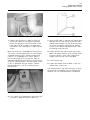
8. Raise the bulldozer blade and remove the
blocking. Lower the bulldozer blade to the
ground.
9. After you operate the machine for a few hours,
check all bolts for proper torque.
i01291242
Electronic Unit Injector Inspect/Adjust
SMCS Code: 1290-025; 1290-040
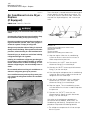
Be sure the engine cannot be started while this
maintenance is being performed. To prevent possible injury, do not use the starting motor to turn
the flywheel.
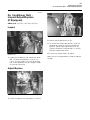
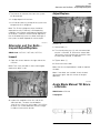
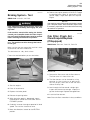
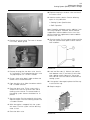
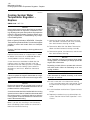
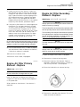
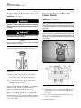
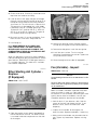
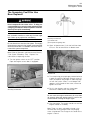
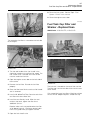
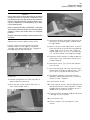
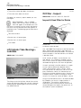
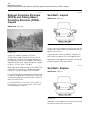
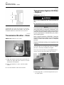
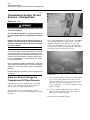
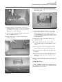
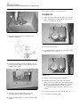
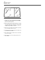
Illustration 228
g00039562
1. Raise the bulldozer blade and block up the
bulldozer blade. When you remove the cutting
edges and the end bits, maintain the bulldozer
blade at a minimum height.
2. Remove the bolts. Then remove the cutting edge
and the end bits.
Hot engine components can cause burns. Allow
additional time for the engine to cool before measuring/adjusting the unit injectors.
The electronic unit injectors use high voltage. Disconnect the unit injector enable circuit connector
in order to prevent personal injury. Do not come
in contact with the injector terminals while the engine is running.
3. Thoroughly clean all contact surfaces.
4. Inspect the opposite side of the cutting edge.
If the opposite side of the cutting edge is not
worn, turn the opposite side of the cutting edge
outward and install the cutting edge.
5. If both sides of the cutting edge are worn, install
a new cutting edge section.
Note: When the cutting edge is within 10 mm
(0.4 inch) of the bottom of the support, change the
cutting edge. Do not allow wear to occur on the
support.
6. If the bottom edge or the outside edge of the
end bit is worn, install a new end bit.
Note: When the end bit is within 10 mm (0.4 inch)
of the bottom of the support, change the end bit.
When the end bit is within 10 mm (0.4 inch) of the
outside edge of the support, change the end bit.
Do not allow any wear to occur on the support.
7. Install all bolts and tighten the bolts to a torque
of 1150 ± 150 N·m (850 ± 110 lb ft). Refer to
Operation and Maintenance Manual, “Torques for
Ground Engaging Tools”.
Electrical shock hazard. The electronic unit injector system uses 90-120 volts.
Adjust the electronic unit injector at the same
interval as the valve lash adjustment. The operation
of Caterpillar engines with improper adjustments
of the electronic unit injector can reduce engine
efficiency. This reduced efficiency could result in
excessive fuel usage and/or shortened engine
component life.
Refer to your machine’s Service Manual or your
Caterpillar dealer for the complete valve adjustment
procedure.