1
Section 3 – Functional Description
Sync Generat or Sect ion
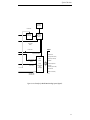
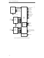
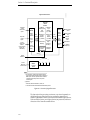
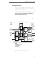
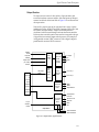
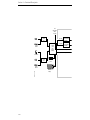
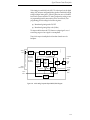
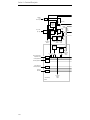
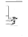
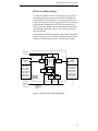
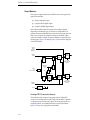
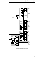
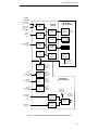
The Sync Generator circuitry takes an analog reference as an input and uses
it to create four internal clock signals. The reference input runs through a
bandpass filter and sync separator before being locked to the Model 3000
system clock at 14.313 MHz. The four clock signals consist of a Multiplex
clock, System clock, IQ clock and Subcarrier clock.
Sync derived from the reference is also used as the basis for deriving
horizontal and vertical pulses. Other time intervals are also derived for use
in the input and output modules.
Clock outputs and timing signals are placed on the backplane buses for use
throughout the Model 3000 frame.
Black and Test Generat ors Sect ion
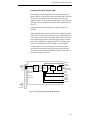
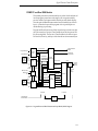
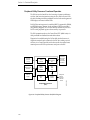
Signal generators on the Sync Generator module offer two video sources,
one provides the color black and the other allows selection of a variety of
test signals for alignment, fault diagnosis, and general use.
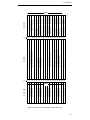
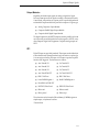
The test signals provide 9 different patterns (including black). A PROM on
the module is used to store the patterns. The patterns consist of the
following:
■
100% Color Bars
■
75% Color Bars
■
Multiburst
■
Multipulse
■
Pulse and Bar (composite)
■
Chroma Key Test Pattern (rainbow)
■
Horizontal Ramp—all bits (MSB1 and LSB2)
■
Horizontal Ramp (LSB bits only)
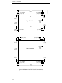
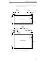
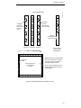
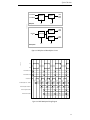
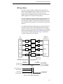
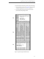
Screens produced by the test generator are divided into a top and bottom
half. Each of the screen halves can display a different test signal out of the
8 choices. For example, the top half of the screen could be set to display a
horizontal ramp, while the bottom half of the screen displays 100% color
bars.
1. MSB - Most Significant Bit.
2. LSB - Least Significant Bit.
3-36