1
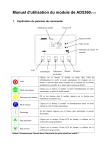
A30C Professional Auto Scanner
SERVICE MANUAL
CONTENT
Chapter One: Important Precautions
Chapter Two: Product Introduction
2.1 Brief Introduction
2.2 Function Introduction
2.3 Product Properties
2.4 Main Frame
2.5 Connectors and Package List
Chapter Three: FAQ( Frequently Asked Questions)
3.1 Common Diagnostic Conditions
3.2 Select Connectors
3.3 Equipment Connection
3.4 Common Problems and Answers
Chapter Four: Illustration of Main Interface
4.1 Boot-skin Interface
4.2 Main Menu Interface
4.3 Main Menu Interfaces Illustrated
Chapter Five: Guarantee Terms
5.1 Product Maintenance
5.2 How to Get Help
5.3 Guarantee Terms
5.4 Company Information
Chapter Six: The Diagnostic Socket Position
Chapter Seven: Referential Dataflow Program
7.1 BOSCH Datastream Program
7.2 DENSO Datastream
7.3 DF Dataflow Instruction
7.4 Electronic Control Component Function
WARNING
Honorable customers:
Great thanks for your purchase and use of AUTOSOS auto computer scanner.
This manual is particular for diesel auto computer scanner researched by AUTOSOS
corporation. Any company or individual must not make copy through electronic methods,
mechanical ways, printing, recording or any other ways without the authority of Shenzhen
AUTOSOS Technology Co., Ltd. (hereinafter called AUTOSOS corporation). The corporation will
not take any responsibilities for the results of its being misused to guide other operation rather than
using the AUTOSOS professional auto computer scanner.
Any machine trouble caused by the user’s abuse, mis-operation, unauthorized disassembly,
repair, operation without obeying the instruction, or unintentional losing will not be covered in the
range of free repair.
This instruction is particular to the professional vehicle repair and diesel ESC technicians.
If any questions about terms or content mentioned here, please contact us through the
following ways:
Website: http://www.autososcn.com
Address: Shenzhen AUTOSOS Technology Co., Ltd. A503 Room, Huibaojiang Building,
Longhua Minzhi Road, Bo’an District, Shenzhen SAR, China
Zip Code: +86-518000
Counseling Hotline: + 86-755-61354832
AUTOSOS corporation has registered its logo as “AUTOSOS” in China and several
countries aboard. In other countries where Shenzhen AUTOSOS Technology Co., ltd. has not
registered the logo, mark, domain name, icon and corporation name, AUTOSOS still has the
ownership over the matters mentioned above. Any other products and corporation brands referred
in this manual belong to their original company. Without the written consent of the owner anyone
must not use the logo, mark, domain name, icon and corporation names of the Shenzhen
AUTOSOS Technology Co., Ltd. and other corporations mentioned here.
Chapter One: Important Precautions
Operation Manual for A30C Diesel Auto Computer Scanner made by AUTOSOS
Corporation
●Please read the manual carefully before using the A30C professional auto computer scanner.
●The manual is edited according to the scanner’s current functions and product collocations.
If new functions and collocations are updated, the modified manual can be directly downloaded
from the AUTOSOS Corporation website: http://www.autososcn.com
●Please carefully read the “attention” and “notes” in the manual to make sure that you can
take safe and accurate test.
Attention and Notes for Mainframe Maintenance and Usage of A30C Diesel Auto Computer
Scanner
●Operation must be taken according to the safety regulations of automobile repair industry and
relevant diesel ECS repair. Special attention must be paid to the unfavorable environment factors:
acid, alkali, toxic gas and high pressure etc. to avoid damage.
●The auto battery fluid contains sulfuric acid which is harmful to skin, so please keep it from
direct contact with the mainframe shell, especially the LCD screen. Keep off fire.
●The exhaust gas contains various toxic compounds. During operation, do park the vehicles in
a place with good ventilation to avoid inhalation.
●Avoid touching the hot parts such as the radiator and vent pipe, for the engine are hightemperature when running.
●Before starting the engine, observe the hand brake and keep the gearlever to the neutral
position or to 【p】(automatic transmission), lest the vehicle rush out and hurt people when the
engine is started.
●Pull the parking brake, make the gearlever to the neutral position or to 【p】, and lower the
window at the driver’s side.
●If the engine can work, do warm up the vehicle to the normal temperature (water temperature
of about 80℃) and turn down the auxiliary electric appliances (such as the A/C system, lights and
the acoustics etc.).
●Find the auto diagnostic socket and make sure the cables are fine; otherwise, do not test in fear
of damaging the machine. Measure the diagnostic socket pressure when necessary.
Safety Warning
●Test under circumstance of good ventilation; if not, prolong the exhaust pipe to the outside.
●No smoking during the test, for it is inflammable.
●The auto battery contains sulfuric acid which is harmful to skin, so avoid direct contact with
skin, especially the eyes.
●Avoid contact with the radiator and exhaust pipe, for they are high-temperature when
engine is running.
●Before starting the engine, observe the hand brake and keep the gearlever to the neutral
position or 【p】(automatic transmission), lest the vehicle rush out and hurt people when the engine
is started.
●When the outside power supply is required, notice the electrode polarity and be sure to
connect the anode with the red alligator clip and the minus with the black one.
●When the scanner is used in the engine compartment, all the power supply cable, meter pen
and other tools should be away from the strap and the moving parts.
●No wearing watches, rings and large clothes in the engine compartment.
●During testing, please wear standard safety glasses.
Attention during the Use:
●As the delicate electronic instrument, the auto computer scanner should be placed and
removed carefully.
●Please wait patiently and do not operate it frequently when testing for the first time if the
program responses slowly.
●It is normal if the display screen flickers at the instant of engine’s starting.
●When the program breaks off or becomes snow-screened after the screen’s flickering, please
turn off the power supply and re-run the scanner to test.
●Make sure the instrument and the diagnostic plug base are well connected, lest the signal’s
interruption affects the testing. If it proves to be ill connected, re-plug and do not violently remove
the plug when using.
●During the test, try to put the scanner level with the screen upward.
●When using the connecting wires and sockets please tighten them with screws in fear of
breaking and damaging the connector during the movement. When pulling the socket, please hold
the front part rather than the connecting wire.
●Remove the machine with caution; Put it at safe place and avoid striking; cut off the power
supply when unused.
●Separate the fittings from the mainframe after using and put the fittings back into the chest
for fear of missing.
●The speed of upgrading-online is influenced by local network-speed, so please wait
patiently when the speed is low. Do not cut off the electricity during the upgrading if the mainframe
does not call for electricity-breaking, or the mainframe programs will be lost.
●Correct operation needs basic understanding of the auto checking and maintenance, and
relevant knowledge of the auto ECS (electronic control system).
Attention during Operating the Auto ECU
ECU:
When operating the vehicles equipped with the ECU, attention should be paid as follows:
●Do not place the magnetic objects like the wireless loudspeaker near the engine computer,
for the magnetism will damage the circuit and parts in the ECU.
●When the ignition switch is on, do not cut down the auto interior electric equipment
because the high instant voltage produced by the loop self-induction will cause damages to sensors
and the ECU.
●When taking repair near the engine computer and sensors, special attention should be paid
to avoid damage.
●Connect the socket of the engine ECU harness safely, otherwise the IC and other electronic
components inside the ECU will be damaged.
●When repairing or approaching the digital meter controlled by the ECU in winter, do wear
the earth metal belt; Nip one end of the belt to the vehicle body and twine the other around the wrist.
●When the vehicle needs welding, please cut down the ECU power supply in advance.
●To avoid damaging the ECU and sensors, please do not test the electric equipment related to
ECU without special instruction.
●Without special instruction in the testing program, please use the high impedance digital
instrument rather than the clock-hand ohmmeter to test the ECU and sensors.
Operation Circumstance for AUTOSOS Professional Diesel Auto Scanner
Condition
Requirement
TEMP ( operating)
-10~50℃(14~122°F)
TEMP (unoperated)
-20~70 ℃(-4~158°F)
Relative Humidity ( operating)
40 ℃, 15%~95%(no congealed frost)
Relative Humidity (unoperated)
65 ℃, 90%(no congealed frost)
Chapter Two: Product Introduction
2.1 Brief Introduction
A30C professional auto computer scanner belongs to diesel vehicle diagnostic
instruments
developed by Shenzhen Autosos Technology Co., Ltd. As the wonderful
integrated product of auto electronic applied technology and information technology,
these series of diesel auto scanner is characterized by structuration, standardization,
modulization and sustainable development. This series of auto scanner is produced
according to the market requirement for the diesel vehicles. Possessing the original
communication protocol and controller local net (CAN) communication protocol, it has
powerful expansion ability, and all kinds of functions can be combined freely.
2.2 Function Introduction
2.2.1 Read Computer Version Information
Read Computer Version Information means AUTOSOS A-30C manages to get information
through ECU software and hardware code.
2.2.2. Read Present DTC
Reading present DTC is realized through A-30C trouble memory of the ECU from which we
can know the present troubles and the reasons, and then we can analyze the vehicle trouble through
the content of DTC.
2.2.3. Read History DTC
Reading history DTC is realized through A-30C trouble memory of the ECU from which we
can know the previous troubles and the reasons, and then we can analyze the vehicle trouble
through the content of DTC.
2.2.4 Read Data Flow
Reading data flow is applied when the engine is in dynamic or static state.
AUTOSOS A-
30C calculates according to ECU internal parameters in convenience for users to learn total
parameters of each sensor, actuator and the whole vehicle. In this way, A30C analyzes the engine’s
working condition and evaluates the internal trouble information.
2.2.5 Actuator Component Testing
The purpose is to check whether the engine peripheral actuators are in good condition. The
functions of actuator component testing are different according to the type of ECU control. When
testing the components, if the conditions cannot be fulfilled, the testing should not proceed;
otherwise the engine maybe works abnormally. So before carrying out the actuator component
testing, we must learn its properties.
Note: When testing, the operation of each function cannot last over 1 minute; otherwise, the
actuator components may be damaged.
2.2.6. Read QR Code
QR code is the standard parameter designed when the ECU is shipped out of the factory. ECU
distinguishes the working conditions of each cylinder injector according to each QR code. This
function is used to read QR code of each cylinder.
2.2.7 Write QR Code
This function is used to write QR code. A new fuel injector cannot be recognized completely
by ECU after changing and ECU has to verify the renewed injector before working. This function
provides verifying interface between ECU and injector to realize complete matching.
2.2.8 Read VIN Code
VIN code is the only identification of the vehicle. Each vehicle has the only code when being
shipped out of the factory. This function is used to identifying vehicle.
2.2.9 Write VIN Code
After changing, a new ECU does not match the vehicle. This function is used to make
complete match between ECU and the vehicle.
2.2.10 Read EIN Code
EIN code is the only identification of the vehicle. Each vehicle has the only code when being
shipped out of the factory. This function is used to identifying vehicle.
2.2.11 Write EIN Code
After changing, a new ECU does not match the vehicle. This function is used to make
complete match between ECU and the vehicle.
2.2.12 Clear DTC
This function is used to clear DTC in the memory after the vehicle has been repaired, making
the ECU resume working normally.
2.3 Product Properties
■Quick System Operation Speed
The mainframe is equipped with advanced 32-bit embedded chip with large capacity
and brings you the convenience of quicker speed.
■Higher System Stability
The mainframe is developed by advanced techniques which make the applied system
programs work quickly and stably; with plenty of materials of vehicle types, the
product’s stability is well improved.
■Stronger System Independence
Testing programs for different modes of DONGFNG vehicle are stored in the memory
independently and able to be upgraded according to different modes.
■Swifter Diagnosis of the ECS:
The mainframe truss is designed with recent platform and more search engines,
realizing functions of manual searching, automatic searching and automatic diagnosing,
and improving working efficiency.
■More convenient upgrading:
The mainframe is equipped with USB2.0 upgrading connector for a U-disk. Upgrading
will be finished in a short time by downloading the upgrading program from the
company website.
2.4 Mainframe
The right picture illustrates the mainframe of A30C professional diesel auto computer
scanner. Besides, the scanner is matched with some fittings for connection and
upgrading online, such as testing extension line, battery extension line, auto crocodile
clip, cigarette lighter connector, DC 12V battery and other diagnostic connectors.
Technical Parameter
Item
Standard
Supply voltage
11-12VDC
Operating temperature
-10 - 50℃
Relative temperature
Less than 90%
USB connector
Standard USB connector
2.5 Connectors and Package List
2.5.1 Connectors section illustration
Picture 2-1-2 illustrates the connector section of
DONGFENG auto computer scanner:
Picture 2-1-2
⑧ DB25 diagnostic connector
⑨USB2.0 upgrading connector
⑩DC battery connector
specific fittings can be checked according to the package list attached to the mainframe.
The picture below demonstrates the relevant fittings:
Serial
Specification
Number
1
Mainframe number keyboard, including the
function number keyboard 【1,2,3,4,5,6,7,8,9,0】
2
Display screen
3
AUTOSOS logo
4
Function key 【ENTER】 and 【EXIT】
5
Function key 【����】for menu choosing
Function key 【RESET】, for checking the
6
computer resetting
7
Model label【A-30】, to signify the product name
8
DB25 diagnostic interface
9
USB interface,for the scanner’s upgrading
10
DC battery interface
2.5.2 Package List
Hardware fittings
Hardware
Standard
CPU
Double Core
Keyboard
11+6 film Keyboard
Screen
5.7# Blue LED Non-shadow
USB Interface
International USB2.0
Battery Interface
International 2.0 Battery Interface
Communication Interface
Duel row DB26 Interface
Body Shell
Strong ABS Plastic
Package Specification for A30C Professional Auto Computer Scanner
Serial
Model
Number
Number
Name
Amount
Remark
1
A-01
A30C Mainframe
1
√
2
A-16
Diagnostic Extension Cable
1
√
3
A-20
Cigarette Lighter Line
1
√
4
A-21
Power Supply Line
1
√
5
A-22
Stable-voltage Battery
1
√
6
A-23
Electronic Instruction
1
√
7
A-24
Maintenance Card, Certificate
1
√
8
A-25
Package List
1
√
9
A-26
Package Case
1
√
10
A-27
Exterior Package
1
√
11
A-03
Diesel Exclusive OBD
1
√
12
A-29
IVECO – 30 pin
1
√
13
A-30
BENZ – 6 pin
1
√
14
A-31
CUMMINS- 9 pin
1
√
15
A-32
CUMMINS-16 pin
1
√
16
A-33
BOSCH – 16 pin
1
√
17
A-34
DELPHI – 4 pin
1
√
18
A-35
Universal Connector
1
√
19
A-36
BOSCH -4 pin
1
√
20
A-37
IVECO-38 pin
1
√
21
A-38
DF YC – 4 pin
1
√
22
A-39
KINGLONG YC-4 pin
1
√
23
A-40
WANGTONG BOSCH – 4 pin
1
√
24
A-41
Advanced OBD
1
√
25
A-42
YC WITTE-3 pin
1
√
26
A-43
DENSO-12 pin
1
√
27
A-58
Fuse Pipe
1
√
Remark:Fittings are sometimes different according to different models in different regions, and
specific list should be in reference with the package list.
Chapter Three: FAQ( frequently asked questions)
3.1. Common Diagnostic Conditions
1. Check whether the vehicles or motors are equipped with diagnostic connector when the products
are shipped out of the factory.
2. Diagnostic connector position (the specific position please refer to Chapter Seven).
3. Power voltage: 12 v & 24 v.
4. Whether the ESC power supply is normal.
5. Vehicle name code and engine model.
6. Vehicle classification.
3.2
Select Diagnostic connector and diagnostic plug
base
The shape and definition of diagnostic plug differs according to different manufacturers.
According to diagnostic plug base model and ESC, choose the proper diagnostic connector and
check.
3.3. Equipment Connection
Preparation:
DF auto scanner mainframe, main cable, diagnostic connector.
Use the main cable to connect the mainframe and diagnostic connector and lock the screw.
Connect the diagnostic connector and the vehicle diagnostic plug base.
Turn on the ignition switch to ON or start the vehicle.
Open power switch of the scanner.
ENTER
Operate 【ENTER
ENTER】 to enter main menu.
3.4 Common Problems and Answers
?
1. Why some systems can be tested while other systems cannot for some vehicle
Answer: The reason for the phenomenon is that there are some errors in the testing line of
those systems. Only
through the reciprocal communications with the vehicle ECU by the
diagnostic plug testing line can the scanner read and clear DTC, read data flow and control
final components. Please use a multi-meter to measure diagnostic plug pins to see whether
they are in normal condition (including system ignition power, ground, communication line,
control unit, etc.).
2. In the process of diagnosing vehicles, communication is
always interrupted after entering
entering..
Answer: It is because there is interference during the communication. The testing extension
line should be away from strong interference source; and you’d better use the vehicle
battery to supply power for the scanner to make the exterior scanner hold common ground
friendly with the auto electric system to strengthen anti-interference ability.
3. Communication between the scanner and vehicle is
rather slow but can continue
continue..
Answer: The speed of communication is determined by the performance of the auto
computer. The speed in diagnosing PCM of lower baud rate is much slower than that of
higher baud rate with the same scanner. For example, in early times of GM, 160b was
adopted in the control system while 8192b is used in the new model of auto control system,
so the communication speeds are rather different.
4. The touch screen responses slowly in cold weather
weather..
Answer: It is caused by over-low temperature, for every component has its own suitable
working temperature (A30-C scanner’s suitable working temperature range :
-10℃~50°C).
If the temperature is too low, please turn on the power and preheat for 30 minutes.
5. Fail to Communicate with ECU
ECU..
Answer: please check whether the diagnostic connectors, program match with the vehicle
model.
6. Mistaken upgrading makes the program lost and fail to
initialized the U-disk
U-disk..
Answers: 1. Scanner with reset function can resume the original program by pressing the key
【RESET】.
Resetting procedure: press【RESET】for 10-30 seconds. Cut off and reconnect the power,
then press 【ENTER】 to resume. After resuming, restart the scanner.
2. Program without reset function needs to be sent back for repair.
Chapter Four: Illustration of Main Interfaces
4.1 Boot-skin
When connected well and push the switch button, one can see the initiation process; then the boot
skin will be shown as follows:
A30C Auto Scanner
Professional Diesel ENG Auto Scanner
Copyright @2009 AUTOSOS Tech CO., Ltd
Picture 4-1-1
Then, press ENTER button on the keypad one can see the next interface.
AUTOSOS
A30C
Welcome to use AUTOSOS auto scanner
Type: A30C for diesel vehicle
Tel: +86-755-61354832
Website: www. autososcn.com
SHENZHEN CHINA
ENTER QUIT▼▲
VER: AC. 09084
Picture 4-1-2
4.2 Main Menu Interface
After entering the booting interface, press ENTER to log in the main menu interface as
illustrated as the following picture 4-2-1. Then, the user can choose the right function
according to his need.
AUTOSOS
0. Common vehicle diagnosis
1. Quick diagnosis function
2. Intelligent search diagnosis
3. ECS classification diagnosis
4. Luminance adjusting display
5. System information
6. Special function
7. Upgrading online
ENTER QUIT ▼▲
VER:AC.09084
Picture 4-2-1
4.3 Common Vehicle Diagnosis interface
On the main menu interface, press the arrow keyboard【����】or the number key 【0】on the
left, choose【0. Common Vehicle Diagnosis】and press【ENTER】.The interface will turn up as the
picture 4-3-1:
AUTOSOS
00: Heavy Duty
01: Light Truck
02: Car
03:SUV Pickup
04: Special Vehicle
05: Construction Machinery
06: Coach
07: Bus
08: Generator Set
09: Marine System
ENTER QUIT ▼▲
VER:AC.09083
Picture 4-3-1
Here we choose Heavy as an example to show. Press the corresponding arrow key on the
right【����】or the number key【0】on the left, choose【00. Heavy Duty】and press【ENTER】.
The interface of heavy duty will turn up as the picture 4-3-2 which is illustrated on three pages in
total( one can press Pg Dn/Up to see them on screen):
AUTOSOS
00:Beijing Foton
01. CAMC
02. FAW Jiefang
03. BeiBen Benz
04. FAW Liuzhou Special
05. Yuchai Auto
06. Chongqing Auto
07. Dongfeng Auto
08 Isuzu
09. FAW Hongta
10. JAC Heavy duty
11. Nanjing Iveco Heavy duty
12. Changzhou Iveco
13.CDW Heavy duty
14. Isuzu(Asia)
15. Hino(Asia)
16. Volvo(Europe)
17. Ford(America)
18. Shaanxi Auto Heavy duty
19. Diesel ECS
20.CNHTC
21. GAC HINO
ENTER QUIT▼▲
VER:DF.09080
Picture 4-3-2
Now, we just take one as an example. Here we choose BEIJING FOTON. Press the corresponding
arrow key on the right 【����】 or the number key 【0】on the left , choose 【00. BEIJING
FOTON】 and press【ENTER】. After the wait interface, the required interface will turn up as the
picture 4-3-3:
AUTOSOS
00. SDE SOSC519BQQ-1
01. SDE SOSC819BB-1
02. WP CH23Bxxxxx
ENTER QUIT ▼▲
VER:AC.09083
Picture 4-3-3
Here, if well connected with the automobile, the user can start to choose the related system, eg,
SDE SOSC519BQQ-1 and press enter to be into diagnosis interface shown in picture 4-4-4. Then
he or she can operate the auto scanner through following the tips.
AUTOSOS
Choose:
Tester:
OBD16 convertor
Press 【ENTER 】or 【EXIT】
ENTER
EXIT
Ver: AC 09083
Picture 4-3-4
Similarly, as to other common vehicle types, such as car, special vehicles and construction
machinery and so on, the user can refer to the above process, of course with different interfaces to
be displayed.
4.4
Quick Diagnosis Function
Here, quick diagnosis function means that one can search the familiar power maker according
to his own automobile power used. Through classifying power maker, one can save some time
when using the diagnostic equipment. Back to the main interface, one press the arrow
keyboard【����】or the number key 【1】on the left, choose【1. Quick Diagnosis Funciton】
and press【ENTER】.The interface will turn up as the picture 4-4-1 which is illustrated on two
pages in total( one can press Pg Dn/Up to see them on screen):
AUTOSOS
00: Weichai Power
01:Chaochai Power
02:Dachai Power
03:Yuchai Power
04:Quanchai Power
05:Xichai Power
06:Shangchai Power
07:Yunnei Power
08:Yangchai Power
09:Changchai Power
10: Isuzu power
11: CNHTC Hangzhou ENG
12: Shanghai Hino
13: Huabei Power
14: Renauld’s power
15: SIDA Power
16: Iveco Power
17: Perkins power
18: Vovol Power
19: DEUTZ Power
ENTER EXIT
Ver: AC 09083
Picture 4-4-1
Here we choose BEIJING FOTON. Press the corresponding arrow key on the right
【����】 or the number key 【0】on the left , choose 【00. WEICHAI Power】 and press
【ENTER】. After the wait interface, the required interface will turn up as the picture 4-4-2 (one can
press Pg Dn/Up to see the left ones on screen):
AUTOSOS>Select system
00. WP12.270
01. WP12.300
02. WP12.336
03. WP12.375
04. WP12.400
05. WP12.430
06. WP12.460
07. WP10.240
08. WP10.270
09. WP10.290…
ENTER
EXIT
Ver: AC 09083
Picture 4-4-2
Then one can choose the system, (hereinafter we always choose the first one as the example, and the
user can do as he wishes) Since we choose 【00. WP12.270】, and the diagnostic interface will turn
up as the following picture 4-4-3
AUTOSOS
0. Static Data
1. Dynamic Data
ENTER
EXIT
Picture 4-4-3
Version: AS09072
Then choose 【0. Static Data】 and press ENTER, and one can enter the diagnosis interface and
choose the proper connector as required, which is demonstrated as follows:
DF Auto Scanner
0. Trouble Diagnosis
ENTER QUIT▼▲
VER:AC.09083
Picture 4-4-4
DF Auto Scanner
Choose
Tester
OBD 16 connector
Press ENTER or QUIT.
ENTER QUIT ▼▲
VER:AC.09083
Picture 4-4-5
If well communicated with auto computer, user can do as required to diagnose his auto with
right connector. And this is the demo for quick diagnosis.
4.5 Intelligent Search Diagnosis
Back to the main interface, and it is time to introduce the intelligent search diagnosis function
which means a shortcut through which one can choose the first letter of the vehicle type to log in
the right vehicle diagnosis interface .
Press the arrow keyboard【����】or the number key
【2】on the left, choose【2. Intelligent Search Diagnosis】and press【ENTER】.The interface will t urn
up as the picture 4-5-1:
AUTOSOS A30C
Choose the initial of the vehicle type:
ABCDEFGHIJKLMNOPQ
RSTUVWXYZ
ENTER QUIT ▴▾◄▸ 0-9
Ver:AC 09083
Picture 4-5-1
For example, if we want to test a vehicle with name of ANKAI, we can choose A on the above
interface and the following interface will appear step by step.
Select Maker
00: ANKAI Coach
ENTER ▴▾◄▸ 0-9
Ver:AS 09083
Picture 4-5-2
Select Maker
00: XICHAI CH24DKAYY-1
01: XICHAI CH24DKAYY-2
02: WEICHAI CH23DKAQQH
03: SDE SOSC519DKKQM
04: SDE SOSC819DKCCH
ENTER QUIT ▴▾◄▸ 0-9
Ver:AC 09083
Picture 4-5-3
Then one can choose the system, (hereinafter we always choose the first one as the example, and the
user can do as he wishes). Since we choose【 00. XICHAI CH24DKAYY-1】, and the diagnostic
interface will turn up as the following picture 4-4-3
AUTOSOS
0. Static Data
1. Dynamic Data
ENTER
EXIT
AS09072
Picture 4-5-4
Version:
Then choose 【0. Static Data 】and press ENTER, and one can enter the diagnosis interface and
choose the proper connector as required, which is demonstrated as follows:
DF Auto Scanner
0. Trouble Diagnosis
ENTER QUIT▼▲
VER:AC.09083
Picture 4-5-5
DF Auto Scanner
Choose
Tester
OBD 16 connector
Press ENTER or QUIT.
ENTER QUIT ▼▲
VER:AC.09083
Picture 4-5-6
If well communicated with auto computer, user can do as required to diagnose his auto with
right connector. And this is the demo for intelligent search diagnosis.
4.6 ECS Classification Diagnosis
This mainframe can be conveniently upgraded online with a U-disk, and on the main interface, the
user Press the corresponding arrow key on the right【����】 or the number key【3】on the left,
choose 【3. ECS Classification Diagnosis】and press 【ENTER】.The interface will turn up as the
picture 4-6-1:
AUTOSOS
00: ECS
ENTER
EXIT
Version: AS09072
Picture 4-6-1
On this interface, user can press ENTER to continue; otherwise, he can press RESET to quit. The
upgrading process will be shown when user waits. When finished, the tips will appear for the user to
shut the power supply and restart the mainframe.
4.7 Luminance Adjusting Interface
The mainframe luminance also can be adjusted, and on the main interface, the user press the
corresponding arrow key on the right 【����】 or the number key 【4】on the left, choose
【4. LAdjusting】and press 【ENTER】.The interface will turn up as the picture 4-7-1:
ADJUSTING LUMINANCE
DONGFENG
DONGFENG
123456789012345678901234567890123456
ABCDEFGHIJKLMNOPQRSTUVWZYZ1234567
890abcdefghijklmnopqrstuvwxyz+_*&^%$#
ABCDEFGHIJKLMNOPQRSTUVWXYZ?%$#@!
SAVE:ENTER, QUIT: EXIT, ADD:UP, LOWER:DOWN
ENTER QUIT ▼▲
VER:AC.09084
Picture 4-7-1
4.8 System Information Interface
On the main interface, the user Press the corresponding arrow key on the right 【����】 or the
number key【5】on the left, choose【5. System Information】and press【ENTER】.The interface of
the system information of this mainframe will turn up as the picture 4-8-1:
A30C Auto Scanner
Type:A30C for diesel
Machine code: S300990S3083
Software version: 09084
Hardware version: 29.1
System version: 28.8
Press 【ENTER】to exit.
ENTER QUIT ▼▲
VER:DF.09080
Picture 4-8-1
4.9 Special Function
On the main interface, the user Press the corresponding arrow key on the right 【����】 or the
number key 【6】on the left, choose 【6. System Information】and press 【ENTER】.The special
function interface of this mainframe will turn up as the picture 4-9-1:
A30C Auto Scanner
0. Demonstration
1. ECS special terms
ENTER QUIT ▼▲
VER:AC.09084
Picture 4-9-1
4.9.1 Demonstration Interface
As shown in the picture 4-9-1 , one can choose the number key 【 0 】 on the left, choose 【 0.
Demonstration】and press 【ENTER】.The demo interface of this mainframe will turn up as the
picture 4-9-2:
AUTOSOS A30C
Demo:
press 【ENTER】or 【QUIT】
ENTER ▴▾◄▸ 0-9
Ver:AS 09084
picture 4-9-2
4.9.2 Demonstration Interface
As shown in the picture 4-9-1 , one can choose the number key 【 1 】 on the left, choose 【 1.
Demonstration】and press 【ENTER】.The demo interface of this mainframe will turn up as the
picture 4-9-3:
ECS Terms
Please select the initial of the abbreviations.
ABCDEFGHIJKLMNOPQ
RSTUVWXYZ
press 【ENTER】or 【QUIT】
ENTER ▴▾◄▸ 0-9
Ver:AS 09084
Picture 4-9-3
ECS Terms
(1) A & M 安装与维护
Assembly and maintenance
(2) AC generator 交流发电机
Alternative current generator
(3) A/C 空调
Air conditioner
press 【ENTER】or 【QUIT】
ENTER ▴▾◄▸ 0-9
Ver:AS 09084
Picture 4-9-4
4.10 Upgrading Online Interface
This mainframe can be conveniently upgraded online with a U-disk, and on the main interface, the
user Press the corresponding arrow key on the right【����】 or the number key【7】on the left,
choose【7. Upgrading online】and press【ENTER】.The interface will turn up as the picture 4-10-1:
Entered USB interface, refer to the tips.
important reference tips
Keep stable power supply connection; do not
remove your mainframe. Please read the specification
file: autosos.txt, and press 【ENTER】to log in the main
downloading interface.
Press 【ENTER】to continue.
ENTER QUIT ▼▲
SHENZHEN CHINA
Picture 4-4-1
On this interface, user can press ENTER to continue; otherwise, he can press RESET to quit. The
upgrading process will be shown when user waits. When finished, the tips will appear for the user to
shut the power supply and restart the mainframe.
4.7 Technique parameters:
Machine model: used for identifying the specific type of the scanner.
Machine code: referring to the code when the scanner shipped out of the factory; used for after-sale
service and quality maintenance; the only identification code of the machine.
Operation system version: the software platform version, used for the upgrading service to make
sure the product’s adaptability.
Diagnostic system version:
the diagnostic program upgrading version, used for diagnostic
program’s upgrading identification, convenient for customers to update the software.
Hardware version information: used for identifying the hardware updating and the hardware
modifying status.
Chapter Five: Guarantee Terms
5.1 Product Maintenance
■When unused please put the scanner at the flat, dry and dustless place of suitable
temperature.
■Do not expose the scanner to the strong sunlight and the heating device.
■Do not put it near the stove or at the place where it may be eroded by smoke, water
and oil.
■No disassembly without professional guidance. When the mainframe is dirty, please
shut down the machine and keep power off, then clean the screen with the wet soft
cloth.
■When unused for long, operate the scanner at a certain time to avoid damage of
long-timed humidity.
5.2 How to Get Help
Users of A30C diesel auto computer scanner are provided with powerful help support
in the machine and online.
If the users want to know the latest product functions or auto diagnosis information, please land the
company web site: http://www.autososcn.com, or landing the technique forum for auto computer
scanner: http://www.autososcn.com/autososbbs
5.3 Guarantee Terms
1. Under the conditions of the following items and assuring of having sent the sub
copy of warranty card to Shenzhen AUTOSOS technology Co., Ltd (hereinafter Abr. as
AUTOSOS Corporation) for register, the products with defects in material or
technology are included in free maintenance service provided by AUTOSOS
Corporation.
2. Please make sure that you have read the Guarantee terms carefully, otherwise
AUTOSOS Corporation will assume that you have agreed the terms after the sub
copy of warranty card has registered.
3. The product you hold must be bought from the authorized dealer of AUTOSOS
Corporation, otherwise, the buyer must pay for the maintenance cost.
4. The following items are not in the range of guarantee: service manual, exterior
and interior package, accessory power, compact disk, free offer products, flimsy
items etc.
5. The product can enjoy the rights of maintenance and upgrading service for free
within 12 months (subject to the date of invoice and guarantee card).
6. If the product is found non-human error performance failure within 7 days after
bought, the buyer can choose to maintain or change for another one of the same
model.
7. Your product cannot receive the free maintenance service in the following cases:
1)The errors and defects which do not result from the product’s quality: the error
caused by incorrect operation, disobedience to service manual instruction, crash,
falling, self-disassembly, improper fittings connection, crush led by improper
transportation and storage , etching and tarnishing made by leakage of the food, etc.
2) Natural wear and tear: the shell, key, LCD touch screen, and accessory, etc.
3) The discord of the serial number and barcode of the guarantee card, the deletion,
alteration or damage of the quality examination label or barcode.
4) The maintenance and modification without the permission of AUTOSOS
Corporation.
8. You can take the following measures if there are quality problems within the
guarantee period:
1) You can send the product to the designated service place by AUTOSOS
Corporation to maintain, please enclose with the copies of the invoice, Guarantee card
and service requirement instruction.
2) You can dial the service hotline number:+86-755-61354832 to acquire proper
service information.
9. In the process of service, you have to pay the cost before you have sent it to the
designated site, including the package, transportation and insurance fees, etc.
10. The free maintenance service you enjoy according to Guarantee terms is the only
method to avoid the damage resulting from product defects; AUTOSOS Corporation
has no responsibility for your direct and indirect damage.
11. All the changes of Guarantee information, product functions and specification will
be published in the promotional materials and website. No special notice for individual.
5.4 Company Information
Company Name: Shenzhen AUTOSOS Technology Co., Ltd.
ADD: A503 Room, Huibaojiang Bulilding, Longhua Minzhi Road, Bao’an District,
Shenzhen SRA, China
Zip Code: +86-518000
TEL: +86-755-61354832
FAX: +86-755-82926595
WEB: http://www.autososcn.com
Chapter Six: The Diagnostic Socket Position
Picture 7-1
Picture 7-2
Jiefang Cellon Ⅱ diagnostic socket is standard round
Jiefang Cellon Ⅲ diagnostic socket is standard
16 pin; Lies on the right side of the dashboard, under
round 16 pin; Lies on the right side of the
the blower.
dashboard, left side of the steering wheel.
Picture 7-4
Picture 7-3
FAW liuzhou special vehicle diagnostic plug is
Liuzhou Ballon vehicle diagnostic plug is
standard round 16 pin; lies on the right side of
standard round 16 pin; lies on the low left of the
console, under A-pillar.
driver’s seat in the cab.
Picture 7-5
Picture 7-6
Foton Omax diagnostic socket is standard round 16
Wuzhoulong diagnostic socket is single row 4 pin;
pin; lies behind of gear rod in the cab, above the
lies on the right side of steering wheel.
ECU.
Picture 7-7
Picture 7-8
Dongfeng Tianlong diagnostic socket is standard
Dongfeng Cummins Power diagnostic socket is 3
round 16 pin; lies on the fuse frame on the tight of
pin; lies on the left side of engine and near the
console.
ECU.
Chapter Seven: Introduction of Referential Data
Flow Program
7.1 BOSCH Data Flow Program
Name of Data stream
High Speed
Idle Speed
Static State
Motor Speed(r/min)
2396
598
0
Coolant Temperature(℃)
76.13
71.63
76.58
Battery Voltage(V)
28.17
28.33
27
Accelerator Panel Position Sensor 1(V)
3.8
0.74
0.74
Accelerator Panel Position Sensor 2(V)
1.92
0.38
0.38
Calculated Accelerator Panel Position (%)
100
0
0
Preinjector 1 Injection Time(ms)
0
529
0
Main Injection Lasting Time(ms)
686
516
0
Injection Amount (mg)
26
5.6
58.7
Set Rail Pressure (Mpa)
86.3
41.8
40
Actual Rail Pressure(Mpa)
86.8
42.2
0
Common-Rail-Einspritzung Pressure Sensor
2.43
1.42
0.49
Fuel Adaption Unit (mA)
1324
1443
401
Fuel gauge unit pulse duty cycle (%)
17.68
19.08
7.13
Coolant Temperature Sensor Voltage(V)
1.06
1.18
1.05
Air Pressure Sensor Voltage(V)
4.04
4.03
4.03
Atmospheric Pressure (hPa)
1022
1021
1021
Actual Boost Pressure (hPa)
1306
1024
1016
Intake Air Temperature Sensor Voltage(V)
2.85
2.89
2.56
Intake Air Temperature (℃)
28.9
28.0
35.4
Engine Oil Temperature (℃)
82.3
77.9
78
Fuel Temperature (℃)
76.1
76.1
76.3
Running Speed (KM)
0
0
0
Engine Control Trouble Indicator Lamp OFF
Open circuit
Open circuit
Open circuit
Brake Switch 1 ON
closed
-
-
Brake Switch2 OFF
-
Open circuit
Open circuit
Clutch Switch No Operation
closed
closed
closed
Engine Trouble Indicator Lamp
ON
ON
ON
Main Brake Switch Logical Value
OFF
OFF
OFF
Assistant Brake Switch Logical Value
ON
ON
ON
Clutch Switch
No operation
No operation
No operation
A/C Switch
ON
ON
ON
Parameter Name
Unit
Voltage(V)
7.2 Denso Datastream
Serial
Parameter Name
Unit
Number
1
Serial
Number
Motor speed
R/min
29
Cylinder 5 (Injector#2) Mm3/st
FCCB modification
value
2
Injection amount
mm3/st
30
Cylinder 6 (Injector#4) Mm3/st
FCCB modification
value
3
Coolant water
0C
31
temperature
Injection pump
0CA
closing timing
4
Intake pressure
Kpa
32
Fuel temperature
0C
5
Injection timing
0CA
33
Ignition state
ON/OFF
6
Pre injection amount
Mm3/st
34
Start-up state
ON/OFF
7
Pre injection timing
0CA
35
NE activation state
ON/OFF
8
Throttle opening
%
36
G activation state
ON/OFF
9
Vehicle speed
Km/h
37
Park switch
ON/OFF
10
Power supply
V
38
Diagnostic switch
ON/OFF
Kpa
39
Preheating relay
ON/OFF
voltage
11
Atmospheric
pressure
12
Travel mileage
Km
40
Clutch switch
ON/OFF
13
Coolant temperature
V
41
Neutral switch
ON/OFF
V
42
A/C switch
ON/OFF
V
43
EXB switch
ON/OFF
V
44
Idle speed switch
ON/OFF
sensor voltage
output
14
Intake temperature
sensor voltage
output
15
Fuel temperature
sensor voltage
output
16
Common rail
pressure voltage out
put
17
Air pressure sensor
V
45
Brake switch
ON/OFF
V
46
Brake indicator switch
ON/OFF
V
47
EXB relay
ON/OFF
V
48
Main cruise switch
ON/OFF
49
Cruise set switch
ON/OFF
50
Cruise resume switch
ON/OFF
Kpa
51
Cruise exit switch
ON/OFF
Kpa
52
PTO switch
ON/OFF
Mm3/st
53
Warm-up switch
ON/OFF
Mm3/st
54
Trailer switch
ON/OFF
Mm3/st
55
Reverse switch
ON/OFF
voltage output
18
Intake pressure
sensor voltage
output
19
Accelerator panel
position sensor 1
voltage output
20
Accelerator panel
position sensor 2
voltage output
21
PTO panel position
sensor voltage
output
22
Idle speed sensor
voltage output
23
Actual common rail
pressure
24
Target common rail
pressure
25
Cylinder1
(Injector#1) FCCB
modification value
26
Cylinder2
(Injector#5) FCCB
modification value
27
Cylinder 3
(Injector#3) FCCB
modification value
28
Cylinder 4
Mm3/st
(Injector#6) FCCB
modification value
7.3 DF Datastream Instruction
7.3.1 ABS system
Item tested
Unit
Normal Data
Test Condition & typical value
1. R/F wheel VSS
Km/h
0~255
Still: 0, vehicle actuate speed shown
2. L/F wheel VSS
Km/h
0~255
Still: 0, vehicle actuate speed shown
3. R/R wheel VSS
Km/h
0~255
Still: 0, vehicle actuate speed shown
4. L/R wheel VSS
Km/h
0~255
Still: 0, vehicle actuate speed shown
5. Batt Voltage
V
0~15
Ignition SW at ON: 12.5- 14.5
6. Park Lamp SW state
On/off
Braking: ON
7.3.2 ENG System
Item tested
Unit
Normal
Data
Test Condition & typical value
0. OS
Mv
0-1000
Idle speed: 450~ 850 changeable
1. AF meter
0~500
Idle speed: 45~50HZ
2. Intake Temp
He
℃
-30~150
Ambient temp
3. Throttle
Mv
0~5000
OFF: 450~650mv
OPEN: >4500mv
4. Batt voltage
v
0~15
5. Start signal
6. ENG Water Temp
On/off
℃
12.5~14.0 V
Starting: ON
-30~150
Idle : 85~95
7. CNK signal
Rpm
0~6000
Idle: 755~850 rpm
8. AP/BARO
Kpm
100~101.5 kpa
9. Idle SW
ON/OFF
CLOSED: ON; OPEN: OFF
10. Power steering SW
ON/OFF
Wheel on: ON
11. A/C SW
ON/OFF
A/C SW open: ON
12. A/C Relay
ON/OFF
ACC at work: ON
P/N :p/n; other gear: d21r
13. P/N SW
14. Injection period
15. Ignition Timing
Ms
。
0~15
Idle: 2.5~ 2.8 MS
0~50
Idle: 5~12
16. Idle Motor
step
0~255
Idle: 45~65 step
7 .3.3 DF YUEDA PREIDE ENG Datastream
Item tested
Unit
Normal
Data
Test Condition & typical value
A/C SW
ON/OFF
OFF
A/C SW at ON : ON
Power steering SW
ON/OFF
OFF
Wheel steering : ON
P/N
Neutral Gear : P/N
Computer Version NO.
Gear position
A/C Heater
On/off
OFF
Blower open: ON
EGR valve
On/off
OFF
Action: ON
Fuel pump
On/off
ON
ENG working: ON
Cooling fan relay
On/off
OFF
Fan working: ON
IMAP
0~1015.64
ENG stop: 1015.6
Throttle opening
mb
%
0~100
Throttle shut: 7~12
ENG water sensor
℃
-40~150
ENG warmed: 80~95
IATS
℃
-40~50
Ambient temp displayed
BATT Voltage
V
0~15
ENG at work: 12.5~13.5
OS
mv
0~1000
ENG warmed: 250~850
ENG speed
Rpm
0~6000
ENG warmed: 850~950
Injection Time
Ms
°
0~15
ENG warmed: 2.1~2.5
0~50
ENG warmed: 5~15 changing
rpm
%
704
0~100
Throttle closed: 7~12
mb
%
1011.96
Local standard air pressure
A/F
ratio
modification
(multiplication)
%
101.10
A/F
ratio
(addition)
%
0
Idle valve control
%
0~100
Idle modification
%
0~100
Ignition timing
ENG set speed
MIN throttle opening
APS
OS modificatioin
modification
0~100
7.4 Electric Control Component Function
Name
Class
Function Description
Crankshaft position sensor
Sensor
Accurate calculation of crankshaft position to
calculate fuel injection time, injection amount and
crankshaft speed.
Camshaft position sensor
sensor
Cylinder identification and limp home
Intake temperature sensor
sensor
Measuring intake temperature, modification
injection amount and injection timing;
Overheating protection.
Boost pressure sensor
sensor
Monitoring intake temperature, modification of
injection control and integration with intake
temperature.
Oil pressure temperature sensor
sensor
Measuring oil pressure and temperature, injection
modification and engine protection.
Coolant temperature sensor
sensor
Measuring coolant temperature for the use of cold
start-up, target ilde calculation and modify injection
advance and maximum power protection, etc
Common rail pressure sensor
sensor
Measuring common rail pressure, stabilizing oil
pressure, and controlling oil temperature.
Throttle panel position sensor
sensor
Sending the driver’s intension to ECU
Vehicle speed sensor
sensor
Providing speed signal to ECU for vehicle steering
control
Air pressure sensor
sensor
For the use of rectifying control parameter and
integrate on ECU
Fuel gauge
actuator
Control the intake amount of high pressure oil pump
and keep the common rail pressure satisfy the
commanding requirement
Injector solenoid
actuator
Accurately control injection advance, injection rule,
and injection amount.
Relay control
actuator
Used for controlling A/C compression, exhaust brake
and cold startup unit.
Indicator control
actuator
Trouble indicator lamp, cold startup indicator lamp
Rotating Speed output
actuator
Used for body speed gauge
CAN BUS Line
actuator
Used for the united control of vehicle’s power
assembly, ABS, ASR, gauge, and body systems, etc.
K-line:
ISO k-line is used for trouble diagnosing and EPROM.
ECU Electronic Control Unit
Unit:
ECU is the core of ESC engine. Through receiving and analyzing the signals
transferred by all the sensors, ECU controls all the actuators’ actions. ECU also
contains monitor modules, monitoring each other. If there are troubles detected,
any one of them can independently cut off the injection with another.
Camshaft Speed Sensor:
Principle: Hall Effect.
Phase identification: There is a tooth made of ferromagnetic material on the
camshaft, and it spins with camshaft. When the tooth passes the semiconductor
module of the camshaft sensor, its magnetic field will deflect the electron in the
semiconductor module in a direction perpendicular to the passing current and
produce a transient voltage signal (Hall voltage) telling ECU that a certain of cylinders
has come into the compression phase.
Water Temperature Sensor:
Principle: highly sensitive NTC negative temperature coefficient thermal resistor; the
resistance will increase while temperature decreases.
Rail Pressure Sensor:
Principle: sensor components on the sensor film can transfer the oil pressure change
in the high pressure pipe into electro-signal and send it to ECU; once the sensor is
broken, the pressure control valve will be triggered at the set value through
emergency function.
Notice: The rail pressure sensors can only be installed vertically or horizontally to the
sensor’s mount holes. When painting or cleaning the vehicle, be alert to prevent
water entering the sensors.
Oil Pressure Sensor:
Function: monitoring the oil pressure and oil temperature at the same time.
This is the END of the manual, thanks for reading.