1
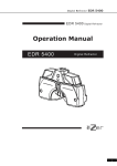
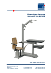
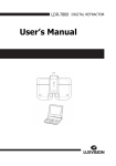
INTRODUCTION
Thank you for purchasing the Omni PINNACLE.
The Omni PINNACLE is a state-of-the-art system that provides the ultimate Ophthalmic and
Optometric instrument delivery. The unit is intended to deliver the instruments between the operator
and the patient in a fast and easy manner.
!
!
WARNING: The installation of Omni PINNACLE shall only be performed by a
qualified technician.
!
WARNING: All service (except replacing the two external fuses) and repairs
shall be performed by a qualified technician.
!
WARNING: All replacement parts or optional equipment shall be genuine Topcon
parts. Contact Topcon or your dealer for those items.
WARNING: The Omni PINNACLE is designed for use with TOPCON equipment.
If any other equipment is used, it shall meet the same certifications.
Please carefully read this manual to get the best system performance, and place the manual in a
convenient location for future reference.
PRECAUTIONS
1. Installation. Never position the unit where it will be exposed to moisture, direct sunlight, dust,
salty air, chemical storage areas, excessive temperature or humidity. Install the unit in a stable
place, free of uneven floors, vibration and shock.
2. Prior to Operation. Always check that all the cords are properly connected.
3. Operation. Take the proper steps to stop the unit (leaving the patient in a safe condition) if
anything is found wrong with the unit.
4. After Operation. Never hold and pull the connecting cord for disconnecting plugs. Excessive
force may be applied and cause damage to the inside connections. If the unit has not been used
for a long period of time, check the operation and safety features before using it again.
SAFETY CONCERNS
The Omni PINNACLE conforms to UL 2601-1, and CSA C22.2 No. 601.1-M90. Any of the defined
optional equipment can be added to the Omni PINNACLE without any additional safety hazards
being introduced and there is no disposal of any waste products associated with Omni PINNACLE.
2017000128 Revison: B, 02 /04
i
CONTENTS
1.
NOMENCLATURE
1.1
Omni PINNACLE Main Components
1
1
2.
PERFORMANCE AND SPECIFICATIONS
2
3.
ASSEMBLY
3.1
Tools
3.2
Omni System
3.3
Attaching Instruments
3.4
Roomlight Kit
3.5
Fluorescent Roomlight Kit (optional)
3.6
Fixation Targets (optional)
3.7
Computerized Linked System (optional)
3.8
Power Up
4
4
4
8
10
10
10
11
12
4.
SYSTEM OPERATION
4.1
Main Power Switch
4.2
Overhead Lamp Switches
4.3
Chair-Control Switch
4.4
Auto-Return Switch (for chair)
4.5
Auxiliary and Outlet Switches
4.6
Room-Light Control Switch
4.7
Screen Fixation Switches
4.8
Indirect Switch & Dimmer Control (optional)
4.9
Slit Lamp/Dual Fixed Arm Switches
4.10 System Reset Button
4.11 System Program Button
4.12 Sound
12
12
12
13
13
13
13
13
16
16
16
16
17
5.
ADJUSTMENTS
17
6.
MAINTENANCE
19
7.
TROUBLESHOOTING
20
8.
APPENDIX
Appendix A Roomlight Wiring Instructions
Appendix B Fluorescent Roomlight Wiring Instructions
22
22
23
ii
1.
NOMENCLATURE
1.1
Omni PINNACLE Main Components
Figure 1 shows the primary features and key components of the Omni PINNACLE.
Use the figure as a reference. Other components of the Omni PINNACLE are defined
in their own manuals.
Figure 1: Omni PINNACLE (Right Hand System shown)
2.
PERFORMANCE AND SPECIFICATIONS
Desk System
• Cabinet System Size:
• Mode of Operation:
• Type of Protection:
(Against Electrical Shock)
• Ingress of Water Protection:
• AP or APG:
28.0 in x 92.0 in x 31.0 in (711 mm x 2367 mm x 787 mm)
Continuous Use
Class 1 protection
Ordinary protection (IPX0)
Not AP or APG equipment
Counterbalanced Refractor Arm
• Adjustable Load Range:
8 to 20 lbs. (3.6 to 9.0 kg)
• Vertical Adjustment Range:
12 inch (305 mm)
Counterbalanced Slit Lamp Arm
• Adjustable Load Range:
22 to 55 lbs. (10 to 25 kg)
• Vertical Adjustment Range:
11.5 inch (292 mm)
Dual Fixed Arm
• Adjustable Load Range:
• Vertical Adjustment Range:
Electrical
• Voltage, Current, Frequency:
US Versions:
Non-US Versions:
• Rechargeable Instrument Wells
Battery Voltage:
Charge Rate (I & V limited):
Weight
• Net weight
0 to 100 lbs. (0 to 45.4 kg)
Fixed
120 VAC (± 10%), 7 A, 60 Hz
240 VAC (± 10%), 3 A, 50 Hz
3.5 v
Initial: 150 mA @ 8.5v
Trickle: 15 mA @ 12v
410 lbs. (186 kg)
Environmental Operating Conditions
• Ambient Temperature Range:
50 to 104 Degrees F (10 to 40 Degrees C)
• Relative Humidity Range:
30 to 75%
• Atmospheric Pressure Range:
10.1 to 15.4 psi (700 to 1060 hPa)
Environmental Storage/Transportation Conditions
• Ambient Temperature Range:
-20 to 130 Degrees F (-23 to 54 Degrees C)
• Relative Humidity Range:
30 to 95%
• Atmospheric Pressure Range:
10.1 to 15.4 psi (700 to 1060 hPa)
• Acceptable Storage Time
(in operating environment):
5 years
(in extreme environment):
20 days
2
Symbols used on the Omni PINNACLE
Cabinet Mounted Symbols:
Protective Earth ground location
CAUTION: Electrical shock possibility
!
ATTENTION: Information provided in manual
Alternating Current Symbol
Shipping Box Mounted Symbols:
Temperature Range for Storage/Transportation
%
Humidity Range for Storage/Transportation
3
3.
ASSEMBLY
3.1
Tools
Use the following tools to assemble the Omni PINNACLE:
1.
#2 Phillips screwdriver.
2.
Hex wrench kit.
3.
Level (not provided).
3.2
Omni System
3.2.1 Unpack the Omni PINNACLE and allow the unit to come to room temperature.
The standard components of the Omni PINNACLE are as follows: delivery
cabinet, counter weights (3), desk cabinet, counterbalanced refractor arm,
counterbalanced slit lamp arm, pole, lamp, and accessory kit. Use Figure 1 to
identify the main components for all assembly steps. Options are supplied as
ordered and the available options are; dual fixed arm (instead of a
counterbalanced slit lamp arm), indirect hanger, indirect wall-mount kit,
overhead cabinet, sink cabinet, fixation targets, and fluorescent roomlight kit.
3.2.2 The delivery cabinet must be moved into position first. Lift the cabinet (1
person required) by grasping the indentations by the kick. Carefully move the
delivery cabinet into the desired position by lifting and sliding. Once in
position, remove the temporary lumber on the bottom side and discard.
!
WARNING: To prevent damage to the unit, do not lift the unit by the curved
fiberglass tops.
3.2.3 Remove the access door screw using a #2 Phillips screwdriver. Slide the pole
into the delivery cabinet with the holes facing the backside. Make sure the pole
fits completely into the two pole brackets in the delivery cabinet. Slide the pole
all the way down to engage the rotational lock. Once engaged the pole will not
rotate. Securely tighten the four (4) 3/8-16 inch set screws using a 3/16 Hex
wrench.
3.2.4 Lift (1 person required) the (3) three counter weight blocks into the delivery
cabinet through the access door.
WARNING: To prevent damage to the unit, carefully lift and tilt the blocks
through the access door. Do not scape laminate, cables , or
electronics.
3.2.5 Level the delivery cabinet in two directions by turning the four (4) cabinet
glides in each corner of the cabinet. Use the pole as a guide.
!
3.2.6 Remove the three drawers from the desk cabinet by disengaging the cabinet
slide lever on both sides.
3.2.7 Lift the desk cabinet (1 person required using cabinet handholds) and place
close to the delivery cabinet. Once in position, remove the temporary lumber
on the bottom side and discard.
4
3.2.8 Install the leg to the underside of the fiberglass top with screws. Securely
tighten the four (4) 1/4-20 inch screws and 1/4 inch lock washers using a 5/32
Hex wrench.
3.2.9 Flip the top and place the fiberglass top (sculptured end) next to the delivery
cabinet (see Figure 1 for the proper right-handed orientation, left handed
systems are the mirror image) and on top of the desk section. Tighten to the
desk section with screws into inserts. Securely tighten the four (4) 3/8-16 inch
screws and 3/8 inch flat washers using a 7/32 Hex wrench.
!
WARNING: To prevent damage to the unit, do not lift the unit by the curved
fiberglass tops.
3.2.10 Level the desk cabinet in two directions and adjust the height by turning the
four (4) cabinet glides in each corner of the cabinet and the one under the leg.
Use the desk surface as a guide.
3.2.11 Install the three drawers into the desk cabinet by aligning the cabinet slides on
both sides and pushing the drawers all the way into the cabinet.
3.2.12 Lift the slit lamp arm or optional dual fixed arm (1 person required) over the
pole, and slide it down the pole to the height desired. See Figure 3.2 for the
suggested optimum mounting location. Securely tighten the set screws using a
3/16 Hex wrench to hold the arm in place. Feed the cord from the arm down
through the pole (or the cabinet top hole) and plug into the slit lamp arm
connector on the electrical receptacle panel. If an optional dual fixed arm is
used, connect the second cable to the keratometer arm connector on the
electrical receptacle panel. See Figure 3.3 for the Omni PINNACLE connector
mounting location.
Pole
34
inch
6
inch
42
inch
Refractor Arm
Slit Lamp Arm
Back
side of
Omni
Dual Fixed Arm
(Optional)
Figure 3.2: Instrument arm mounting locations
5
Jumper at
TP4
Diagnostics
Port
Indirect Power
Cable
2031000125
Jumper at
TP9
Jumper at
TP7 and TP8
Beeper
Screen Cable
2031000116
Indirect Cable
2031000111
Remote IR
Sensor Cable
2031000701
Slow Speed Adjust
F2
Slit Lamp
Arm Power
Roomlight Cable
2031000122
F6
Keratometer
Arm Power
Fuse F2
5A 250V S.B. (all VAC)
Fuse F3 & F5
5A 250V S.B. (120V units)
3A 250V S.B. (240V units)
Fuse F4
2A 250V S.B. (120V units)
1A 250V S.B. (240V units)
Chair
Control
F5
F4
F3
Fuse F6
5A 250V Normal Blow (120V units)
3A 250V Normal Blow (240V units)
Figure 3.3: Omni PINNACLE Printed Circuit Board
6
3.2.13 Lift the refractor arm (1 person required) over the pole, and slide it down the
pole to the height desired. See Figure 3.2 for the suggested optimum mounting
location. Securely tighten the set screws using a 3/16 Hex wrench to hold the
refractor arm in place.
3.2.14 Optional. Attach the chart projector arm into position on the pole and secure in
place.
3.2.15 Unpack the overhead lamp and install the 65 W bulb (provided). Slide the lamp
cord down the pole, and plug the cord end into the outlet marked LAMP.
Connect the lamp to the lamp cord, then insert the lamp into the top of the pole.
Push the excess cable down into the pole, while doing so. Tighten the screws
securely using a 1/8 inch Hex wrench to secure the lamp in place.
!
WARNING: Do not use a higher wattage bulb.
3.2.16 Optional. Clamp the indirect (BIO) hanger onto the pole or mount to the wall
by using the optional wall mounting kit. Secure the indirect hanger clamp by
tightening the two screws with a 5/32 Hex wrench. Feed the indirect cable into
the Omni PINNACLE (down the pole if mounted on the pole or through the
large wire hole on the side). Mate the other end of the 2-pin power cable into
the top of the electronic board and the 8-pin LED cable onto the middle right
portion of the electronic board marked INDIRECT. See Figure 3.3 for the
Omni PINNACLE connector mounting location. Secure the cables in one of the
wire clamps provided. See section 3.3.4 for indirect voltage options.
3.2.17 Place the chair cable through the large wire hole in the delivery cabinet, route
the cable through the provided wire channel (under the access door), and mate
into the 9-pin connector marked CHAIR on the bottom left corner of the
electronics board. See Figure 3.3 for the Omni PINNACLE connector mounting
location. Plug the power cord of the chair into a grounded wall outlet. (NOTE:
Using a non-Topcon chair may require an adapter, see Table 1 for pin
functionality. The chair supplies AC power to the Omni PINNACLE, and the
Omni PINNACLE acts as a switch and returns the power to the chair to make it
go up and down.)
Pin
1
2
3
4
5
Function
Earth Ground (from chair)
AC Neutral (from chair)
AC Hot (from chair)
N/C
Down (solenoid engaged)
Pin
6
7
8
9
Function
N/C
Down Limit Switch (engaged)
Up (pump engaged)
Safety Switch Loop
Table 1: Chair Connector Pins and Functions
7
3.2.18 Unpack the remote control and place two (2) AAA batteries into it. Make sure
the batteries are installed in the proper direction. Place the remote control into
the recessed area in the delivery cabinet top.
3.2.19 Optional. Mount the overhead cabinet to the wall using the provided cleat
(some models) or directly through the back cabinet wall. Securely anchor the
cabinet to the using large screws into the wall structure (metal or wood stud).
Plug in task light.
3.2.20 Optional. Plug in the X-ray viewer into the power strip under the table, and
plug the power strip into either a wall outlet or the base electronics located in
the delivery cabinet.
3.2.21 Optional. Verify that the sink drain and supply have been installed. Move the
sink cabinet next the other sections of the cabinet. Adjust the level and height
of the cabinet to match the other components. Have the plumbing lines
connected and tested for leaks.
!
3.3
WARNING: All plumbing connections shall be made by a qualified plumber,
an shall be in accordance all federal, state, and local codes.
Attaching Instruments
The instruments that connect to the Omni PINNACLE must be mounted and
configured properly before operation. The Omni PINNACLE was designed for Topcon
instruments. Consequently, adjustments may be required for other brands of
instruments and/or tools.
!
WARNING: All instruments that are attached to the Omni PINNACLE shall
be UL 2601-1 and CSA C22.2 No. 601.1-M90 compatible.
3.3.1 Refractor
Mount the refractor onto the end of the refractor arm by removing the set screw
in the end of the shaft, sliding on the refractor, tightening the locking clamp,
and reinstalling the set screw through the refractor clamp into the shaft. This
keeps the refractor from sliding off of the arm. Level the instrument in the
exam position.
If a computerized vision tester is used, repeat the same process except feed the
cable through the wire channel in the top of the arm extrusion then into the top
hole in the Omni PINNACLE pole. Connect to the vision tester power supply,
which must be located in the delivery cabinet.
3.3.2 Slit Lamp
Mount the Slit Lamp onto the end of the S-arm or the optional dual fixed arm
by placing the pivot pin (on the bottom of the tabletop) into the arm bushing.
Lock the Slit Lamp on the arm by tightening the knob. Plug the cord from the
arm into the transformer box. The S-arm is factory preset for a 35-40 lb. Slit
lamp. Should a heavier slit lamp be used, the slit lamp arm may need to be re8
adjusted to accommodate the heavier instrument. See section 5.4 in this manual
for details. Level the instrument in the exam position.
If an optional dual fixed arm is used, mount the Slit Lamp, transformer and
chin rest to the outside location on the top.
3.3.3 Keratometer (optional)
A standard K-arm cannot be used with an S-arm on the Omni PINNACLE.
If an optional dual fixed arm is used, mount the Keratometer (all models
including automatic Keratometers/Refractors), transformer and chin rest to the
inside location on the top. The Topcon OMB-1 plug kit may be required to
connect the instrument power cord to the power cord supplied with the arm.
Level the instrument in the exam position.
3.3.4 Indirect (optional)
The indirect voltage is factory set at 6 volts, but is designed for an easy field
change to 5, 7.5, and 12 volts. To change the voltage, open the Omni
PINNACLE side door in the delivery cabinet and change the jumper(s) on the
circuit board to the configuration needed for the desired operating voltage. See
Table 2 for the jumper configurations and Figure 3.3 for their locations. Once
set, plug the indirect into the twist-lock connector on the bottom of the indirect
hanger. Hang the indirect headset onto the hook.
Indirect Jumper Status
TP7 in and TP8 in
TP7 in and TP8 out
TP7 out and TP8 in
TP7 out and TP8 out
Resulting
Voltage
5.0 volt
6.0 volt (factory set)
7.5 volt
12.0 volt
Table 2: Indirect (BIO) voltage settings
3.3.5 Rechargeable Instrument Handles
The instrument console is supplied with three recharging wells for use with
rechargeable instrument handles. Simply inserting them into the well charges
the instruments. Green indicator lights are provided at each well to indicate that
the instrument is in a charging condition. If the light is not lit, then the
instrument is not charging. The wells are wired at the factory at 3.5 volts DC.
3.3.6 Chart Projector (optional)
The chart projector may be mounted on the wall or on the Omni PINNACLE. If
mounted on the Omni PINNACLE, the chart projector arm supports any
automatic chart projector. The arm has a .75 inch diameter socket for mounting
a projector. The maximum extension of the arm with load, is 7 inches, and has
a capacity of 22 lbs. (10 kg). Plug the chart projector into the auxiliary outlets
(marked AUX 1 or AUX 2) on the Omni PINNACLE.
9
3.4
Roomlight Kit
The room light kit allows the Omni PINNACLE to be an independent control of the
room light environment. (NOTE: This is for incandescent lighting only). A qualified
WARNING: All electrical connections shall be made by a qualified electrician,
an shall be in accordance all federal, state, and local codes.
!
electrician shall wire the un-terminated end of the room light cable directly into the
electrical system of the room (in accordance with local codes). Refer to the enclosed
installation instructions in Appendix A.
Once wired, connect the room light cable to the Omni PINNACLE by plugging into the
2-pin connector located in the middle right portion of the electronic board marked
ROOMLIGHT. See Figure 3.3 for the Omni PINNACLE connector mounting location.
Secure the cables in one of the wire clamps provided. Programming is described in
Section 4: SYSTEM OPERATION.
3.5
Fluorescent Roomlight Kit (optional)
The fluorescent room light kit allows the Omni PINNACLE to control the power of
fluorescent room lights. A qualified electrician shall wire the single gang box of the
fluorescent room light cable directly into the fluorescent electrical system of the room
(in accordance with local codes). Refer to the enclosed installation instructions in
Appendix B.
!
WARNING: All electrical connections shall be made by a qualified electrician,
an shall be in accordance all federal, state, and local codes.
Once wired, connect the fluorescent room light cable to the Omni PINNACLE by
plugging into the internal outlets marked AUX 1 or AUX 2. Secure the cable in one of
the wire clamps provided. Programming is described in Section 4: SYSTEM
OPERATION.
3.6
Fixation Targets (optional)
The Omni PINNACLE can control fixation targets. Place the screen cable through the
large wire grommet in the delivery cabinet, route the through the wire channel under
the access door, and mate into the black connector marked SCREEN on the middle left
side of the electronics board. See Figure 3.3 for the Omni PINNACLE connector
mounting location. Mate the other side of the cable into the underside of the round,
fixation target tube. Mount the tube and fixation light as required. Adjust the position
of the round, fixation target tube for optimum viewing.
3.7
Computerized Linked System (optional)
The computerized vision tester power supply is placed inside the delivery cabinet.
Install the paper roll and top cover. Set the Dip switches to the proper positions based
on the configuration of the system. See the vision tester user manual for the
information. Plug the power cord into the outlets in the electrical assembly. Once set,
turn the power supply power switch ON and place it on its end (larger end down) in
the delivery cabinet with the connectors facing outward.
Mate the arm connector (routed previously into the delivery cabinet) to its mating
vision tester power supply connector labeled CV.
10
Place the One-Dial Controller on the end of the table surface located on the desk
cabinet. The instrument should be positioned facing the operator. Route the One-Dial
Controller cable through the wire grommet, through the pole to the delivery cabinet,
and then over to the power supply. Mate the connector to the vision tester power
supply connector marked KB. Secure the extra cable slack out of the way of the other
cables and moving parts.
Route the data cable from the Keratometer through the pole to the power supply. Mate
the data cable connector to the vision tester power supply connector marked COM1.
Place the Mirror Chart on the desk cabinet. The Mirror Chart faces the patient. Route
the small end of the power cord from the inside of the delivery cabinet, through the
connecting leg (chrome tube), through the hole plugs in the desk cabinet, and into the
instrument. Secure the cord under the desk cabinet by placing it into the gray wire
channel (provided). Plug the power cord into one of the two receptacles on the inside
of the delivery cabinet. Repeat the same routing for the data cable, and then mate the
connector to the vision tester power supply connector marked COM4.
Place the Computerized Lensmeter on the desk cabinet. The Computerized Lensmeter
should face the operator. Route the small end of the power cord from the inside of the
delivery cabinet, through the connecting leg (chrome tube), through the hole plugs in
the desk cabinet, and into the instrument. Secure the cord under the desk cabinet by
placing it into the gray wire channel (provided). Plug the power cord into one of the
two outlets on the inside of the delivery cabinet. Repeat the same routing for the data
cable, and then mate the connector to the vision tester power supply connector marked
COM2.
3.8
!
Power Up
WARNING: Check all power cords and electrical connections for damage prior to
powering up the system.
3.8.1 Plug in the power cord, and push the power button on the control panel. The
green light in the switch will light when powered. Check the functionality of
all the moving assemblies. Refer to the operation section of this document for
the details.
3.8.2 Turn ON all the components. Check the functionality of all the components.
Refer to the user manuals for each individual instrument for operation details.
Move the refractor arm and slit lamp to the exam position. Level the vision
tester and slit lamp table/arm.
3.8.3 Once satisfied with the connections of all the instruments, close the access door
of the Omni PINNACLE. Attach the access door with one (1) Phillip screw.
Tighten the screws securely. See the next section, SYSTEM OPERATION, for
details using the system.
11
4.
SYSTEM OPERATION
The Omni PINNACLE is intended to be a system to be configured to meet the needs of all
Ophthalmic and Optometric practices. The Omni PINNACLE is well suited for manual and
automated equipment, including fully computerized systems.
Each of the Omni PINNACLE control buttons performs specific operations, and those
operations and other significant functions are identified in the following paragraphs. Many of
the buttons are redundant, but are included to provide the ultimate in flexibility for the user.
Refer to Figures 4.1,4.2, 4.3 for the layout of the control buttons on the remote control,
control panel, and the slit-lamp or dual fixed arm, respectively.
4.1
Main Power Switch
This switch (O) supplies power to all instruments and is located on the remote control
and the control panel. Turn the power switch on before putting the instruments into
use. The instrument wells will remain powered all the time to maintain their charge as
well as the internal system power supply unless the main power cable is unplugged
(turns the Omni PINNACLE power off) from the wall. A green light on the control
panel will be lit indicating power is on.
4.2
Overhead Lamp Switches
The overhead lamp switches (ON, OFF) control the supply of electricity to the lamp
and control its brightness. They are located on the remote control and control panel
(except for an on/off toggle on the lamp head). The lamp can be turned on and off by
pressing these buttons, and they will manually override any presets.
To adjust the brightness, the remote control or control panel maybe used, but is only
displayed on the control panel. The remote control (only) requires that the mode
button (L for LAMP) must be pressed before any arrow button. Then press the large
UP arrow button on the remote or control panel and the lamp brightness will increase.
Press the DOWN arrow button on the remote or control panel and the lamp brightness
will decrease.
4.3
Chair-Control Switch
The ophthalmic chair height can be controlled from either the remote control, control
panel, or the slit lamp/dual fixed arm switch panel. Press the UP arrow button and the
chair will rise. Press the DOWN arrow button and the chair will lower.
4.4
Auto-Return Switch (for chair)
The remote control or the control panel can auto-return the chair. The auto-return
switch can be pressed directly on the control panel. The remote control (only) requires
that the mode button (C for CHAIR) must be pressed then the auto-return switch (A
for AUTORETURN) on the remote control will automatically return the chair to its
lowest position. Note-if the chair is a full power chair such as the OC-2300 or OC2400, the auto-return function will return the chair to its lowest and most upright
position.
4.5
Auxiliary and Outlet Switches
The auxiliary on/off switches (1 and/or 2 for Auxiliary #1 and #2) control power to the
auxiliary outlets on the electrical receptacle panel located inside the Omni PINNACLE.
12
One is primarily intended for the chart projector, and the other is for optional
equipment. When pressed ON the corresponding switch on the control panel will light.
4.6
Room-Light Control Switch
The Room-light control switches (ON, OFF, DIM) control the supply of electricity to
the incandescent room lights (with kit installed) and control its brightness. They are
located on the remote control and control panel. The room lights can be turned on and
off by pressing these buttons and they will manually override any presets.
To adjust the brightness, the remote control or control panel maybe used, but is only
displayed on the control panel. The remote control (only) requires that the mode
button (R for ROOM LIGHTS) must be pressed. Then press the UP button on the
remote or control panel and the room light brightness will increase. Press the DOWN
button on the remote or control panel and the room light brightness will decrease. A
preset dim condition can be set and then returned to by pressing the dim button.
4.7
Screen Fixation Switches (optional)
The screen on/off switches control the fixation targets on the screen on the remote or
control panel. The three available targets are (M) for muscle, (C) for child, and (F) for
fixation. FIXATION flashes a single red LED, MUSCLE flashes a white LED in the
target tube, and CHILD flashes white and red LEDs in series with an alerting sound in
the target tube.
13
Figure 4.1 Remote Control Buttons
14
Figure 4.2 Control Panel Buttons
Figure 4.3 Slit-Lamp or Dual Fixed Arm Buttons
15
4.8
Indirect Switch & Dimmer Control (optional)
Placing the indirect on its hook and removing it from its hook automatically turns the
indirect ophthalmoscope on and off. This switch is one of the activator buttons for
programming to a preset environment. The dimmer control varies the brightness
intensity of the indirect by pressing the up or down arrow button. Four lights help
show the intensity level. The intensity increases from – to +.
4.9
Slit Lamp/Dual Fixed Arm Switches
The slit lamp switch (marked INTRUMENT) turns the power to the slit lamp on and
off. This button is one of the activator buttons for programming to a preset
environment. The chair can also be moved up or down from this touchpad.
4.10
System Reset Button
The system-reset button is one of the activator buttons for programming to a preset
environment. It is intended to be the initial default setting for an examination room. In
other words, after manual adjustments have been made to the room environment,
pressing the system reset will return the room environment to the settings initially used
and preferred in the exam.
4.11
System Program Button
The system-programming button is located on the top front, right side of the control
panel. This button is used to program the overhead lamp, room lights, screen fixation
targets, and auxiliary outlets 1 and 2. The automatic functions are activated by any of
the three well units, the indirect hook, the slit lamp arm button, and/or system reset.
Follow the instructions to program any one of the Omni PINNACLE activators (wells,
indirect hook, slit lamp arm button, system reset).
4.11.1 Programming
1)
Place the activator (handheld or indirect) in or on its holder (i.e., the
hand held in the well cup or the indirect on the hanger) and turn on the
Omni PINNACLE main power. If the unit is not on or in its hanger
when the power is turned on, the system will not recognize the unit and
will do nothing.
2)
Press and hold the system program button until a beep sequence is
heard, then release. The button light will come ON.
3)
20 seconds are allotted to program each setting. A beep will be heard
each second during the 20-second window. A new 20-second window
will begin after each input.
4)
Using the Omni PINNACLE remote control or control panel, adjust the
environment to the desired settings.
5)
When the desired settings are obtained, remove the appropriate
handheld from its well cup or lift the indirect off of the hook or press
the slit lamp power button. A two-toned beep will be heard to indicate
that the setting has been recorded.
6)
Place the activator back in or on its holder and the environment will
change back to the settings before programming started.
16
7)
Programming is complete and will stay stored in memory until it is
changed.
4.11.2 Operation
1)
Once programmed, removing or lifting an instrument will return the
environment to the preset position.
4.12
5.
Sound
The Omni PINNACLE beeps help to distinguish that a function is working. If desired,
removing the TP9 jumper (by the black, round sound beeper on the circuit board) will
disable the sounds. See Figure 3.3.
ADJUSTMENTS
The refractor arm, slit lamp arm and/or optional dual fixed arm may require adjustment
depending upon the weight of the instrument in use. If problems arise, please refer to Section
7: TROUBLE SHOOTING.
5.1
Refractor Arm
5.1.1 Counterbalance Adjustment
To adjust the counterbalancing of the instrument arm, (refer to Figure 5)
remove the black plastic panel located at the instrument end of the arm by
unscrewing the two (2) round-head Hex screws, then lock the instrument arm
at its maximum elevated position.
Inside the arm you will see a castellated (slotted) nut. To adjust the refractor
arm, insert the end of a 5/32 Hex wrench into the castellated (slotted) part of
the nut. It can be turned to increase or decrease the counterbalance spring
tension. (NOTE: Follow the same method for adjusting the counterbalanced slit
lamp arm, but using a 3/16 Hex wrench instead.)
Turning the nut clockwise, as viewed from the instrument end of the arm,
increases the counterbalance force. Counterclockwise rotation loosens the
counterbalance force.
5.1.2 Brake Adjustment
At the instrument end of the arm, there is a handle operating the brake. This
handle locks the three arm functions simultaneously: the instrument end of the
arm, the pole end of the arm, and the counterbalance mechanism. Each of these
three brakes can be adjusted independently of the others.
At the instrument and pole ends of the arm are two (2) Hex set screws. The
small set screw adjusts the brake force. To adjust the brake, lock the handle
and turn the screw 1/4 turn. Clockwise rotation increases the braking force and
counterclockwise rotation decreases the braking force.
5.1.3 Counterbalance Brake Adjustment
In instances where the handle is not restraining vertical movement, the
counterbalance brake will need to be adjusted. The counterbalance brake
adjustment is located on the diagonal arm (refer to Figure 5). The arm will
17
have three (3) black screws with caps on one end and a small opening
underneath the middle black screw.
Lower or raise the arm slowly until the small Hex screw is aligned to the
opening. Once the Hex screw has been aligned, tighten the handle and turn the
screw clockwise approximately 1/4 turn. Please note, when activating the
handle, place your thumb between the handle and the inner wall when
tightening the small Hex screw. Fully activate the handle and press down on
the auxiliary arm. If the resistance is inadequate, repeat the above procedure
and turn the small Hex screw another 1/4 turn.
Figure 5: Counterbalanced Arm Adjustments
5.1.4 Drift Elimination
Occasionally, the arms tend to drift. Increasing the drag on the arm can
eliminate a slight drift. Drag is adjusted by turning the larger of the two (2) set
screws located at both ends of the arm. If drifting persists, use a level and
check that the stand pole is vertical. Only a small amount of vertical offset can
cause major drift problems.
5.2
Slit Lamp Arm
5.2.1 Counterbalance Adjustment
Adjustment is the same as Section 5.1.1.
18
5.2.2 Brake Adjustment
Adjustment is the same as Section 5.1.2.
5.2.3 Counterbalance Brake Adjustment
Adjustment is the same as Section 5.1.3.
5.2.4 Drift Elimination
Adjustment is the same as Section 5.1.4.
5.3
Dual Fixed Arm (Optional)
5.3.1 Brake Adjustment
The rotational brake is adjusted by tightening the external set screw on the side
of the arm at the pole end. Clockwise rotations will increase the locking
pressure and counterclockwise will decrease the locking pressure.
5.3.2 Drift Elimination
Occasionally, the arm may drift. Increasing the drag on the arm can eliminate a
slight drift. Drag is adjusted by turning the set screw located at the backside of
the arm at the pole end. Clockwise rotations will increase the drag. If drifting
persists, use a level and check that the pole is vertical. Only a small amount of
vertical offset can cause major drift problems.
5.4
6.
Instruments
The instruments may require periodic adjustments and calibrations. Refer to the
instrument manuals for those particular instruments for that information.
MAINTENANCE
!
WARNING: All service (except replacing the two external fuses) and repairs
shall be performed by a qualified technician.
There are no periodic maintenance requirements for the Omni PINNACLE. However, periodic
checks of all the functions, safety switches, and power cords should be performed every six
months. For operational detail, please refer to Section 4: SYSTEM OPERATION. If problems
arise, please refer to Section 7: TROUBLE SHOOTING.
It is recommended that the exterior surfaces of the Omni PINNACLE be cleaned with a mild
soap, water, and clean damp cloth to maintain a like-new appearance. Cleaning shall be
performed at least every six months.
19
7.
TROUBLE SHOOTING
!
WARNING: All service (except replacing the two external fuses) and repairs
shall be performed by a qualified technician.
If the Omni PINNACLE does not function properly, check the following points before asking
for assistance. Disconnect the main plug before any servicing is performed.
1)
Read this User Manual to verify the Omni PINNACLE functions. Full part descriptions
and diagnostic information is provided in the Service Manual (only dealers have
copies).
2)
Check to see that all cords and/or cables are securely connected, and that the power
light comes on when the power button is pressed.
3)
Replace any blown fuses. See below.
a)
First turn the power switch off and remove the power cable plug from the wall
outlet.
b)
Turn the center part of the fuse holder counterclockwise, and the holder comes
out.
c)
Replace the blown fuse with a new one (refer to Table 3). Push in and turn the
fuse holder to tighten.
Location
Base Chassis
Base Chassis
Fuse
Primary
Secondary
120 Volt
7A 250 v - SB
7A 250 v - SB
240 Volt
3A 250 v - SB
3A 250 v - SB
Table 3: Fuse Information
4)
Replace Lamp Bulb.
If the lamp does not light, check to assure that all switches are turned ON. If the lamp
still does not light, then replace the bulb with a bulb of bulb of 65 watts (or less.
!
!
WARNING: Do not use a higher wattage bulb.
WARNING: All replacement parts or optional equipment shall be genuine Topcon
parts. Contact Topcon or your dealer for those items.
5)
Check the diagnostic instruments at a wall outlet to verify proper function.
6)
If problems persist, contact your Topcon dealer or Topcon Medical Systems directly.
20
8.
Appendix
Appendix A Roomlight Wiring Instructions
A.1
General Notes and Precautions
•
Only a qualified electrician must perform installation of the room-light
interface kit to the incandescent lighting fixtures. The maximum dimming
power is 600W.
•
Power must be turned off before installing the kit.
•
The following diagrams are for 110/120 VAC or 220/240 VAC.
A.2
Installation Process
A.2.1 Turn off power. Remove fuses or turn circuit breaker off.
A.2.2 Mount a single gang handy box (not provided) in the wall 18 inch high directly
behind the Omni PINNACLE (or within 6 feet of the Omni PINNACLE).
A.2.3 Use the installation diagram, shown below, that matches the specific wiring
application. (Note: Serial application requires the wall switch to be turned ON
to allow the Omni PINNACLE control of the roomlights. Parallel application
requires the wall switch to be turned OFF to allow the Omni PINNACLE
control of the roomlights.)
A.2.4 Use the proper size wire nuts to make connections inside the single gang box.
A.2.5 Mount the electrical faceplate and connect the cable to the stand (see
installation instructions).
A.3
Installation Diagrams
Note: Stand or OMNI will be wired into hot feed like a standard wall switch.
Stand or OMNI
Hot to Stand or OMNI
Hot to
Lighting
Neutral to Lighting
Lighting
Figure A1:
Incandescent Roomlight Control
(Control of light from stand or OMNI only)
Note: Stand or OMNI will be wired into hot feed like a standard wall switch.
Stand or OMNI
Wall
Switch
Stand or OMNI
Hot to Stand or OMNI Wall Switch
Hot to Stand or OMNI
Neutral to Lighting
Neutral to Lighting
Lighting
a. Serial Installation
Figure A2:
Hot to
Lighting
Hot to
Lighting
Lighting
b. Parallel Installation
Incandescent Roomlight Control
(Control of light from stand or OMNI and/or wall switch)
21
Appendix B Fluorescent Roomlight Wiring Instructions
B.1
General Notes and Precautions
•
Only a qualified electrician must perform installation of the fluorescent
roomlight interface kit to the lighting fixtures.
•
Power must be turned off before installing the kit.
•
The fluorescent roomlight kit does not power the fluorescent roomlights, but
merely controls them as another switch.
•
This kit can NOT dim the fluorescent roomlights.
•
The following diagrams are for 110/120 VAC or 220/240 VAC and high
voltage (277V) ballasts. Use appropriate kit for the required application.
B.2
Installation Process
B.2.1 Turn off power. Remove fuses or turn circuit breaker off.
B.2.2 Mount the single gang handy box (provided) in the wall 18 inch high directly
behind the Omni PINNACLE (or within 10 feet of the Omni PINNACLE).
B.2.3 Use the installation diagram, shown below, that matches the specific wiring
application. (Note: Serial application requires the wall switch to be turned ON
to allow the Omni PINNACLE control of the fluorescent roomlights. Parallel
application requires the wall switch to be turned OFF to allow the Omni
PINNACLE control of the roomlights.)
B.2.4 Use the proper size wire nuts to make connections inside the single gang box.
B.2.5 Mount the electrical faceplate and connect the plug to the stand (see
installation instructions).
B.3
Installation Diagrams
Serial Installation
Hot (110V/120V or
220V/240V or
277VAC (Ballast))
Wall
Switch
Single Gang Box
Stand or Omni
NC
Hot to
Lighting
Neutral to
Lighting
Lighting
Relay
Notes:
1) Kit single gang box will be wired into hot feed like a standard wall switch.
2) If wall switch is not present, the stand or omni will control the lighting directly.
Parallel Installation
Wall
Switch
Hot (110V/120V or
220V/240V or
277VAC (Ballast))
Neutral to
Lighting
Lighting
Single Gang Box Stand or Omni
NO
Hot to
Lighting
Relay
Notes:
1) Kit single gang box will be wired into hot feed like a standard wall switch.
22
Topcon Medical Systems
37 West Century Road
Paramus, NJ 07652
800-223-1130
www.topcon.com
23